Advertisement
Advertisement
Table of Contents

Summary of Contents for Jansen GTS-1500E
- Page 1 Wood Shredder Chipper Owner’s Manual...
-
Page 2: Table Of Contents
Contents General 1. Limitations of use……......................4 2. Specification of use …………………………………………………………………………………4 3. Description of the machine…………………………………………………………………………4 4. Symbols……………………………………………………………………………………………..6 Working with the shredder 1. Safety and technical remarks………………………………………………………………………7 2. Before operating the machine ……………………………………………………………………10 3. Starting and operating the machine…………………………………………………………...…10 4. Transportation……………………………………………………………………………………..12 Maintenance and checks……………………………………………………………………………...12 Problems and solution…………………………………………………………………………………13 Assembly instruction………………………………………………………………………….……14-16... -
Page 3: Description Of The Machine
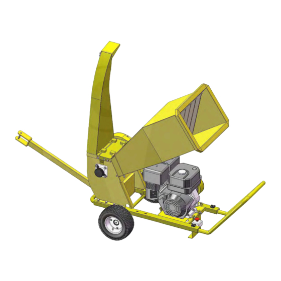
General 1. Intended use The shredder is designed solely for shredding/chipping all kind of newly cut tree branches of diameter up to 8.5 cm. 8.5cm 2. Restrictions You should not use the shredder for shredding/chipping metal, stones, plastics. if you are going to shred tree roots check that the diameter is less than 8.5 cm and remove all earth, sand stones. - Page 4 Fig.1 Output pipe Input pipe Protection rotor axe Engine Handlebar Emergency Stop Rotor...
-
Page 5: Symbols
4. Symbols N.B.: Before use, make sure that the manual has carefully read. Because familiar with the controls so as to use the machine correctly. Obey all safety instructions! -
Page 6: Working With The Shredder
Working with the shredder 1. Safety and technical remarks 1.1. The user should be 18 years old or more. 1.2. The machine should be positioned on a horizontal. Firm surface. 1.3. User must wear safety gloves (not provided with this unit), ear-protection and safety goggles. (fig.4) 1.4. -
Page 8: Before Operating The Machine
2. Before operating the machine Make sure the machine stands firmly on the ground and does not tilt in any way. The danger zone on the output of the machine must be respected, in order to avoid serious injury by chips thrown out of the output tube. -
Page 10: Maintenance And Checks
4. Transport Before moving the machine, stop the engine! Maintenance and checks All technical check-ups and maintenance should be done with the engine shut off and the spark plug cap removed from the spark plug. While cleaning the shredder, never spray the bearing with a high pressure washer! It could cause water to enter the bearings which will cause damage to the machine;... - Page 11 Problem & solutions Problem Cause Solution The shredder does not -the blades are worn too -change sharpen blades perform properly: the much counter-blade. Note that the blades are wood is not pulled in by -the diameter sharpened on both edges so they can be the machine itself.
- Page 12 UNPACKING When unpacking, check to make sure all the parts shown on the below diagram are included. 2 pcs...
- Page 13 MACHINE COMPONENT DEFINITION 1. Shredder Hopper 1 PC 2. Wheel 2 PCS 3. Inlet Hopper Assembly 1 PC 4. Outlet Hopper Assembly 1 PC 5. Tow Bar 1 PC 6. Handle Connecting Pipe 1 PC 7. Handle 1 PC...
-
Page 14: Assembly Instruction
ASSEMBLY INSTRUCTION Step 1: Attach and lock the wheel assembly(#30) and base(#22) using hex bolt M8x25(#53),lock washer Ø8(#54) and Flat Washer(#55). - Page 15 Step 2: 1.Secure the inlet hopper assembly(#4) to the roller cover plate assembly (#3) using hex bolt M8x20(#75),lock washer Ø8(#54), big flat washer(#40). 2. Secure the Outlet Hopper Assembly (#2) to the roller cover plate assembly (#3) using hex bolt M8x16(#39),lock washer Ø8(#54), big flat washer(#40).
- Page 16 Step 3: 1.Lock hand grip (#21),base(#22), roller base assembly(#18) using hex bolt M10x65(#67),flat washer Ø10 (#49),lock washer Ø10(#42) and nylon lock nut (#50). 2. Lock hand grip (#28) and base (#22) using hand wheel (#26). 3. Secure the tow bar (#20) to the hand grip (#21), then secure hitch pin (#63) using R pin(#64), the other side secure hitch pin(#33) using R pin (#64).
-
Page 17: Technical Specifications
Technical specifications Engine: 4 stroke Maximum rpm: 3600 Fuel: lead free petrol Shredding system: 2 blades on rotor and 1 counter-blade on the chassis. Blades are sharpened on both edges so they can be reversed. Gap between blades and counter-blade : 0.5mm (half a millimeter) Transmission : twin V belts running in parallel... - Page 18 PARTS DRAWING...
- Page 19 PARTS LIST Drawing No. Ref# Description Frame CPR150-00003 Outlet Hopper Assembly CPR150-07000 CPR150-03000 Roller Cover plate Assembly CPR150-08000 Inlet Hopper Assembly CPR150-00008 Mound Layer CPR150-00014 Inlet Hopper Rubber CPR150-00006 Blade CPR150-01000 Roller Assembly CPR150-00007 Spacer CPR150-00016 End Cap CPR150-00005 Striker Plate CPR150-00013 Belt Pulley Shroud SPA1782...
- Page 20 CPR150-00002 Hitch Pin N510-00019 Wing Nut M6 9101-06016-DX8.8 Hex Bolt M6x16 9301-06000-DX Flat Washer Ø6 9206-06000-DX Nylon Lock Bolt M6 9302-06000-DX Large Flat Washer Ø6 PARTS LIST Drawing No. Ref# Description 9101-08016-DX8.8 Hex Bolt M8x16 9302-08000-DX Big Flat Washer Ø8 9101-10016-DX8.8 Hex Bolt M10x16 9306-10000-DX...
- Page 21 9101-10020-DX8.8 Hex Bolt M10x20 9503-05010-DX Blind Rivet 9315-06000-DX Lock Washer 9110-06016-DX Screw M6x16 9101-08020-DX8.8 Hex Bolt M8x20 9101-08012-DX8.8 Hex Bolt M8x12...
Need help?
Do you have a question about the GTS-1500E and is the answer not in the manual?
Questions and answers