Table of Contents
Advertisement
Advertisement
Table of Contents

Summary of Contents for Black Tools GTS-1500-E
- Page 1 GTS-1500-E WOOD CHIPPER SHREDDER. OWNER’S MANUAL.
-
Page 2: Table Of Contents
CONTENTS. 1. GENERAL……………………………………………………………………3 Limitations of use…………………………………………………………3 Specification of use………………………………………………………3 Description of the machine…………………………………………..3 Symbols………………………………………………………………………..5 2. MACHINE COMPONENT DEFINITION………………………….6 3. UNPACKING……………………………………………………………...7 4. ASSEMBLY INSTRUCTIONS………………………………………….8 5. IMPORTANT INSTRUCTIONS FOR SETUP………………….12 6. WORKING WITH THE SHREDDER………………………………14 Safety and technical remarks……………………………………..14 Before operating the machine……………………………………15 Starting and operating the machine…………………………..15 Transportation……………………………………………………………16 7. -
Page 3: General
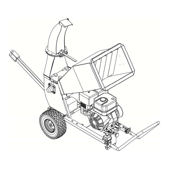
1. GENERAL Intended use The shredder is designed solely for shredding/chipping all kind of newly cut tree branches of diameter up to 8.5 cm. 8.5 cm Restrictions You should not use the shredder for shredding/chipping metal, stones, and plastics. If you are going to shred tree roots check that the diameter is less than 8.5 cm and remove all earth, sand stones. - Page 4 FIG.1 Output pipe Input pipe Engine Handle Protection Rotor axe Emergency Stop Rotor FIG.2A FIG.2B FIG.3...
-
Page 5: Symbols
SYMBOLS. N.B.: Before use, make sure that the manual has carefully read. Because familiar with the controls so as to use the machine correctly. Obey all safety instructions! -
Page 6: Machine Component Definition
2. MACHINE COMPONENT DEFINTION. Shredder Hopper Wheel 2PCS Inlet Hopper Assembly Outlet Hopper Assembly Tow Bar Wheel Axle Handle 2PCS Connecting Shaft... -
Page 7: Unpacking
3. UNPACKING. When unpacking, check to make sure all the parts shown on the below diagram are included. -
Page 8: Assembly Instructions
4. ASSEMBLY INSTRUCTION. Step 1: Put wheel (#30), flat washer Ø20 (#31), wheel bushing (#32) and wheel axle (#29) to the base (#22) using hex bolt M8x25(#53),lock washer Ø8(#54) and tire gasket(#21). Tighten the wheel axle (#29) using hex bolt M6x16 (#35) and hex nut M6 (#84). - Page 9 STEP 2: 1.Secure the inlet hopper assembly (#4) to the roller cover plate assembly (#3) using hex bolt M8x20 (#75), lock washer Ø8 (#54), big flat washer Ø8 (#40). 2. Secure the Outlet Hopper Assembly (#2) to the roller cover plate assembly (#3) using hex bolt M8x16(#39),lock washer Ø8(#54), big flat washer Ø8(#40).
- Page 10 STEP 3. 1. Attach the connecting shaft (#86) to the base (#22) using hex bolt M10x50 (#87), flat washer Ø10 (#49) and nylon lock nut M10 (50). Lock handle (#28) and base (#22) using hex bolt M10x45 (#85), flat washer Ø10 (#49) and nylon lock nut M10 (50).
- Page 11 STEP 4. 1. Please pull out the lock pin (#26) and turn up handle (#28), then insert the lock pin (#26) to the rear hole again when it’s working.
-
Page 12: Important Instructions For Setup
IMPORTANT INSTRUCTIONS FOR SET UP. Important instructions for setting up the device! You must read these before use! Adjust the distance between the blade and axel blade. The correct distance is approx. 2 mm +/- 0.5 mm. Check if the distance between the blade and the axel blade is consistent for both rotor blades by turning them manually. - Page 13 Under 1.5 kg of pressure, the belts can sag approx. 10 STRAIGHT 4. Check and tighten the screws of both driving belt pulleys. 5. Connect the batteries: The red positive cable coming from the battery should be connected to the magnet switch of the starter Connect the red positive cable here!
- Page 14 5. Fill up the lead free super petrol (95 octane) and engine oil (multigrade oil 10W40 or 15W40). Always fill the engine oil up to the maximum mark on the dipstick. 6. When starting the engine, please ensure that the emergency off switch is not pushed in, otherwise the engine will not start.
-
Page 15: Working With The Shredder
WORKING WITH THE SHREDDER. 1. Safety and technical remarks 1.1. The user should be 18 years old or more. 1.2. The machine should be positioned on a horizontal. Firm surface. 1.3. User must wear safety gloves (not provided with this unit), ear- Protection and safety goggles. - Page 16 1.8. Changing the blades of the rotor or the counter blade and checking blade bolts should only be done when the engine and rotor are stopped, the spark plug cap is removed and the rotor is blocked. 1.9. After one hour of use always check that all bolts and nuts are still tightened properly.
-
Page 17: Before Operating The Machine
2. Before operating the machine Make sure the machine stands firmly on the ground and does not tilt in any way. The danger zone on the output of the machine must be respected, in order to avoid serious injury by chips thrown out of the output tube. Chips can be thrown a distance of 12 meters, so onlooker must remain behind the direction of throw or at least 12 meters away from the output tube. - Page 18 WARNING! In case of emergency or any doubt, immediately activate the safety switch (red knob) to be found by the engine. (fig.11) Before starting the engine check that the bolts holding the input and output tubes are fully tightened. (fig.12, 13) FIG.10 FIG.9 FIG.11...
-
Page 19: Maintanence And Checks
MAINTANENCE AND CHECKS. All technical check-ups and maintenance should be done with the engine shut off and the spark plug cap removed from the spark plug. While cleaning the shredder, never spray the bearing with a high pressure washer! It could cause water to enter the bearings which will cause damage to the machine;... -
Page 20: Problems And Solution
PROBLEMS AND SOLUTIONS. Problem Cause Solution The shredder does not -the blades are worn too much -change or sharpen the blades and counter-blade. perform properly: the wood Note that the blades are sharpened on both edges so -the diameter is not pulled in by the they can be reversed. -
Page 21: Techincal Specifications
TECHNICAL SPECIFICATIONS. Engine: 4 stroke Maximum rpm: 3600 Fuel: lead free petrol Shredding system: 2 blades on rotor and 1 counter-blade on the chassis. Blades Sharpened on both edges so they can be reversed. Gap between blades and Counter-blade: 0.5mm (half a millimetre) Transmission: twin V belts running in parallel Dimensions: Max. -
Page 22: Parts Drawing
PARTS DRAWING. -
Page 23: Parts List
PARTS LIST. Ref# Drawing No. Description CPR150-00003 Frame CPR150B-01000 Outlet Hopper Assembly (Nether) CPR150-03000 Roller Cover plate Assembly CPR150-08000 Inlet Hopper Assembly CPR150-00008 Mound Layer CPR150-00014 Inlet Hopper Rubber CPR150-00006 Blade CPR150-01000 Roller Assembly CPR150-00007-DX Spacer CPR150-00016 End Cap CPR150-00005 Striker Plate CPR150-00013 Belt Pulley Shroud... - Page 24 N510-00019 Wing Nut M6 9101-06016-DX8.8 Hex Bolt M6x16 9301-06000-DX Flat Washer Ø6 9206-06000-DX Nylon Lock Bolt M6 9302-06000-DX Big Flat Washer Ø6 PARTS LIST. Ref# Drawing No. Description 9101-08016-DX8.8 Hex Bolt M8x16 9302-08000-DX Big Flat Washer Ø8 9101-10016-DX8.8 Hex Bolt M10x16 9306-10000-DX Lock Washer Ø10 9101-06020-DX8.8...
- Page 25 CPR150-14000 Engine Protector Assembly 9101-10060-DX8.8 Hex Bolt M10x60 9107-04016-DX Screw M4X16 9301-04000-DX Flat Washer Ø4 9206-04000-DX Nylon Lock Nut M4 9101-10020-DX8.8 Hex Bolt M10x20 9503-05010-DX Blind Rivet 9315-06000-DX Lock Washer 9110-06016-DX Screw M6x16 9101-08020-DX8.8 Hex Bolt M8x20 9101-08012-DX8.8 Hex Bolt M8x12 PARTS LIST Ref# Drawing No.
- Page 26 SUPPLIED BY BLACKTOOLS UNIT 10, HEDGEND INDUSTRIAL ESTATE, CT7ONB BIRCHINGTON. FOR SPARE PARTS AND SERVICES PLEASE CALL 01795500077.
Need help?
Do you have a question about the GTS-1500-E and is the answer not in the manual?
Questions and answers