Advertisement
Quick Links
19-5507; Rev 0; 9/10
General Description
The
MAX11835
evaluation
demonstrates a complete solution to drive single and
multilayer piezo actuators to create haptic feedback
for products featuring touch interfaces. The MAX11835
efficiently generates any type of user-programmable
waveforms including sine, trapezoidal, square, and
pulse to drive the piezo loads to create custom haptic
sensation. The low-power device directly interfaces
with an application processor/host controller through an
2
I
C interface and integrates various blocks including a
boost regulator, pattern storage memory, and waveform
generator in one package, thus providing a complete
haptic feedback controller solution.
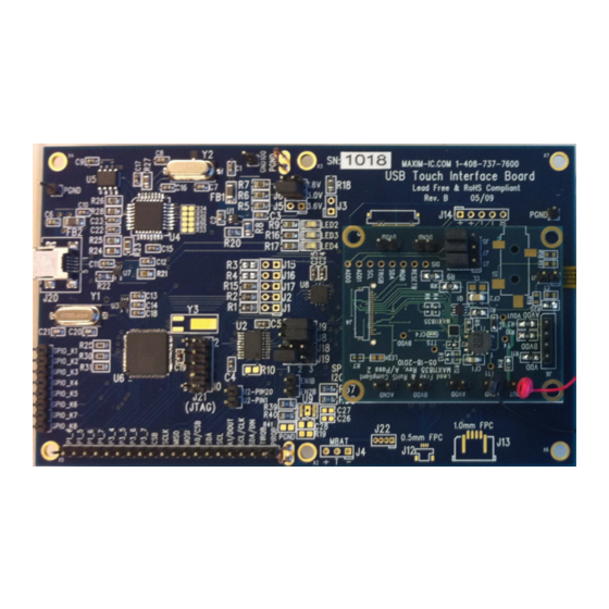
The EV system is a multiboard system that includes a
MAXQ2000 USB touch interface board (UTIB) and a
MAX11835 daughter board.
Note: The CD-ROM included with the EV kit contains
a User's Guide that provides information about the
graphical user interface (GUI).
Note: The MAX11835 is not a touch-screen control-
MAX11835 is not a touch-screen control-
ler and the touch panel is only provided for haptic
feedback purposes, with the 4-wire flex connector left
unconnected.
QTY
1
CD-ROM containing a USB driver, quick guide, GUI software for Windows XP
1
USB touch interface board (MAXQ2000 UTIB board)
1
Haptic actuator controller daughter board (MAX11835) with a connector to plug in to the UTIB board
Piezo driver MAX11835 daughter board with a connector to plug in to the UTIB2 board (included with the haptic
1
versions only)
Fujitsu 3.5in touch panel (Fujitsu 817-T010-1401-T670) with piezos mounted under them for haptic feedback
1
purpose only
2
CUI piezos (Cui Inc. CFT-44TW100-0.6A1-70C) for haptic feedback
1
Mini USB cable
Windows and Windows XP are registered trademarks of
Microsoft Corp.
_______________________________________________________________ Maxim Integrated Products 1
For pricing, delivery, and ordering information, please contact Maxim Direct at 1-888-629-4642,
or visit Maxim's website at www.maxim-ic.com.
MAX11835 Evaluation System
system
(EV
system)
DESCRIPTION
Convenient USB Interface
S
Touch Panel with Piezo Actuator Mounted for
S
Haptic Feedback
Analog Tracking-Mode Capability
S
Easy-to-Use Windows
M
S
(GUI) Allows Register Programming for Various
Haptic Waveforms
All Components Mounted on a Plexiglass Base for
S
Ease of Handling
Single-Supply Operation through the USB
S
Option for External Power Supply for the Boost
S
Regulator
Separate User's Guide Available for the Graphical
S
User Interface
Ordering Information
PART
TYPE
EV
MAX11835TEVS+
System
+Denotes lead(Pb)-free and RoHS compliant.
EV System Contents List
, and PCB schematic and layout files
M
Features
Graphical User Interface
PC
INTERFACE
INTERFACE
TYPE
USB
Windows
Advertisement

Related Manuals for Maxim MAX11835

Summary of Contents for Maxim MAX11835
- Page 1 USB touch interface board (MAXQ2000 UTIB board) Haptic actuator controller daughter board (MAX11835) with a connector to plug in to the UTIB board Piezo driver MAX11835 daughter board with a connector to plug in to the UTIB2 board (included with the haptic versions only) Fujitsu 3.5in touch panel (Fujitsu 817-T010-1401-T670) with piezos mounted under them for haptic feedback...
-
Page 2: Component Lists
MAX11835 Evaluation System Figure 1. MAX11835 EV System Component Lists MAXQ2000 UTIB Board DESIGNATION DESCRIPTION DESIGNATION DESCRIPTION 1FF -20/+80%, 16V ceramic 10FF Q20%, 10V ceramic capac- C1, C2, C11, capacitors (0603) itor (0805) Murata GRM188F51C105ZA01D Murata GRM219R61A106KE44D 10FF Q20%, 6.3V ceramic... - Page 3 MAX11835 Evaluation System Component Lists (continued) DESIGNATION DESCRIPTION DESIGNATION DESCRIPTION 196kI Q5% resistor (0805) Adjustable LDO linear Vishay CRCW0805196KJNEA U1, U7 regulators (5 SC70) Maxim MAX8512EXK-T 590kI Q5% resistor (0805) Vishay CRCW0805590KJNEA Octal-level translator (20 TSSOP) 61.9kI Q1% resistor (0805)
- Page 4 MAX11835 Evaluation System Component Lists (continued) DESIGNATION DESCRIPTION DESIGNATION DESCRIPTION Not installed, SMD ceramic R3, R8, R9, R11, 0I SMD resistors (0805) capacitor (0805) Not installed, capacitor R4, R6 4.7kI SMD resistors (0402) 200V diode 20I SMD resistor (0603) 2-pin headers, 0.1in pitch...
- Page 5 MAX11835 Evaluation System Table 3. Jumper Settings for the MAX11835 Daughter Board SHUNT JUMPER STATUS DESCRIPTION POSITION — Open Pin 2: AIN to MAX11835 Pins 2-3: Default to playback from the device memory Closed Pins 1-2: Analog tracking mode Closed ADD0 slave address pin (pin 1, DVDD;...
- Page 6 MAX11835 Evaluation System Figure 2a. UTIB Schematic—Main (Sheet 1 of 2) ______________________________________________________________________________________...
- Page 7 MAX11835 Evaluation System Figure 2b. UTIB Schematic—Mini USB (Sheet 2 of 2) _______________________________________________________________________________________...
- Page 8 MAX11835 Evaluation System Figure 3. MAX11835 Daughter Board Schematic ______________________________________________________________________________________...
- Page 9 MAX11835 Evaluation System 1.0” Figure 4. UTIB PCB Layout—Silkscreen 1.0” Figure 5. UTIB PCB Layout—Top Assembly _______________________________________________________________________________________...
- Page 10 MAX11835 Evaluation System 1.0” Figure 6. UTIB PCB Layout—Top Layer 1.0” Figure 7. UTIB PCB Layout—Layer 2 _____________________________________________________________________________________...
- Page 11 MAX11835 Evaluation System 1.0” Figure 8. UTIB PCB Layout—Layer 3 1.0” Figure 9. UTIB PCB Layout—Bottom Layer ______________________________________________________________________________________...
- Page 12 MAX11835 Evaluation System 1.0” Figure 10. UTIB PCB Layout—Bottom Assembly 2000mil 1600mil 1.0” Figure 11. MAX11835 PCB Layout—Silkscreen _____________________________________________________________________________________...
- Page 13 MAX11835 Evaluation System 2000mil 1600mil 1.0” Figure 12. MAX11835 PCB Layout—Top Assembly 2000mil 1600mil 1.0” Figure 13. MAX11835 PCB Layout—Top Layer ______________________________________________________________________________________...
- Page 14 MAX11835 Evaluation System 2000mil 1600mil 1.0” Figure 14. MAX11835 PCB Layout—Layer 2 2000mil 1600mil 1.0” Figure 15. MAX11835 PCB Layout—Layer 3 _____________________________________________________________________________________...
- Page 15 MAX11835 Evaluation System 2000mil 1600mil 1.0” Figure 16. MAX11835 PCB Layout—Bottom Layer 2000mil 1600mil 1.0” Figure 17. MAX11851 PCB Layout—Bottom Assembly ______________________________________________________________________________________...
-
Page 16: Revision History
— Maxim cannot assume responsibility for use of any circuitry other than circuitry entirely embodied in a Maxim product. No circuit patent licenses are implied. Maxim reserves the right to change the circuitry and specifications without notice at any time. - Page 17 Mouser Electronics Authorized Distributor Click to View Pricing, Inventory, Delivery & Lifecycle Information: Maxim Integrated MAX11835TEVS+...
Need help?
Do you have a question about the MAX11835 and is the answer not in the manual?
Questions and answers