
Related Manuals for PenMount TOUCHSCREEN 6000

Summary of Contents for PenMount TOUCHSCREEN 6000
- Page 1 6000 OUNT OUCHSCREEN ONTROL OARD NSTALLATION UIDE Revision 1.8 20/November/’12...
-
Page 2: Trademarks
Trademarks PenMount, Microsoft, Windows and other trademarks and product names used in this manual are the properties of their respective owners and are acknowledged. -
Page 3: Revision Table
Refinement of Installation Diagrams in section 2.2. 21/Oct/’09 Chapter 2 > 2.3 > 2.3.1. Install PenMount 6200D Control Board: The picture of PenMount 6200x Control Board Upside is updated. Chapter 2 > 2.3 > 2.3.2. Install A PenMount 6202B Control Board: The picture of PenMount 6202x Control Boards Upside are updated. - Page 4 The updated installation guide of PenMount Windows universal driver is on chapter Error! Reference source not found.. 20/Sep/’12 Change screenshots to Windows 8 Add descriptions on Setup.ini and Install.ini in 3.2.2 Content of PenMount Universal Driver in Chapter 3 and Chapter 4 is re-organized.
-
Page 5: Table Of Contents
Uninstall PenMount Windows Universal Driver ..............28 3.3. Install PenMount X Window Driver on Linux ................28 3.3.1. Install PenMount Linux X Window RS-232 Driver and USB Driver ........29 3.3.2. Calibration Utilities ........................29 3.4. Install PenMount Windows CE Driver ..................29 3.4.1. - Page 6 The Device Information ......................42 4.8. Draw Utility ..........................42 4.9. The Contact Information ......................44 Chapter 5. PenMount Gesture AP for Windows 2000/XP/VISTA/7/8 ........45 5.1. Invoke PenMount Gesture AP ....................45 5.2. Configure PenMount Gesture AP .................... 46 PenMount Gestures’...
-
Page 7: Chapter 1. Introduction
PenMount 6000 control board offers both RS-232 and USB interfaces except 6300, which only supports USB interface. PenMount Touchscreen Control Board is a circuit board that you install between a touchscreen and a host computer. The control board converts touch input into digital data, and the device driver converts the data into mouse events used by the operating systems. -
Page 8: Drivers & Utilities
4.2/5.0/6.0/7.0 1.4. After Sales Service PenMount 6000 control boards and software are modified and updated on a regular basis. For more latest updated information, downloads, and technical support, please refer to our website at: http://www.penmount.com/... -
Page 9: Chapter 2. Install Penmount 6000 Control Boards
The procedures that follow describe how to install and configure the hardware for each of the PenMount 6000 Control Boards. 2.1. Installation Requirements You need the following to install a touchscreen using a PenMount 6000 Touchscreen Control Board: 2.1.1. Computer... -
Page 10: Installation Diagrams
Chapter 2 Installing PenMount 6000 Control Boards 2.2. Installation Diagrams 2.2.1. The connection of 6200D Control Board (for both RS-232 & USB Interfaces) -
Page 11: The Connection Of 6202B Control Board (For Both Rs-232 & Usb Interfaces)
Installing PenMount 6000 Control Boards 2.2.2. The connection of 6202B Control Board (for both RS-232 & USB Interfaces) - Page 12 Chapter 2 Installing PenMount 6000 Control Boards...
-
Page 13: The Connection Of 6300A Control Board (For Usb Interface Only)
Installing PenMount 6000 Control Boards 2.2.3. The connection of 6300A Control Board (for USB Interface Only) -
Page 14: The Connection Of 6500A Control Board (For Both Rs-232 & Usb Interfaces)
Chapter 2 Installing PenMount 6000 Control Boards 2.2.4. The connection of 6500A Control Board (for both RS-232 & USB Interfaces) -
Page 15: Rs-232 & Usb Boards (6000 Series)
2.3. RS-232 & USB Boards (6000 Series) All PenMount 6000 control boards use both RS-232 serial interface and USB interface except 6300 which only supports USB connection. There are currently four models in the 6000 Series. The general procedure for board installation is similar, though hardware connection and configuration varies for each board. - Page 16 Chapter 2 Installing PenMount 6000 Control Boards The mechanical diagrams of PenMount 6200D Control Boards: PenMount 6200D5 Touchscreen Control Board Mechanical Diagram PenMount 6200D8 Touchscreen Control Board Mechanical Diagram...
-
Page 17: Install A Penmount 6202B Control Board
2.3.2. Install A PenMount 6202B Control Board PenMount 6202B control boards are touchscreen control boards that use both RS-232 and USB interfaces and supports 4-wire and 5-wire touchscreens. The size of the board is 70.0 x 20.0 mm and it was designed-in with two kinds of connector. - Page 18 Chapter 2 Installing PenMount 6000 Control Boards The mechanical diagrams of PenMount 6202B Control Boards PenMount 6202B CZ4 Control Board Mechanical Diagram PenMount 6202B CW4 Control Board Mechanical Diagram PenMount 6202B CW5 Control Board Mechanical Diagram...
-
Page 19: Install A Penmount 6300A Control Board
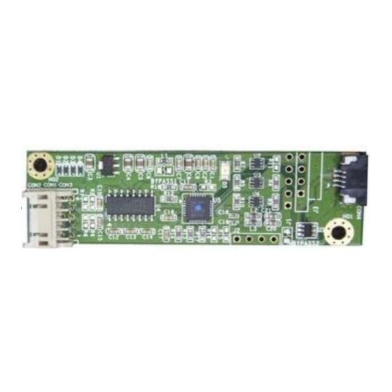
2.3.3. Install A PenMount 6300A Control Board The PenMount 6300A control board is a touchscreen control board that uses USB interface only. It supports 4-wire, 5-wire and 8-wire touchscreens. The size of the board is 26 x 60mm and it has two connectors and two dipswitches on-board. -
Page 20: Install A Penmount 6500A Control Board
2.3.4. Install A PenMount 6500A Control Board The PenMount 6500A control board is a touchscreen control board that uses both RS-232 and USB interfaces and supports 4-wire, 5-wire, and 8-wire touchscreens. The size of the board is 26 x 60 mm and it has two connectors and four dipswitches on-board. -
Page 21: Chapter 3. Install Drivers For 6000 Boards
Chapter 3. Install Drivers for 6000 Boards This chapter describes how to install drivers and other software that enables your PenMount 6000 control boards to work with various operating systems. PenMount 6000 boards support the following connections: 6200D 6202B 6300A 6500A ... -
Page 22: Penmount Dos Driver Functions
3.1.2. PenMount DOS Driver Functions PenMount DOS driver offers several functions. You can change the settings with the following utilities: PM2 Panel Run the batch file 'PM2.EXE'. Type the command at DOS prompt: Before running PM2, you must remove PenMount driver or another mouse driver, if you have installed one. - Page 23 Chapter 3 Installing Drivers for 6000 Boards Use <arrow key> (up/down) to select, and <Enter> to launch the following functions: (1) Draw (2) Calibrate (3) Detect (4) Configure (5) Packet (6) Help (7) Exit Draw Run the 'Draw' in PM2 Panel, and use the arrow keys or hot keys (A~Y) to choose one of 25 video modes.
- Page 24 After calibration, we recommend you to do drawing test to verify the touchscreen and monitor mapped properly. Function Keys: [Enter] - pass current point [F9] - camera, see above. Detect Detect PenMount automatically. You can press any key to interrupt the detection.
- Page 25 14, 15 COM4 (Base 03F8) (Baud 9600): IRQ 3, 4, 5, 6, 7, 8, 9, 10, 11, 12, 13, 14, 15 If you cannot find the PenMount, come 'configure' to set your COM port. Configure COM Port: COM5~COM9 is for setting customization.
- Page 26 Installing Drivers for 6000 Boards <counter> : counter of raw data : current dot <raw data> : the raw data of touch <coordinate>: the X, Y of A/D <offset> : the offset between last dot Function Key: [ESC] - exit Help See 'README.TXT' file Test...
-
Page 27: Install For Windows 2000/Xp/7/8 Systems
Reserved, please do not change the value Driver\Install.ini The options in the install.ini file affects the behavior of the PenMount device driver installer. The following table lists the supported options in install.ini, and the values in blue color are the default settings. -
Page 28: Device Driver Installation
ScanAllPorts The detection on some systems might take a few time to finish. Do not scan ports Serial Manually set up a PenMount non-PnP RS-232 on a specific COM port, operates in the baud <mode> rate specified. COMx For example, “COM1=6000,19200” means ,<baud>... - Page 29 Chapter 3 Installing Drivers for 6000 Boards If these is an older PenMount device driver installed on the system, a waning message box will appear when trying to install a new device driver. Please click the OK button and perform device driver uninstallation before proceeding.
- Page 30 “Mouse Device” or “Digitizer Device” on systems that supports Digitizer. A message box will show up. Please select “Yes” for installing PenMount as mouse mode; select “no” for digitizer mode. The later section describes more detail on these two modes.
-
Page 31: Penmount Device Types
Operating Modes Supported Not Supported 3.2.4.2. PenMount Monitor The PenMount Monitor is a utility designed for mouse modes. It will automatically be launched when system starts, and the PenMount Monitor icon will appear in the notification area. PenMount Monitor in Windows 2000/XP... -
Page 32: 3.2.4.3. Penmount Control Panel
Exit Exits the PenMount Monitor function. 3.2.4.3. PenMount Control Panel The PenMount Control Panel is the utility for configuring touch settings. Please refer to Chapter 4 for more detailed information on configuring PenMount. There are several difference between the mouse version and the digitizer version PenMount Control Panel. - Page 33 For digitizer devices, please check the “Tablet PC Settings” in the system Control Panel for mapping monitors. 3. A device configuration window will appear by clicking on the “PenMount 6000 USB” or “PenMount 6000 RS232” icon in the PenMount Control Panel. Only the mouse version has the “Setting” Tab.
-
Page 34: Refresh Device
Installing Drivers for 6000 Boards 3.2.5. Refresh Device If a PenMount device is not attached during device driver installation, user can still install by using the Refresh feature in the PenMount Control Panel. 3.2.6. Uninstall PenMount Windows Universal Driver 1. Go to Control Panel. Click “Add/Remove program”. Select ”PenMount Windows Universal Driver”, and click on the “Change/Remove”... -
Page 35: Install Penmount Linux X Window Rs-232 Driver And Usb Driver
3.4. Install PenMount Windows CE Driver Before installing PenMount WinCE Driver, you must have WinCE system installed and running in your device. You must also have had either PenMount USB control boards 6200D, 6202B, 6300A or 6500A installed. NOTE: Make sure you can move the WinCE cursor with a serial mouse attached to the target COM port (e.g. -
Page 36: Chapter 4. Driver Software Functions
Chapter 4. Driver Software Functions This chapter will guide you to the special software functions that configure and adjust the PenMount control boards and touchscreen hardware. Please note that not all of the functions are available for every driver. See the following table for drivers’ software functions and their availability for specific... -
Page 37: Standard Calibration
Driver Software Functions The first tab is the calibration tab, which consists of four features: “Standard Calibration”, “Advanced Calibration”, “Plot calibration data” and “Turn off EEPROM storage”. 4.1.1. Standard Calibration The Standard calibration function uses four points for calibration and one point for confirmation. -
Page 38: Advanced Calibration
PenMount’s application program as the result of user’s execution of Advance Calibration. 4.1.4. Turn off EEPROM storage This function disables the write-in of calibration data in the PenMount controller. This function is enabled by default. 4.1.5. Calibration in Command Line In some cases, users might want to launch calibration directly in command line. -
Page 39: Multiple Monitors
25= Advanced Calibration 25 4.2. Multiple Monitors PenMount supports two or more touchscreen displays for one system. Each monitor requires its own PenMount touchscreen control board, either installed inside the display or in a central unit. Multiple Monitors supports the following modes:... - Page 40 Chapter 4 Driver Software Functions If there is only one monitor attached, a warning message box will show Touch each screen as it displays “Please touch this monitor. Press ‘S’ to skip”, or wait for 10 second to skip automatically. Follow this sequence and touch each screen to map the touchscreens.
-
Page 41: Example: Mapping Two Touch Monitor In Windows Xp
Example: Mapping Two Touch Monitor in Windows XP Please make sure the touch monitor had plugged in and detected. In PenMount Control Panel, under Multiple Monitors tag, click “Map Touchscreens” then click “OK”. Please follow the message show the display to match the controller and touchscreen. - Page 42 Chapter 4 Driver Software Functions 3-2. When screen jump to Screen 2, please touch it. If screen 2 has no touch function, press “S” to skip it. Before proceeding to calibrate, you have to finish the procedure of “Map touchscreens”. 4-1.
-
Page 43: Multiple Devices
Multiple Devices Multiple Devices function is designed to let you use two or more monitors to display the same image. Software that supports this function includes the PenMount Windows Universal Driver (for 2000/XP/2003/VISTA/7/8) only. This driver for PenMount 6000 can support up to sixteen control boards. -
Page 44: Requirements
To use Multiple Devices with 6000 Control Boards, you need to do the following: To connect with RS-232 ports: Configure your computer hardware. See Chapter 2. Install PenMount 6000 Control Boards. Attach each 6000 board to a different computer’s serial port. -
Page 45: The Settings Tab
ATI and software such as Portrait Pivot Pro. For software operation and features, please refer to your software manual. PenMount supports rotation detection of 90, 180 and 270 degrees, and automatically adjust the touch position. On Windows XP 64 bit systems, however, users still need to manually turn on the rotation detection support with the instructions described below. -
Page 46: 4.5.1. Operation Mode
Select this mode and mouse only provides a click function when the touch is released. 4.5.2. Beep Sound All of PenMount’s drivers support the beep sound function; however, some PC systems may only offer a fixed buzzer sound. Beep Settings... -
Page 47: Edge Compensation
Driver Software Functions right button. For mouse devices, the PenMount supports two ways for simulating right mouse button. 1. Press and Hold as Right Click The press and hold delay and allowed area is adjustable in the “Settings” tab of the PenMount Control Panel. -
Page 48: The Device Information
The larger the value, the easier that the touch point reaches the edge of screen. 4.7. The Device Information The “About” Tab in the device configuration table shows information about the PenMount device, such as baud rate used, firmware version, and firmware configuration data. 4.8. - Page 49 Driver Software Functions Touch the screen with your finger or a stylus and the drawing screen registers touch activity such left, right, up, down, pen up, and pen down. Click Menu button for more functions. Show Pen Location is to show the locations where pen comes down and lifted up on the monitor.
-
Page 50: The Contact Information
Select Clear Screen to clear drawing. Select Exit to quit draw function 4.9. The Contact Information This option shows the exact version of the drivers and controller firmware. Updated drivers are available for downloading on the PenMount website at http://www.penmount.com/ . -
Page 51: Chapter 5. Penmount Gesture Ap For Windows 2000/Xp/Vista/7/8
3. To run PenMount Gesture AP. In the notification, right-click on the PenMount icon and select Gesture Enable from the menu. A PenMount Gesture AP icon will show up in the notification area. See the illustration below. PenMount Gesture AP is running. -
Page 52: Configure Penmount Gesture Ap
Configure PenMount Gesture AP To configure PenMount Gesture AP. 1. Right-click on the PenMount Gesture AP icon in the notification area, select Gesture Setting from the menu that appears. See the illustration below. Select Tools tab and click Gesture Setting button in PenMount Control Panel. - Page 53 Chapter 5 PenMount Gesture AP 3. 15 PenMount Gestures are provided in total. PenMount Gestures for Windows XP PenMount Gestures for Windows Vista / 7/ 8 4. In the [Gesture Setting] window, you can proceed to configure PenMount Gesture See picture below.
- Page 54 Action Configure Button. Configure to make use of PenMount Gesture AP’s built-in shortcuts. So that when a particular gesture is sensed, a specific action will be taken. PenMount Gesture AP have the following shortcuts built in: Note: For Disable touch function, after touch function is disabled, the mouse-pointer won’t move following your finger sliding on the touchscreen...
-
Page 55: Penmount Gestures' Default Values In Windows Xp
Chapter 5 PenMount Gesture AP 5.3. PenMount Gestures’ Default Values in Windows XP Page Up Page Down Backward Forward (Left Arrow) (Right Arrow) Copy Paste (Ctrl + C) (Ctrl + V) Undo Delete (Ctrl + Z) Zoom in Zoom out...
Need help?
Do you have a question about the TOUCHSCREEN 6000 and is the answer not in the manual?
Questions and answers