Advertisement
Advertisement

Summary of Contents for Tier 1 WS-165-150 Series
- Page 1 wner's anual S-165-150 eries ater oftener...
-
Page 2: Table Of Contents
WHAT'S INCLUDED OPERATING CONDITIONS ASSEMBLY INSTRUCTIONS FLUSHING THE WATER LINES MASTERPROGRAMMING PROGRAMMING KEYAND GENERAL INFORMATION... -
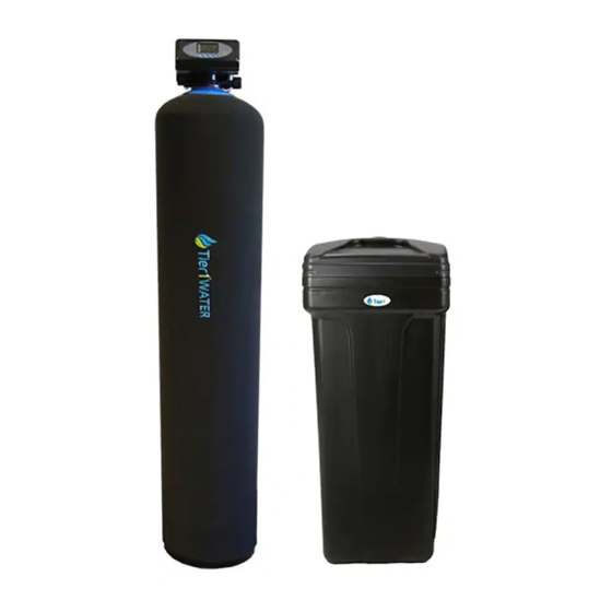
Page 3: What's Included
What is included with the WS-165-150 Check the entire unit for any shipping-related damage, missing parts, or damage to shipping cartons. Contact the transportation company for all damage and loss claims. Tier1 is not responsible for damages in transit. Small parts needed to assemble the Softener are contained in parts bags A and B, the control valve box, or in the owner'smanual zip-Lock bag. -
Page 4: Operating Conditions
Operating Conditions This softening system will operate at maximum efficiency when the following conditions are considered: Operating Conditions: Working pressure 21psi to 120psi Working Conditions Water temperature 40 °F - 120 °F (5°C - 50°C) Environment 40 °F - 120 °F (5°C - 50°C) temperature Working Environment Relative humidity... -
Page 5: Assembly Instructions
ASSEMBLY INSTRUCTIONS Locate the following parts: 1. Brine Tank – inside the brine tank you will find: A. Bypass Valve B. Control Valve C. Clear Drain Tubing (10') D. PVC Tubing E. Upper Distributor F. Brine Valve G. Brine Well H. - Page 6 PRIOR TO ASSEMBLY IMPROTANT NOTE: To avoid irreversible damage to connector threading, hand tighten plastic connections first. If leaks are noted during initial start up, gently tighten with tool. A. Prior to installation of this water softener, ensure you are aware of local laws and codes regarding the installation, use, and maintenance of water softeners.
- Page 7 ASSEMBLY INSTRUCTIONS STEP 1: Attach the Control Valve to the Resin Tank A. Locate the Master O-ring (from Parts Bag B) and lightly coat with silicone lubricant (from Owner’s Manual Zip-Lock Bag). Insert into bottom of control valve, as shown below. B.
- Page 8 ASSEMBLY INSTRUCTIONS E. Insert the connectors into the pipe fittings. The outlet connector containing water meter probe dock and the impeller must be installed in the outlet side of the bypass valve (as marked). F. Reinstall the plastic clamps on the connectors. Proceed to Step 4 Step 3: Assembly using the included bypass valve A.
- Page 9 ASSEMBLY INSTRUCTIONS D. To attach the bypass valve onto the control valve, remove plastic clamps from both inlet and outlet of bypass valve. Remove pipe fitting ends from bypass outlets and thread onto control valve. Connect bypass valve onto fittings and reinstall plastic clamps. E.
- Page 10 ASSEMBLY INSTRUCTIONS Figure 1.1 B. Attach brine well bracket (1) to brine tank by sliding bracket over brine well, as shown in Figure 1.1. C. Remove nut from threaded end of brine well bracket. D. Insert bracket into top hole of brine tank (2). Replace nut on bracket outside of hole in tank. E.
- Page 11 ASSEMBLY INSTRUCTIONS J. Insert the red brine line flow control (from Parts Bag B) with the cone side facing into control valve, into the control valve brine line connector. K. Insert brine line into control valve. Tighten the nut onto the brine line connection, as shown in the area of magnification below.
- Page 12 ASSEMBLY INSTRUCTIONS C. Secure the clear drain tubing over a floor drain or other suitable drain. Check your local codes to ensure compliance. STEP 6: Connect the backwash hose to the control valve A. Insert washer (from Parts bag B) into ribbed drain connector. B.
-
Page 13: Flushing The Waterlines
FLUSHING THE WATERLINES Before operating water softener for the first time, flush out your water lines and the water softener bypass. • Check that bypass is closed. Knob on top of inlet should be turned to "By-Pass" (side opposite of "In-Serv") •... -
Page 14: Masterprogramming
MASTER PROGRAMMING Valve Programming Instructions buttons simultaneously for 3 seconds to unlock. ∗ When LED is on press and hold both and the will turn on. This indicates you are in the programming mode. ∗ To program the valve, press ∗... - Page 15 FACTORY DEFAULT SETTINGS Function Indicator Factory Default Parameter Set Range Instruction Time of Day Random 00:00 23:59 Set the current time of day while the “:” flashes. ~ Meter Delayed. Regeneration occurs at the set regeneration time A-01 once the gallons used reaches zero (0). Control Mode A-01 A-01...
- Page 16 MASTER PROGRAMMING Step by Step Programming Instructions Items Process steps Screen Display Note: when “12:12” flashes; Time of Day needs to be reset. 1. Press to set Time of Day; both and will light and the “:” symbol will flash. 2.
- Page 17 • To verify that your water softener is functioning correctly, you can take a water sample test to verify hardness reduction. • Tier1 recommends the Water Total Hardness Test (3-pack) by Tier 1. Purchase the test at www.tier1filters.com/harness-test or by calling 1-855-378-9116.
- Page 18 CARE AND MAINTENANCE BRIDGING Humidity or the wrong type of salt may create a cavity between the water and the salt. This action, known as “bridging”, prevents the brine solution from being made, preventing the water softener from working. If you suspect salt bridging, carefully pound on the outside of the plastic brine tank, or pour some warm water over the salt to break up the bridge.
-
Page 19: Programming Keyand General Information
PROGRAMMING KEY AND GENERAL INFORMATION Programming Key Time of Day Indicator LED on, displays the time of day. LED flashes, need to reset time of day after electrical service has been interrupted for 3 days or more. Button Lock Indicator LED on, indicates the buttons are locked. - Page 20 S-165-150 eries ater oftener Tier1 ® www. ilters.com Tier1 ® is a registered trademark of US Water Filters, Inc. 1-855-378-9116 Zumbrota, Minnesota Copyright©2019 US Water Filters, Inc. All rights reserved. Version 18012019...
Need help?
Do you have a question about the WS-165-150 Series and is the answer not in the manual?
Questions and answers