
Summary of Contents for FORCE Unlimited DUO-FORCE
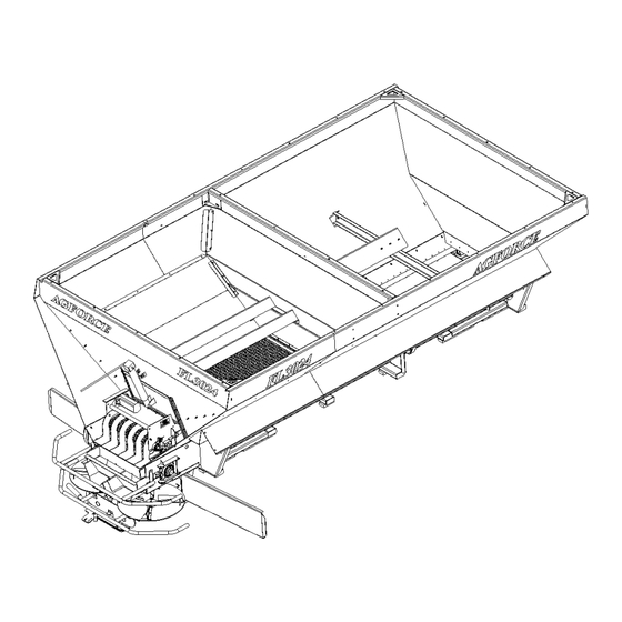
- Page 1 DUO-FORCE FOR AGFORCE FL3024 By FORCE Unlimited FORCE Unlimited 1504 S. Frederick Avenue Oelwein, IA 50662 (319) 283-4863 www.forceunltd.com...
- Page 2 LIMITED WARRANTY COMPANY NAME: _________________________________________________ COMPANY ADDRESS: ______________________________________________ CITY: _______________________________ STATE: _______ ZIP: ___________ MODEL: ________________________________________ SERIAL NUMBER: _______________________________ DATE PURCHASED: _____________________________ DEALER NAME: ________________________________ DATE WARRANTY CARD RETURNED: _____________ VIA: _____ WEBSITE _____ MAIL...
- Page 3 283-3086 the warranty registration card within 30 days from the date of delivery to original user. The installation of any Part that did not originate from FORCE Unlimited will void this limited warranty in its entirety. In the event of repair or replacement, the warranty period shall not be extended beyond the original warranty period.
- Page 4 LIMITED WARRANTY 2 YRS SHELL STRUCTURE, SPINNER FRAME (including inferior welds & cracking) CONVEYOR GEARBOX (including gears, bearings & seals) 1 YR SPINNER MOTORS & ADAPTERS (including bearings & seals) CONVEYOR MOTORS (including bearings & seals) VALVE MOTORS & CARTRIDGES CONVEYOR CHAIN –...
- Page 5 NOTE: THIS INSTRUCTIONAL MANUAL AND PARTS BOOK ONLY APPLIES TO DUO-FORCE UNITS S/N 11514 AND AFTER. IF YOUR UNIT USES RUBBER SEALING STRIPS INSTEAD OF STAINLESS STEEL, OR HAS A SERIAL NUMBER PRECEDING 11514, CALL FORCE UNLTD. TOLL FREE AT 1-800-632-5986 FOR DETAILS.
- Page 6 SPREADERS * GPS EQUIPMENT * CONVEYORS Table of contents item Page no. Instructional Manual Initial Setup & Maintenance Duo-Force Removal Duo-Force Installation Duo-Force Valve Block Visual Reference Parts Manual Hydraulic System DF-1.1 Conveyor Drive DF-2 Take-Up and Flow Reducer DF-3...
- Page 7 FORCE UNLTD. SPREADERS * GPS EQUIPMENT * CONVEYORS Duo-force Initial setup & maintenance Sprocket Locations BELT TRAVEL FRONT OF BOX NOTES: 1.) When flat wire belt is properly tightened, you should be able to lift the center of the belt 1” – 1 ½” off the conveyor bed.
- Page 8 5.) Remove Hillside Flow Divider by removing (2) bolts at rear of Duo-Force insert. (Fig. B) Hillside Flow Divider will then slide out. 6.) If necessary, loosen the four Take-Up Cover Sealer bolts to release tension Fig.
- Page 9 FORCE UNLTD. SPREADERS * GPS EQUIPMENT * CONVEYORS DUO-FORCE REMOVAL (Continued) Fig. D Removing Duo-Force insert with fork truck NOTE: Hinged Panels MUST be re-fastened to the Box Divider before reinstalling the Duo-Force conveyor insert Fig. E Removing Hinged Panel Bolts Inverted “V”...
- Page 10 Hillside Flow Divider and its brackets (Fig. A) DO NOT replace chain shield bolts that were common to the Hillside Flow Divider brackets 2.) Using a fork truck, insert Duo-Force conveyor insert (Fig. B) 3.) Slide conveyor insert in so that brackets align with second chain shield bolt holes.
- Page 11 FORCE UNLTD. SPREADERS * GPS EQUIPMENT * CONVEYORS DUO-FORCE INSTALLATION (continued) 5.) Hook the bent flange of the Hinge Panel under the 1.) Asd “fingers” on the back side of the Box Gusset panel (Fig. E) 2.) A 3.) Asdf 6.) Align front edges of Box Gusset and Hinged Panel, and...
- Page 12 FORCE UNLTD. SPREADERS * GPS EQUIPMENT * CONVEYORS ASDF DUO-FORCE INSTALLATION (continued) ASDF ASDF ASDF ASDF ASDF 8.) ASDF 9.) Install Upper & Lower Box Divider Panels and bolt together using ½” UNC x 1” carriage bolts, ½” flat washers, lock washers and ½” UNC hex nuts (3 of ea.)
- Page 13 FORCE UNLTD. SPREADERS * GPS EQUIPMENT * CONVEYORS DUO-FORCE INSTALLATION (continued) Asdf Asdf Asdf Asdf Asdf Asdf Asdf 10.) Asdf 11.) Asdf 12.) Asdf 13.) Install Take-Up Cover Sealer to Lower Box Divider panel using ¼” UNC x 1” bolts, ¼”...
- Page 14 UNC hex nuts (2 of ea.) 21.) Plug in electrical connector for rate sensor and for bin level sensor (if equipped) 22.) Disconnect Duo-Force hoses from Fig. N Hillside Flow Divider Installation each other and connect to fittings on Duo-Force conveyor motor HOME OF THE “FORCE”...
- Page 15 FORCE UNLTD. SPREADERS * GPS EQUIPMENT * CONVEYORS Agforce valve block configuration With duo-force Note: This page is for visual reference only. For details, see Parts Page DF-1.1 HOME OF THE “FORCE” FIELD Instructional Pg. 9...
- Page 16 SPREADERS*GPS EQUIPMENT*CONVEYORS agforce w/ duo-force,tri-force & quad force hydraulic setup w/ multibin valve block CONNECTIONS FOR UNITS W/ DUMP VALVE RETURN FLOW TO MAIN VALVE BLOCK (IN PLACE OF ITEM #10) POSITION OF RELIEF VALVE IN MAIN BLOCK...
- Page 17 FORCE UNLTD. SPREADERS * GPS EQUIPMENT * CONVEYORS DUO-FORCE HYDRAULIC SETUP PARTS KEY ITEM PART NO. DESCRIPTION QTY. 1211-00 Main Valve Block - Hydraulic 1202-119 Plug 1202-117 Adapter - Straight 1202-210 Adapter - Elbow 1211-80 Cartridge - PSI Compensator 1211-01A...
- Page 18 FORCE UNLTD. SPREADERS * GPS EQUIPMENT * CONVEYORS Duo-force hydraulic setup parts key (continued) ITEM PART NO. DESCRIPTION 1202-2056 Adapter- Elbow 1202-3015 Adapter- Tee 1202-102 Adapter- Straight 1202-202 Adapter- Elbow 2 w/o Dump Valve 3 w/ Dump Valve Hose Assembly (12’ Box) 1207-15 Hose Assembly (13’...
- Page 19 FORCE UNLTD. SPREADERS * GPS EQUIPMENT * CONVEYORS DUO-FORCE CONVEYOR DRIVE ITEM PART NO. DESCRIPTION QTY. 1217-99 Drive Sprocket Requires: Set Screw- 5/16” UNF x 5/16” Lg. Key Stock- ¼” Sq. x 1” 1217-30 Pillow Block Bearing Requires: Set Screw- 5/16” UNF, 5/32” Hex 2 ea.
- Page 20 1 ea. Lock Washer- 3/8” SS 1209-43 1 ea. Hex Nut- 3/8” UNC SS 1205-27 1 ea. As Req’d- 1233-1 Flat Wire Belt- Duo-Force & Duo-Force LTD Flat Wire Belt- Duo-Force XLG Specify Length 1233-2 Connecting Rod- Flat Wire Belt...
- Page 21 Nut- ¼” UNC SS 1205-11 1233-4 Idler Roller- Duo-Force & Duo-Force LTD 1233-39 Take-Up Bracket- Duo-Force & Duo-Force LTD 1233-35 Product 1 Flow Reducer- Duo-Force & Duo-Force LTD Requires: Hex Head Bolt- 3/8” UNC x 1” SS 1200-3011 Lock Washer- 3/8”...
- Page 22 1200-400SS Flat Washer- ½” SS 1209-61 Lock Washer- ½” SS 1209-63 Nut- ½” UNC SS 1205-36 1233-101 Lower Box Divider- Duo-Force & Duo-Force LTD 1233-201 Upper Divider Sealer Requires: Hex Head Bolt- ¼” UNC x 1” SS 1200-202 3 ea.
- Page 23 1209-22 4 ea. a feedgate slide Nut- ¼” UNC SS 1205-11 4ea. 1233-204A Take-Up Cover Sealer- Duo-Force & Duo-Force LTD Requires: Hex Head Bolt- ¼” UNC x 1” SS 1200-202 Lock Washer- ¼” SS 1209-22 Nut- ¼” UNC SS 1205-11...
- Page 24 SPREADERS * GPS EQUIPMENT * CONVEYORS Duo-Force Inverted “v” ITEM PART NO. DESCRIPTION QTY. Inverted “V”- Duo-Force & Duo-Force LTD 1233-72 Inverted “V”- Duo-Force XLG (18’ Box) 1233-72 XLG Requires: Note: Rear mount Hex Head Bolt- ¼” UNC x 1” SS...
- Page 25 Hex Head Bolt- 3/8” UNC x 1” SS 1200-203 Lock Washer- 3/8” SS 1209-43 Nut- ¼” UNC 1205-27 1236-1040 Hillside Flow Divider Extension- Duo-Force (Optional) Requires: Hex Head Bolt- ¼” UNC x 1” 1200-203 2 ea. Lock Washer- ¼” 1209-22 2 ea.
Need help?
Do you have a question about the DUO-FORCE and is the answer not in the manual?
Questions and answers