Advertisement
Quick Links
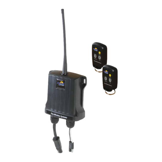
FLOE WIRELESS REMOTE
ASSEMBLY INSTRUCTIONS
KIT P/N 511-00832-00
INSTRUCTION P/N 611-00832-00
ISSUED: 3/22/17 REVISED 5/18
TOOLS REQUIRED
- 3/4" SOCKET
- 3/4" WRENCH
- 11/32" WRENCH
- PHILLIPS SCREW DRIVER
- TORQUE WRENCH
All material © 2018 FLOE International, Inc.
Unauthorized reproduction is strictly prohibited.
Specifications subject to change without notice.
Advertisement

Summary of Contents for Floe 511-00832-00
-
Page 1: Tools Required
- 3/4” SOCKET - 3/4” WRENCH - 11/32” WRENCH - PHILLIPS SCREW DRIVER - TORQUE WRENCH All material © 2018 FLOE International, Inc. INSTRUCTION P/N 611-00832-00 Unauthorized reproduction is strictly prohibited. ISSUED: 3/22/17 REVISED 5/18 Specifications subject to change without notice. - Page 2 WIRELESS REMOTE EXPLODED VIEW AND BOM KIT P/N 511-00832-00 PARTS LIST FOR 511-00832-00 ITEM PART NUMBER DESCRIPTION 001-70205-00 HHCS, 1/2-13 X 1" SS 001-70207-00 HHCS, 1/2-13 X 1 1/4" SS 001-71021-00 FLAT WASHER, 1/2" 18-8 SS 001-72525-00 RPHMS, 8-32 X 3/4" SS 001-76072-00 NUT, NYLOCK 1/2-13 ALUM.
- Page 3 STEP 1 - ASSEMBLE MAST MOUNT BRACKET 1/2" WASHER BRACKET START 1/2" NYLOCK NUTS ONTO BOLTS, DO NOT TIGHTEN UNTIL STEP #4 INSERT (2) 1/2 X 1 1/4" BOLT THROUGH SLIDE 1/2" ALUM. NUT INTO WASHER AND BRACKET. NUT TRACK ON BRACKET FIG.
- Page 4 STEP 3 #8/ NYLOCK NUT - ASSEMBLE RECIEVER ONTO MAST - INSTALL ANTENNA TO RECIEVER THREAD ANTENNA INTO TOP OF RECEIVER SCREWS THROUGH RECEIVER AND MAST FIG. 3 TOP SECTION OF MAST CONNECT WIRES TOGETHER STEP 4 - CUT DOUBLE SIDED VELCRO IN LENGTHS NEEDED TO SECURE THE WIRE TO THE FRAME OF THE LIFT IN A MANNER THAT WILL PREVENT THE WIRES FROM BEING HARMED FROM THE LIFT MOVING UP AND DOWN.
- Page 5 Floe Wireless Systems Reprogramming Receiver To Transmitter Fob Reprogramming a Remote Receiver to a Remote Transmitter Fob: Each transmitter has a unique identity. Each time a Remote Transmitter Fob is operated, it emits a secure RF signal. The Remote Receiver can learn new signals, thereby allowing the user to reprogram the Remote Receiver to match a new different Remote Transmitter Fob.
- Page 6 Do I need to Erase Current Settings? At the top of the Circuit Board are the ‘Learn Switch’, red ‘Power LED’ light (always on), and green ‘Learn LED’ light (on only during programming) . Before reprogramming a Remote Receiver, decide whether to erase the current settings or not. If replacing a lost Remote Transmitter Fob but still have another working fob, do not erase the current settings.
- Page 7 Reassemble the Remote Transmitter and Reinstall the Mast: SHEET 7 OF 7...
- Page 8 Alternate Reprogramming Receiver To Transmitter Fob For Alternate Reprogramming, place a magnet to the right side and upper corner of the receiver as shown. Hold any button on the remote until you hear the relay click. Confirm by pressing any of the buttons and listening for clicking of relay. A.
Need help?
Do you have a question about the 511-00832-00 and is the answer not in the manual?
Questions and answers