
Related Manuals for Meerstetter Engineering TEC-1092


Summary of Contents for Meerstetter Engineering TEC-1092
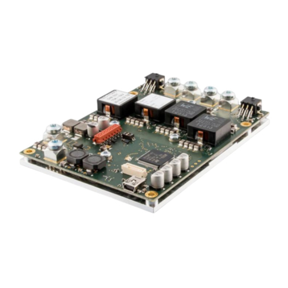
- Page 1 User Manual – TEC Controller TEC-Family: TEC-1092 TEC-1089 TEC-1122 TEC-1091 TEC-1090 TEC-1123 SWISS MADE...
-
Page 2: Table Of Contents
Index Introduction .......................4 Important Documents ..................4 How to Contact Support .................4 Basic Functions ......................5 The Status Bar of TEC Service Software ............5 Remote Control Options ................8 Operating the Power Stage ................9 Firmware Updates ..................11 Temperature Measurement ..................12 Object Temperature Measurement .............. 13 Heatsink Temperature Measurement ............ - Page 3 Email: contact@meerstetter.ch Meerstetter Engineering GmbH (ME) reserves the right to make changes without further notice to the product described herein. Information furnished by ME is believed to be accurate and reliable. However typical parameters can vary depending on the application and actual perfor- mance may vary over time.
-
Page 4: Introduction
Start the TeamViewer software from our website for a remote-control session. As soon as you start the tool we will recognize you, but please make sure to call or write us beforehand. TEC Family User Manual 5216A Meerstetter Engineering GmbH... -
Page 5: Basic Functions
Error: Error occurred. Output stage disabled Bootloader: Firmware is being updated ● Operating parameters for each channel Temperature with stability indication Current and voltage Figure 1. Status bar in the bottom row of the Service Software. TEC Family User Manual 5216A Meerstetter Engineering GmbH... - Page 6 If the TEC Controller enters the error condition, please go to the Monitor tab, there you can find the error number and description on the right side of the window. Alternatively, you can find a list of all errors here: 8.2 Error Numbers, Instances and Parameters TEC Family User Manual 5216A Meerstetter Engineering GmbH...
- Page 7 By default, temperature measurement calibration data is only imported when the se- rial number in the configuration file matches the connected device’s serial number. (This option can be disabled in the “Advance” tab at the bottom.) TEC Family User Manual 5216A Meerstetter Engineering GmbH...
-
Page 8: Remote Control Options
1-unit load receiver input impedance, allowing up to 32 transceivers on the bus. Not available on all TEC Controllers One option is the USB RS485 converter cable from FTDI Chip, available in different lengths. TEC Family User Manual 5216A Meerstetter Engineering GmbH... -
Page 9: Operating The Power Stage
5A limitation is reached. This means the output stage outputs 10V at 1A. In the other condition, a 1Ohm Resistor is connected. In this case the output stage reaches first the 5A limitation. This means the output stage outputs 5V at 5A. TEC Family User Manual 5216A Meerstetter Engineering GmbH... - Page 10 Both the static and live settings can be configured on the fly by remote control. The Service “TEC-Family MeCom Software does not permit to write live parameters. Refer to the document Communication Protocol 5136” for more information about bus controlled live RAM parame- ters. TEC Family User Manual 5216A Meerstetter Engineering GmbH...
-
Page 11: Firmware Updates
The TEC Controller will reboot once the update completes. ● You can check the firmware version in the tab “Monitor”. ● Re-import the before exported .ini file (if necessary). ● Fill missing parameter values into new parameter fields (if applicable). TEC Family User Manual 5216A Meerstetter Engineering GmbH... -
Page 12: Temperature Measurement
Hence, to measure the temperature of some object, a sensor is fixed to it and the TEC Controller determines the resistance of the sensor or measures the output voltage, re- spectively. TEC Family User Manual 5216A Meerstetter Engineering GmbH... -
Page 13: Object Temperature Measurement
55742 Ω for the NTC56K configuration, what corresponds to a temperature of -10.1 °C. The lowest possible resistance is 105 Ω, what corresponds to 176 °C. In case of voltage output temperature sensors, R is a Schottky Diode TEC Family User Manual 5216A Meerstetter Engineering GmbH... - Page 14 Pt100 and Pt1000 temperature probe characteristics according to DIN EN 60751 are device internally stored and the user does not need to configure anything in the Service Software for the temperature measurement. More information about the Steinhart–Hart equation on Wikipedia. TEC Family User Manual 5216A Meerstetter Engineering GmbH...
- Page 15 In the Document TEC Application Note VIN1 Information about how to connect the Sensors to the TEC-Controller can be found. The Voltage Measurement Range of each TEC-Controller is listed in the corresponding datasheet. TEC Family User Manual 5216A Meerstetter Engineering GmbH...
- Page 16 (NTC), then add jumpers to the measurement input. Remove the jumpers if the change is from two wires to four wires. The position is shown in the section Pin Configuration of the corresponding datasheet for the TEC Controller. Please note that the TEC-1092 exclusively works with four-wire measurement.
-
Page 17: Heatsink Temperature Measurement
Option Options and Description 10Hz Default setting. 10 Hz control and measurement frequency 80Hz/90Hz 90 Hz control and measurement frequency for TEC-1092 and 80 Hz for others 1 Hz control and measurement frequency Table 5. Parameter “Source Selection” Option Options and Description Internal Default setting. -
Page 18: Temperature Control
(0s). ● The value “D Part Damping PT1” is damping the resulting value of the derivative term. It may be useful for very slow thermal models which result in high Td times. TEC Family User Manual 5216A Meerstetter Engineering GmbH... -
Page 19: Control Modes
“Resistor, Heat only”: If a resistive heater is used, only heating is possible. Depending on what you choose, either “CH1 Peltier Characteristics” or “CH1 Resistor Charac- teristics” parameters will be implemented (from either of the two group boxes underneath). TEC Family User Manual 5216A Meerstetter Engineering GmbH... -
Page 20: Pid Auto Tuning (Pid Parameter Optimization)
Upon “Success. Tuning Complete!” the TEC Controller will continue regulating the temper- ature. ● Finally, the results of the optimization are displayed in the field “Tuning Results”. You can accept and use the new parameters by clicking “Write Auto Tuning Results to TEC”. TEC Family User Manual 5216A Meerstetter Engineering GmbH... - Page 21 The tion. Temperature Controller is Please read this description. running in its output limita- Make sure the target temperature has tion. been reached and equalized before you start the auto tuning process. TEC Family User Manual 5216A Meerstetter Engineering GmbH...
-
Page 22: Two Channel & Parallel Mode Operation
Figure 7. TEC Controller with temperature measurement inputs and output channels. Thermal load mounted on a Peltier element, mounted on a heat sink. A) Single (independent) mode. B) Parallel; Individual Loads mode C) Parallel; Common Load mode TEC Family User Manual 5216A Meerstetter Engineering GmbH... -
Page 23: Charting And Data Logging
PID control variable magnitude(s) are shown in the bottom panel. To display the full recording, since the start of the Service Software, click on the small clock symbol on the left side of the time scroll bar. (See Figure TEC Family User Manual 5216A Meerstetter Engineering GmbH... - Page 24 Pressing the “Load Data” button on the right side displays the data recorded in the last 10 seconds. Figure 8. "Fast Chart" tab with panels for the object temperature (top) and output current / PID control variables (bottom). TEC Family User Manual 5216A Meerstetter Engineering GmbH...
-
Page 25: Monitor Data Logger
All data displayed in the tab “Chart” (object temperature, actual output current, PID control variable). Sink temperature, target object temperature, (ramp) nominal temperature, thermal power model current and actual output voltage. System values driver input voltage and device temperature. TEC Family User Manual 5216A Meerstetter Engineering GmbH... -
Page 26: Real Time Data Logger
9. Save the log as Excel file. If the connection to the TEC controller is lost during logging, entries containing the text “Con- nection Lost” will be saved to the .csv file. TEC Family User Manual 5216A Meerstetter Engineering GmbH... -
Page 27: External Hardware
The GPIOx signal is used as input signal. If this function is enabled and the corresponding pin is 1, the fan is disabled. If the pin is 0 the fan runs normally. TEC Family User Manual 5216A Meerstetter Engineering GmbH... - Page 28 For input signals like buttons, it is usually easier to set the pin to “Negative” logic and “In Weak Up”. This way the switch can be connected between the GPIO pin and GND. TEC Family User Manual 5216A Meerstetter Engineering GmbH...
- Page 29 A with output B and vice versa. The Step Size and Temperature Limit settings from “CHx Change Temperature Buttons” are used for the Rotary Encoders. 6.1.2.1 Encoder Recommendations Meerstetter Engineering has tested the following encoders which fulfill the above-mentioned requirements. Manufacturer P/N Digi Key P/N...
- Page 30 Speed Controller”) is used for fans with integrated speed controller, to disable the TEC con- troller’s speed controller. Fan 0% Speed [rpm] 100% Speed [rpm] Kp [%/rpm] Ti [s] Td [s] Bypass 10000 0.005 10000 0.005 4200 0.005 4400 0.005 22500 TEC Family User Manual 5216A Meerstetter Engineering GmbH...
- Page 31 (See 6.1) If a hysteresis is needed the parameters “Min Speed Start” and “Min Speed Stop” can be used. If those values are set to zero they will be ignored. TEC Family User Manual 5216A Meerstetter Engineering GmbH...
- Page 32 Power” is written directly to the PWM output ● No: The built-in speed controller is used Fan Surveillance Disables Error 175 (ERROR_FAN_CONTROL_LIMIT) and Error 176 (ERROR_FAN_BLOCKED) This can be used when no tachometer signal is available. TEC Family User Manual 5216A Meerstetter Engineering GmbH...
-
Page 33: Display Kit (Dpy-1113)
Display Kit (DPY-1113) The additional OLED display kit DPY-1113, which features two lines with 16 chars, can be attached to the TEC Controllers. In case of the TEC-1092, the DPY-1113 can only be used in combination with the evaluation board EVL-1093. - Page 34 0 - 99 Controller Communication Protocol 5136” doc- ument Fractional Points 0 - 9 Number of digits shown after the decimal point Number of Digits 0 - 9 Number of total digits shown TEC Family User Manual 5216A Meerstetter Engineering GmbH...
- Page 35 A short Error message is displayed. Error Information is Displayed in the following way: “Err: Error Num- {ERRINF} ber.Error Instance.Error Parameter”. If no Error is currently present 0 is being displayed as Error Information. TEC Family User Manual 5216A Meerstetter Engineering GmbH...
-
Page 36: Special Functions
One single LUT instruction is defined as line with three elements, separated by semicolons: Instruction; Field1; Field2 The third element, Field2, is not always used. “TEC-Family TEC The definition of the instruction set and an example LUT are included in the Package”. Controllers Software TEC Family User Manual 5216A Meerstetter Engineering GmbH... -
Page 37: Parameter Handling
Saving data to the non-volatile flash is disabled. This is useful when the TEC Controller is connected in a bus system, where parameters are changed reg- ularly. This prevents the flash from early failure. TEC Family User Manual 5216A Meerstetter Engineering GmbH... -
Page 38: Special Settings
If the system is in the error state, it restarts after a specified time. This feature is disabled if a time of 0 s is specified. The auto reset is delayed for a fixed time of 20 s after starting up. TEC Family User Manual 5216A Meerstetter Engineering GmbH... -
Page 39: Appendix
As a first measure, you may reduce the “Current Limita- tion” value in the “Operation” tab. TEC Family User Manual 5216A Meerstetter Engineering GmbH... -
Page 40: Error Numbers, Instances And Parameters
Error numbers starting from 100 designate conditions that are specific to TEC-Family devices (see tables below). • Error Instance typically designates the channel involved. For TEC-1092-based, TEC- 1091-based and TEC-1089-based devices it is 1. For TEC-1122-based devices, it can be 1 or 2. - Page 41 Table 21. Power Supply Errors Description Error Condition Input voltage net too low < 10.5V < 4.8V for TEC-1092/91 Input voltage net too high > 27.0V for -SV > 38.0V for -HV > 14.0V for TEC-1092 > 25.5V for TEC-1091 Internal Medium Voltage <...
- Page 42 Offset during initialization of current monitor too low, Driver CHx OUT+ Offset during initialization of current monitor too high, Driver CHx OUT+ Offset during initialization of current monitor too low, Driver CHx OUT+ TEC Family User Manual 5216A Meerstetter Engineering GmbH...
- Page 43 More than 40% discrepancy in tempera- tive attempts ture Auto tuning failures at three consecu- More than 40% discrepancy in waveform tive attempts period The Temperature Controller is in its limitation or is not running. TEC Family User Manual 5216A Meerstetter Engineering GmbH...
- Page 44 Table 32. Various Errors Description Error Condition Temperature Stability not reached in specified time. No package has been received within the specified Watchdog timeout time. Syntax Error in Display Format Argu- ment String TEC Family User Manual 5216A Meerstetter Engineering GmbH...
Need help?
Do you have a question about the TEC-1092 and is the answer not in the manual?
Questions and answers