Table of Contents
Advertisement
Advertisement
Table of Contents

Related Manuals for ZF-DUOPLAN 2K250

Summary of Contents for ZF-DUOPLAN 2K250
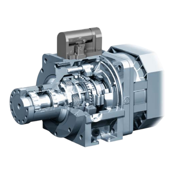
- Page 1 OPERATING INSTRUCTIONS ZF-DUOPLAN 2-Speed Gearbox 2K250 / 2K300...
- Page 2 Copyright © ZF Friedrichshafen AG This document is protected by copyright. Complete or partial reproduction or distribution of this document is not permitted without the approval of ZF Friedrichshafen AG. Infringements lead to civil and criminal prosecution.
-
Page 3: Table Of Contents
Contents 1 Preface ........................... 5 Validity and field of application ..................... 5 Consumables ..........................5 2 Safety ............................. 6 Signal words and symbols ......................6 General safety instructions ......................6 Product-specific safety instructions ....................8 ... - Page 4 Contents Lubrication ..........................29 4.6.1 Splash lubrication ........................29 4.6.2 Recirculating lubrication ......................29 4.6.3 Connections for lubrication ......................31 5 Initial Operation ........................34 Initial inspection ........................34 Checking setting dimension of sun gear ..................34 ...
-
Page 5: Preface
Preface Preface Validity and field of application In addition to the ZF documentation, observe the This documentation applies to the following ZF provisions of the body manufacturer. products: 2K250 2K300 Consumables Product Name/Specification Quantity Application Comment (approx.) Grease... -
Page 6: Safety
Safety Safety The following symbols are additionally used: This symbol refers to additional, safety- relevant information. Signal words and symbols This symbol indicates information This document contains specifically highlighted concerning special workflows, methods, safety instructions which are marked with one of application of auxiliary materials, etc. - Page 7 Safety Protect motor against being started accidentally. Observe the following points: Attach information sign in a clearly visible Employ authorized, trained and instructed staff. position. Observe technical provisions. Do not stand beneath a suspended load. Only use genuine ZF spare parts. ...
-
Page 8: Product-Specific Safety Instructions
Safety Product-specific safety instructions Remove any traces of old seals or gaskets from mating faces. Burrs or other similar rough surfaces are to be carefully removed with an oil stone. Carefully cover opened gearboxes to prevent the entry of foreign matter. EN 4161.758.102q –... -
Page 9: Application And Design
Application and Design Application and Design Application The DUOPLAN 2-speed gearbox by ZF is mainly used in machine tool drives. As a result of the different installation positions, the gearbox can be used, for example, for turning machines (horizontal B5) or machining centers (vertical V1). -
Page 10: Design
Application and Design Design The gearbox primarily comprises the following Output: assemblies: Bearing housing (9) Output bearing (10, 11) Connecting parts: Output shaft (12) Input hub (1) Radial shaft seal (13) Where required, adapter plate (2) with radial ... -
Page 11: Technical Data
Application and Design Technical data 2K250 2K300 2K250 2K300 Nominal power max. 39 kW max. 47 kW Input nominal max. 250 Nm max. 300 Nm, torque when i = 5.50 Nominal speed 1,500 rpm 1,500 rpm max. 250 Nm Max. speed Output torque, when ratio i1... -
Page 12: Installation Positions
Application and Design Installation positions Horizontal B5 Horizontal B5 Shift unit on right Gearbox rotated around longitudinal axis (looking at output) Vertical V1 Vertical V3 Possible damage to gearbox due to oil leaks. Fit breather at top in all installation positions. -
Page 13: Initial Installation
If oversized, the shaft must be machined to the correct length. Note the permissible axial forces on the motor shaft. Also refer to ZF-DUOPLAN catalog (4161.750.102), Chapter Performance data. EN 4161.758.102q – 2017-09... -
Page 14: Balancing
Initial Installation Balancing If using motors with parallel keys, note the balancing type. The hubs (2) are delivered with a keyway (1) to transmit power from the motor shaft (3) as standard. There are two balancing types for motor and gearbox: semi-key and full-key. -
Page 15: Motor Shafts/Hubs Without Keyways
Initial Installation 4.2.3 Motor shafts/Hubs without keyways Clamping hubs are available for motor shafts with diameters of 42 mm, 48 mm, 55 mm and 60 mm. Motor shaft EN 4161.758.102q – 2017-09... -
Page 16: Adaptation, Motor/Gearbox
120 °C from the A foot fastener is also available on the gearbox opening and slid onto the motor shaft until the housing for 2K250 and 2K300. stop is reached, using shim rings if required. Depending on the motor version, different gearbox Then check reference dimension "D". -
Page 17: Closed Design With Hub Bearing And Shaft Sealing Ring
Initial Installation 4.3.2 Closed design with hub bearing and shaft sealing ring Variant with ball bearing (4), containing additional bearing mounting for input hub (1), to prevent axial migration of the input hub. For assembly, separate input hub (1) with adapter plate (5) from gearbox housing (6). -
Page 18: Closed Design (With Shaft Seal)
Initial Installation 4.3.3 Closed design (with shaft seal) This variant contains an adapter plate (5) with shaft sealing ring (7), making the gearbox a compact, self-contained unit. Adapter plate and input hub (1) are delivered separately and loose. Clean the fitting surfaces of motor (3) and input hub. -
Page 19: Open Design With Adapter Ring
Initial Installation 4.3.4 Open design with adapter ring The adapter ring allows adaptation to different connecting dimensions. Sealing is required on the motor output shaft. Adapter ring (5) and input hub (1) are delivered loose. Clean the fitting surfaces of motor (3) and input hub. -
Page 20: Closed Design With Hub Bearing, Shaft Sealing Ring And Keyless Hub
Initial Installation 4.3.5 Closed design with hub bearing, shaft sealing ring and keyless hub When mounting on motor with smooth motor shaft without parallel key, ring clamping elements and pressure pieces must be used between motor shaft and input hub for torque transmission. A centric screw thread in the motor output shaft is absolutely essential. -
Page 21: Mounting The Gearbox
Initial Installation 4.3.6 Mounting the gearbox The M8 set screw (9) must be screwed in and tightened to 18 Nm until firmly home on the parallel key. Apply liquid seal to the set screw before installation. During assembly, ensure that the O-ring (10) is positioned correctly. -
Page 22: Version With Pulley Drive
Initial Installation 4.3.7 Version with pulley drive The pulley will be centred on the outer diameter of the drive flange (K6 tolerance), friction-locked in place and secured using screws, whereby the permitted torque must be taken into account. The pulley must have a balance rating of 6.3, as per VDI Directive 2060, in order to ensure low vibration operation. -
Page 23: Closed Design With Hub Bearing, Shaft Sealing Ring And Clamping Hub
Motor shaft Motor flange Mounting screw Clamping hub Sleeve Clamping screw Cover plate Output shaft Dimension A for extension of hexagon socket wrench Adapter plate 2K250, A = 100 mm Adapter plate 2K300, A = 125 mm EN 4161.758.102q – 2017-09... - Page 24 Initial Installation 4.3.8.1 Spindle cooling (TSC) version, feeding emulsions, hydraulic oils or air-oil mixtures Installing the rotary union: Mounting gearbox on motor: Apply grease to both ends of tube (5) and place in Coat thread of connecting piece (1) with sealing rotary union (4).
-
Page 25: Output
Initial Installation Output The warranty for the rotary union is limited to 12 months. Please note the details relating to the resultant Information regarding the product, function, force in the installation drawings. operation and installation of the rotary union can be found in the operating instructions 4.4.1 Version with belt output 4161.758.030 (German) - Page 26 Initial Installation Gearbox shift mechanism: Because of the different masses and associated drag torques of the spindle, the machine optimum During the gear change, the motor shaft is to be determined on the basis of shift tests. and/or gearbox output is without load The limit switch signals of S1 –...
- Page 27 Initial Installation Diagram for shift unit with two shifting positions (standard) or three shifting positions (with neutral position): Gear 1 ==> e.g. 4:1 Gear 2 ==> 1:1 Gear 3 ==> S3 neutral position, idling (option) blue grey optional black grey blue black black...
-
Page 28: Shift Logic
Initial Installation 4.5.2 Shift logic Decelerate main spindle motor from operating speed to zero. Keep controller release (signal) connected with power converter. Apply desired oscillating speed to converter and speed controller without delay. Shift unit energized (pin 2 and 3) Gear change Number of gear must be completed within 2... -
Page 29: Lubrication
In the 2K250/2K300 gearboxes, the V1 vertical and V3 vertical installation positions require recirculating lubrication. The type of recirculating Possible damage to gearbox due to insufficient lubrication depends on the operating temperature oil quantity and/or running dry. - Page 30 Initial Installation The following scenarios are unproblematic: The oil level in the tank falls during operation as a result of the gearbox oil in the gearbox foaming. The formation of an oil-air emulsion in the oil return and in the tank. 4.6.2.1 Recirculating lubrication during V1/B5 operation For the position of the oil inlets and outlets, refer...
-
Page 31: Connections For Lubrication
Initial Installation 4.6.3 Connections for lubrication 4.6.3.1 Connections for initial fill/ oil change Installation Oil fill Oil drain position G, F, H B5 rotated D, E by drawing off (for version with output shaft) (for version with output flange) EN 4161.758.102q – 2017-09... - Page 32 Initial Installation 4.6.3.2 Connections for recirculating lubrication in standard applications Installation Oil inlet connection Max. Oil return port position pressure M (0.5 l/min) and 0.5 bar (closed T (1.0 l/min) Main direction of 0.5 bar variant) rotation counterclockwise * T (1.5 l/min) 0.5 bar (open variant) Main direction of...
- Page 33 Initial Installation 4.6.3.3 Connections for integrated lubrication oil system and maximum speed For applications with a maximum speed of 10,000 rpm and/or a dry sump, the T connection with integrated lubrication oil system is mandatory. Furthermore, gearbox oil cooling >0.3 kW and a circulating oil volume >15 liters is required.
-
Page 34: Initial Operation
Initial Operation/Maintenance Initial Operation Maintenance Initial inspection Oil change Before initial operation, the correct installation Oil change interval: every 5,000 hours of condition of the gearbox must be checked. operation Mechanical fastening Motor flange-mounting Risk of burns due to contact with hot oil. ... -
Page 35: Repair
Repair Repair Questions for fault diagnosis: In the event of gearbox malfunctions, first check the connected components and their connections. Is oil level gage glass on gearbox dark/black? Carefully document the type of fault so as to assist Is there a smell of burning oil at the oil manufacturer diagnosis (refer to Chap. -
Page 36: Gearbox - Disassemble
Repair Gearbox – disassemble (e. g. version with adapter plate, shaft seal and hub bearings) Proceed accordingly in the case of other versions. Switch off the machine Switch off the power supply Disconnect the electrical connections Disconnect the gearbox oil connections, drain the gearbox oil ... -
Page 37: Disassembly Of Gearbox With Clamping Hub
Repair Disassembly of gearbox with clamping Note Chapter 7.2. Turn motor shaft (2) until clamping screw (7) can be seen through access bore in adapter plate (1). Loosen clamping screw. Loosen mounting screws (4) and pull gearbox off motor. Adapter plate Motor shaft Motor flange Mounting screw... -
Page 38: Frequently Asked Questions (Faq)
Frequently Asked Questions (FAQ) Frequently Asked Questions (FAQ) Error Cause of error Remedy Loose contact on motor speed Gearbox is loud, Check speed sensor and electrical knocking noises sensor. This causes permanent lines to motor, clean speed sensor if motor governing. - Page 40 ZF Friedrichshafen AG 88038 Friedrichshafen Deutschland · Germany Telefon/Phone +49 7541 77-0 Telefax/Fax +49 7541 77-908 000 www.zf.com...
Need help?
Do you have a question about the 2K250 and is the answer not in the manual?
Questions and answers