Table of Contents
Advertisement
Advertisement
Table of Contents

Summary of Contents for Fiplex DH7 Series
- Page 1 English DH7 Series - Digital Signal Booster User & Installation Manual...
- Page 2 Document History Description Revision Date Issued Original version Feb 17 , 2015 General Revision May 14 , 2015 UM-0821...
- Page 3 About this manual This manual describes installation, commissioning, operation and maintenance of Fiplex DH7 Series Digital Signal Booster, and Fiplex Control Software (FCS). The first part of the manual describes the Signal Booster hardware and the second part describes the software.
-
Page 4: Table Of Contents
Contents Part 1 HARDWARE ...................... 1 1. Safety ............................. 1 2. Product Description........................4 2.1. System Block Diagram........................ 5 2.2. Product Parts..........................6 2.3. Dimensions ..........................7 3. Installation ............................. 8 Mounting ............................8 Opening and Closing the Cabinet ....................11 Use of Liquid Tight Counduit...................... - Page 5 Extended Global System for Mobile communication ETACS Extended Total Access Communication System ETSI European Telecommunications Standard Institute Fiplex Control Software Global System for Mobile communication Hardware Light Emitting Diode Low Noise Amplifier, uplink and downlink Mobile Station, MS antenna = towards the mobile station...
-
Page 6: Part 1 Hardware
Part 1 HARDWARE Safety Dangerous Voltage Warning Any personnel involved in installation, operation or service of Fiplex Signal Boosters must understand and obey the following: The power supply unit in Signal Boosters supplied from the mains contains dangerous voltage level, which can cause electric shock. - Page 7 FCC Compliance This is a 90.219 Class B device. WARNING: This is a 90.219 Class B device. This is NOT a CONSUMER device. It is designed for installation by FCC LICENSEES and QUALIFIED INSTALLERS. You MUST have an FCC LICENSE or express consent of an FCC Licensee to operate this device. You MUST register Class B signal boosters (as defined in 47 CFR 90.219) online at www.fcc.gov/signal- boosters/registration.
- Page 8 The antenna/s used for this transmitter must be installed to provide a separation of at least 45 cm in DL and 45 cm in UL from all persons and must not be collocated or operating in conjunction with any other antenna or transmitter. Changes or modifications not expressly approved by the party responsible for compliance could void the user’s authority to operate the equipment.
-
Page 9: Product Description
Product Description. The DH7 Signal Booster Series are FPGA based Digital Channel Selective signal boosters that operates in the downlink frequency of 763-775MHz and in the uplink frequency of 793-805MHz for United States. For Canada it operates in the downlink frequency of 768-776MHz and in the uplink frequency of 798-806MHz. -
Page 10: System Block Diagram
2.1. System Block Diagram. The following image represents a general bock diagram of this Signal Booster. UM-0821... -
Page 11: Product Parts
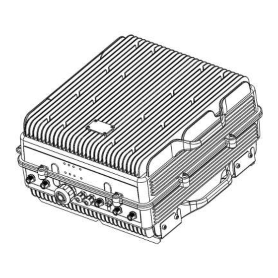
2.2. Product Parts. UM-0821... -
Page 12: Dimensions
2.3. Dimensions UM-0821... -
Page 13: Installation
Installation Mounting the Signal Booster Fiplex DH7 Signal Booster is designed for outdoor usage with a weather proof outdoor NEMA4 cabinet that can be mounted without any kind of shelter from rain, snow or hail. However, to improve reliability, it is recommended to mount the Digital Signal Booster on a site with shelter from direct exposure to sun, rain, snow and hailing. - Page 14 2. After attaching the bracket hang the Signal Booster as shown in Figure 3. Figure 3 UM-0821...
- Page 15 3. Secure the cabinet to the bracket as shown in Figure 4. To attach the Signal Booster’s cabinet to the bracket use the provided four M6 x 1/2” allen screws. Figure 4 UM-0821...
-
Page 16: Opening And Closing The Cabinet
Opening and Closing the Cabinet To open the cabinet, release the 8 door screws indicated in figure 5 using the provided special allen key. A - Release Signal Booster cover. Figure 5 Use the special allen key N°6 UM-0821... - Page 17 B - Open the Signal Booster cover. Figure 6 C – Close the Signal Booster cover. Figure 7 UM-0821...
- Page 18 D - Secure Signal Booster cover. Figure 8 UM-0821...
-
Page 19: Use Of Liquid Tight Counduit
Use of Liquid Tight Counduit The unit has available a Liquid Tight Conduit Fitting connector for ¾” tubes. The unit as standard has the connector installed, so if the user requires to use this connector, if available, the NFPA cables, Ethernet, DC or AC cables can be routed through this connector. Figure 9;... - Page 20 B – Install the sealing cup Figure 10; Replacement of Conduit connector to sealing cup UM-0821...
-
Page 21: Commissioning
Commissioning 4.1. Connection step by step Figure 11 Figure 11; RF ports and Power Cable Glands location. Connect service antennas to the To Mobile Port. N type female connectors are used in the Signal Booster. Connect the donor antenna to the To Base RF Port. N type female connectors are used in the Signal Booster. - Page 22 Figure 12 If the Signal Booster has the NFPA Option, there is a dedicated cable gland for this purpose (“NFPA” in figure 11). A multi-conductor cable can be used to connect the NFPA dry contacts to the Fire Department Control Box. Status of contacts (Alarms Off) Pin 1 –...
- Page 23 5. Once the Signal Booster is connected to the power source, it takes about 40 seconds to run a booting routine. After that time, the Signal Booster is ready to be connected via USB cable to a computer running Fiplex Control Software (FCS) to be properly configured. Figure 15; USB port location...
-
Page 24: Starting Operation
Turn on the Digital Signal Booster, connect computer to Signal Booster through USB cable, and run Fiplex Control Software. It is recommend to turn off the power amplifiers. Setup desired channel frequencies. Since Fiplex Signal Booster is channel selective, user has to know what frequencies are used in base station. - Page 25 Setup desired operating gain using FCS. UL and DL chain are independent, so both values must be set. To set DL band gain is recommended that AGC works around 3 - 6dB in each channel, in this way, maximum output power is achieved. Set up squelch settings.
-
Page 26: Status Indicators
Status Indicators There is an indicator panel located at bottom of the Signal Boosters door. This led panel works as a status monitor, in order indicate warning or alarms of Signal Booster. The LED panel has four LEDs, the first one the power ON indication led, labelled “PWR”. The Second LED, labelled “STS”... - Page 27 The third and fourth LED summarizes operational conditions for uplink “UL” and downlink “DL” chains. In general, the LEDs have four states: “off”, “slow blinking”, “fast blinking” and “on”. Table 1 describes alarm and warning conditions for each led state. Table 1 Indicator Panel LED indication description...
-
Page 28: Laboratory Measurements
Laboratory Measurements For specific parameters verification and laboratory tests, please contact factory. Detailed procedures, recommended tests set up, and a knowledge engineering team will bring adequate support to perform this measurements in a comfortable and safely way UM-0821... -
Page 29: Part 2 Software
Local Software. Desktop application through USB port 2.1. Installation The following section will describe the steps to be followed in order to install and use the Fiplex Control software with your Fiplex Signal Booster. 1. Before connect USB cable between computer and Signal Booster, run the FiplexControlSoftware.msi File. - Page 30 3. The installer will start to copy the necessary files. 4. After installation has completed, a shortcut in user desktop will appear. UM-0821...
- Page 31 C:\Program Files (x86)\FiplexControlSoftware\drivers”. 6. Turn on the Signal Booster BE SURE THAT “TO MOBILE” AND “TO BASE” PORTS ARE PROPERLY LOADED EITHER WITH 50 OHMS DUMMY LOADS, OR RADIATING SYSTEM. 7. Execute the Fiplex Control Software. Next window will appear: UM-0821...
- Page 32 File menu: contains menus to save Signal Booster configuration to a file and load configuration from file to Signal Booster. NOTE: if Fiplex Signal Booster is not turned on, related COM port will appear as “Unknown device” 8. Click “Scan Devices”...
- Page 33 Now, the Fiplex Digital Signal Booster is shown in the list of available devices, and connection button is enabled. NOTE: Fiplex Signal Booster could not appear in list, if COM port number is higher than COM16, depending on Windows version. COM port number can be forced to arbitrary number (below COM16) through Device Administrator.
- Page 34 Change COM port number 9. Click “Connect”. Fiplex Control Software window will be automatically maximized, and web browser will show the configuration screen. Application screens are described in the next section due to these application screens and web pages (in webserver remote mode) are the same.
-
Page 35: Remote Web Server Option
10. Once Signal Booster is configured, user can disconnect software using connection button, now labelled “Disconnect”. Initial window will be shown. If Signal Booster is disconnected or turned off, while Fiplex Control Software is connected to device, software will go back to initial window. Moreover, if some communication problem occurs while device is monitored, the software will go back to initial state as well. - Page 36 NOTE: in order to restore password, push the button placed close to USB Connector during 5 seconds. After authentication, web browser will load the main page of Fiplex Signal Booster showing RF configuration and monitoring parameters. At left side of webpage, configuration menus are shown: ...
- Page 37 Tag: user can set a tag to ease Signal Booster identification. For modifying the TAG, write a new value in text field and click over Apply Changes link IP: At this page, Signal Booster IP address, network submask, gateway address and IP addresses of SNMP Managers are shown.
- Page 38 Date and Time: page to modify real time clock. When the Signal Booster is not powered, this clock runs with a voltage supply provided by a 3V lithium battery, button type of 20mm (CR2032) with 220mA·h. This suffices for at least half year. When the Signal Booster is powered, no current is drained from the battery.
-
Page 39: Rf Parameters Description
Configuration Apply Changes: as it is said above, this link is used to load changes to the Signal Booster, in configuration, tag, IP, password and date and time menus. After any configuration change, web page will show and icon that allows user to know if configuration has been successfully applied: Reload Settings: clicking this link, Signal Booster configuration data is refreshed. - Page 40 Frequency control: this section contains fields to modify channel frequencies. Frequency resolution is 6.25KHz. User can change any channel frequency, taking into account that uplink and downlink frequencies are always separated 45MHz. Display check-boxes column are used to display each channel control frame, by default, only active channels will be displayed.
- Page 41 Main downlink control: parameters regarding to downlink band. They are almost equal to uplink band. Parameter Range Description Gain control 60dB to 85dB Set maximum gain of Signal Booster at DL band Set maximum output power of Signal Booster at DL band.
- Page 42 Channel control frame: shows configuration and monitoring information of each channel. The frame is divided in two: uplink and downlink. Data showed in each half is symmetric. Parameter Range Description Fine gain control -10dB to 0dB Each channel gain can be fine adjusted Fine power limit Each channel maximum output power can be -10dB to 0dB...
Need help?
Do you have a question about the DH7 Series and is the answer not in the manual?
Questions and answers