Table of Contents
Advertisement
Advertisement
Table of Contents

Summary of Contents for Teac TD-260T
- Page 1 D01156700E Digital Transducer Indicator TD-260T Instruction Manual...
-
Page 2: Introduction
Introduction Thank you for purchasing the TD-260T digital transducer Checking Accessories indicator (“TD-260T”). Please read this document in its entirety before using the product to get the best performance and If anything is missing or damaged, contact us. (For contact ensure safe and proper operation. -
Page 3: Safety Instructions
Safety Instructions This document describes the safety instructions for the operation of the TD-260T. Before operating the product, read this document carefully to familiarize yourself with the product. Warning Follow the instructions below to avoid risk of serious personal injury and death. -
Page 4: Table Of Contents
Table of Contents Introduction ..................... 2 7. Setting Functions ...................30 Features ......................... 2 7-1. Setting HI, LO, HH, and LL values ............30 7-1-1. Statuses of decision output LEDs ..........30 Checking Accessories .................... 2 7-1-2. HI value..................... 30 Safety Instructions ..................3 7-1-3. - Page 5 11-9. Set-value retrieval command ............64 11-10. Control Commands ................65 11-11. Format for transmission mode 1 ..........65 12. D/A Converter (TD-260T AC(D/A) / TD-260T DC(D/A)) ..66 12-1. Panel ......................... 66 12-2. Connections ....................66 12-2-1. Connecting to screwless terminal block ......66 12-3.
-
Page 6: Controls And Functions
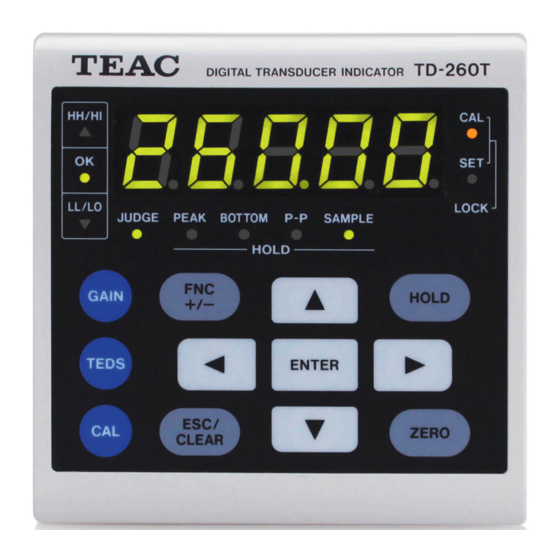
Pattern and “0” for Hysteresis are selected. 1 Numeric display 3 Decision LED (JUDGE) The TD-260T shows a continuous reading or a set value on The LED lights when the decision output is enabled. the display. With Enable JUDGE Signal (F3-8) set to ON;... - Page 7 ESC/CLEAR: Pressing this key while the setup screen is displayed cancels the setting, and then displays a reading again. Pressing the key while the TD-260T is in a hold mode clears the hold value. ENTER: Pressing this key saves the item or value you have set.
-
Page 8: Rear Panel
Connects a strain gage sensor or TEDS sensor remote sense). 5 Option space < The wiring colors shown are those of TEAC strain gage The optional NDIS panel (PN-260ND) can be installed in this sensors. area. (Because the option-installed model has an option board pre-installed in this area, the optional panel cannot be installed in the option-installed model.) -
Page 9: Control I/O Terminal Block
The function is enabled only while both CAL Lock (F3-5) and Enable Digital Zero (F3-1) are ON. When the TD-260T is turned off, the digitally set zero is cleared. This is the common terminal for A5, Common terminal for B8 A6, A7, and A8. -
Page 10: Hardware Installation
2. Hardware Installation 4. Put the guide rails that were removed in Step 2, back Follow these steps to install the TD-260T inside a control panel. in place from the rear side, and then secure them 1. Cut out the panel according to the dimensions in the with the two screws. -
Page 11: Connections
4. Lightly pull each wire and make sure that they are 5. Plug the wired connector into the terminal block in securely clamped. the TD-260T, and then secure the connector plug to the terminal block with the screws. 5. Plug the wired connector into the terminal block in the TD-260T, and then secure the connector plug to the terminal block with screws. -
Page 12: Connecting Strain Gage Sensor
(-SIG) temperature. For applications of the TD-260T that may be exposed to varying temperatures including the use of the device in an (-EXC) outdoor installation system, or applications of the TD-260T... -
Page 13: Connecting To Power Input Terminals, Fg Terminal, And Protective
Black White Green/yellow < If you want to use the TD-260T as a CE compliant unit, the length of the power cord to be used for the TD-260T must be 3 m or less. < Power cord wire colors (for the provided AC power cord) Black <... -
Page 14: Connecting To Control I/O Terminals
3. Connections 3-4-2. Connecting decision outputs 3-4. Connecting to control I/O terminals TD-260T Diode 3-4-1. Connecting external input Load An input signal is generated from an external input circuit when a control terminal and COM terminal on the external input circuit are short-circuited and then opened. -
Page 15: Setup Mode
F1-1, for example. To change a set value, you need to put the TD-260T into the corresponding setup mode by displaying the appropriate setup screen number and then pressing ENTER. -
Page 16: List Of Setup Items And Settings
4. Setup Mode 4-2. List of setup items and settings 4-2-1. F1 setup screens x: Applicable Setup Setup item name Initial screen Setting range Page Unit setting Lock Lock Displayed text number HI value F1-1 150.00 -19999 to 9999 LO value F1-2 050.00 -19999 to 99999... -
Page 17: F2 Setup Screens
4. Setup Mode 4-2-2. F2 setup screens x: Applicable Setup Setup item name Initial screen Setting range Page Unit setting Lock Lock Displayed text number 0.OFF: Disable hold 1.SPL: Sample hold Hold Mode F2-1 1.SPL 2.PEk: Peak hold 3.bot: Bottom hold 4.P2P: Peak-to-Peak hold Digital Offset F2-2... -
Page 18: F3 Setup Screens
4. Setup Mode 4-2-3. F3 setup screens x: Applicable Setup Setup item name Initial screen Setting range Page Unit setting Lock Lock Displayed text number Enable Digital Zero F3-1 OFF, ON Enable Block Setting F3-2 OFF, ON Minimum Scale F3-3 1, 2, 5, 10 Display Refresh Rate # of... -
Page 19: F4 Setup Screens
4. Setup Mode 4-2-4. F4 setup screens x: Applicable Setup Setup item name Initial screen Setting range Page Unit setting Lock Lock Displayed text number # of BCD Data Refresh Rate F4-1 1, 2, 5, 10, 20, 50, 100 times /sec BCD Output Check F4-2... -
Page 20: Error Messages
5. Error Messages ADC overflow in the positive direction ADC overflow in the negative direction Display overflow in the positive direction (higher than 99999) Display overflow in the negative direction (lower than -19999) Input higher than 3.2 mV/V Input lower than -3.2 mV/V •... -
Page 21: Calibration
TD-260T. the TD-260T and then turn it on. In that case, set the TD- 260T to the static strain mode by performing Static Strain 1. -
Page 22: Common Calibration Procedure
6-1-1. Enabling and disabling CAL lock 6-1. Common calibration procedure Normally the TD-260T is used with the calibration lock set to ON. Be sure to set the calibration lock to OFF before calibration, The three calibration methods available in the TD-260T, and then set it to ON again after calibration. -
Page 23: Remote Sense/Teds
You need to set the terminals to one of the available settings remote sense). before connecting a sensor to the TD-260T. < If you use neither remote sense nor TEDS sensor, be sure to 1. Enter the setup screen number F2-6. -
Page 24: Bridge Voltage
6. Calibration 6-1-3. Bridge voltage 6-1-4. Minimum scale You need to set the bridge voltage, which is supplied to a You can set the minimum increment value that is used to strain gage sensor. display a change in the digital reading. 1. -
Page 25: Display Refresh Rate
6. Calibration 6-1-5. Display Refresh Rate 6-2. Equivalent input calibration You can select the display refresh rate per second for a reading. 1. Enter the setup screen number F3-4. You can determine the calibration values by setting the rated output and rated capacity shown on the test report. Using this calibration method, you can easily perform a Press 3 times calibration without applying an actual load. - Page 26 NOTE The position of the decimal point you set in this step is used for readings on the TD-260T. 5. To save the rated capacity you entered, press ENTER. CAUTION If you use the D/A option, the rated capacity is set as the D/...
-
Page 27: Actual Load Calibration
The position of the decimal point you set in this step is used with no load on the sensor, press ZERO, and then for readings on the TD-260T. press ENTER. 4. To save the rated capacity you entered, press ENTER. -
Page 28: Teds Calibration
The position of the decimal point you set in this step is used change the blinking digit of the value by pressing 5 for readings on the TD-260T. or b . 4. To save the rated capacity or the change you made, To move to the previous or next digit, press g or t . -
Page 29: Displayed Digits Of Rated Capacity For Teds Calibration
< If Remote Sense/TEDS (F2-6) is set to a value other than NOTE 2.rSEn, and a TEDS sensor is not connected to the TD-260T, “Err06” appears on the display, followed by a reading. You can set the sensor input of up to +2 or down to -2 mV/V to zero. -
Page 30: Setting Functions
7. Setting Functions 7-1-2. HI value 7-1. Setting HI, LO, HH, and LL values 1. Enter the setup screen number F1-1. You can set HI, LO, HH, and LL values, compare each with a reading, and then generate each decision output so that a comparison result is determined. -
Page 31: Lo Value
7. Setting Functions 7-1-3. LO value 7-1-4. HH value 1. Enter the setup screen number F1-2. 1. Enter the setup screen number F1-3. Press once Press once Press once Press twice 2. To change the blinking digit of the value, press 5 or b . 2. -
Page 32: Ll Value
7. Setting Functions 7-1-5. LL value 7-1-6. Enable HH and LL You can enable or disable HH and LL decision outputs. 1. Enter the setup screen number F1-4. If you select OFF, the HH or LL or Low-Low limit decision output is not generated anymore, and the HH/HI or LL/LO LED Press once display solid red instead to show that the HI or LO decision... -
Page 33: Hysteresis
7. Setting Functions 7-2. Hysteresis Using this function, You can buffer the set points at which the HH, HI, LO, and LL decision outputs switch off. If fluctuations in the reading occur near each comparative point, the corresponding decision output switches on and off, which is a phenomenon called “chattering.”... -
Page 34: Comparative Output Pattern
7. Setting Functions 1. Enter the setup screen number F1-6. 7-3. Comparative Output Pattern Press once The following two operating settings for decision outputs are available: standard output and area output. Press 5 times 7-3-1. Standard output Each decision output switches on when the following conditions are met. -
Page 35: Area Output
7. Setting Functions 7-3-2. Area output 1. Enter the setup screen number F1-15. Each decision output switches on when the following conditions are met. Press once (with hysteresis set to 0) HH: HH value < reading Press once HI: HI value < reading < HH value LO: LL value <... -
Page 36: Comparison Mode
7. Setting Functions 7-4. Comparison Mode 7-5. Near Zero You can set a condition for comparing a reading with HI, LO, You can set a range to be considered near zero. HH, and LL values and determining the comparison result. 1. -
Page 37: Motion Detection
If the difference between the currently displayed reading and the reading that was displayed 100 milliseconds ago is equal to or lower than the bandwidth you set, and then the state remains unchanged for more than the length of set time, the TD-260T determines that the currently displayed reading is stable. -
Page 38: Zero Tracking
7. Setting Functions 7-7. Zero tracking Using zero tracking automatically tracks and corrects deviations from zero point, such as drift. If a drift is within the bandwidth you set, the function automatically moves a drifted zero point to zero at each set time interval. Zero tracking is enabled only while both CAL Lock (F3-5) and Enable Digital Zero (F3-1) are set to ON. -
Page 39: Digital Filter
7. Setting Functions 7-8. Digital Filter 7-9. Analog Filter You can select a number of measurements to be used for You can select a cutoff frequency (Hz) of the low-pass filter. obtaining a moving average. 1. Enter the setup screen number F2-4. 1. -
Page 40: Set Lock
< To exit the static strain mode, select OFF while the above screen is displayed, or shut off the power to the TD-260T, and then turn it on again. < The TD-260T uses one strain gage with a gauge factor of 2.0 to display static strain. -
Page 41: Decision-Output Check
By using this function, you can check wiring of each decision JUDGE, and CLEAR signals. output. Note that the TD-260T does not work as an indicator while the 1. Enter the setup screen number F4-9. function is enabled. Press 4 times 1. -
Page 42: Beep
You can turn on or off the beep sound that you normally hear You can select the data to be sent from the BCD parallel data when you press a key on the TD-260T. output, the RS-232C serial data output, or the D/A converter, which can be installed in the option space. -
Page 43: Hold Function
8. Hold function 8-1. Hold Mode 8-2. External Hold Mode The following hold modes are available: Sample, Peak, Bottom, You can select a signal type for the HOLD signal from the and Peak-to-Peak. control input/output terminal A7. 1. Enter the setup screen number F2-1. 1. -
Page 44: Enable Clear Signal
8. Hold function 8-3. Enable CLEAR Signal 8-4. Enable Block Setting You can enable or disable the CLEAR signal from the control 1. Enter the setup screen number F3-2. input/output terminal A5 and the ESC/CLEAR key. 1. Enter the setup screen number F2-8. Press 3 times Press twice Press once... -
Page 45: Enable Judge Signal
8. Hold function 8-5. Enable JUDGE Signal You can disable or enable the signal that controls the decision outputs. 1. Enter the setup screen number F3-8. Press 3 times Press once 2. To select OFF or ON, press 5 or b . OFF: Always enable decision outputs ON: Enable decision outputs while the JUDGE signal is ON 3. -
Page 46: Sample Hold
8. Hold function 8-6. Sample hold You can put the TD-260T into the Sample hold mode by using the HOLD key or setting the HOLD signal from the control input/ output terminal A7 to ON. If the HOLD key is pressed, the TD-260T starts holding the displayed reading, and then if the HOLD key is pressed again, the TD-260T exits the hold mode. -
Page 47: Peak Hold
A7 is set to OFF, the TD-260T exits the Peak hold mode, and then starts measuring the input signal again. If the CLEAR key is pressed or the CLEAR signal from the control input/output terminal A5 is set to ON while the TD-260T is in the hold mode, the TD-260T resets the peak value. -
Page 48: Bottom Hold
A7 is set to OFF, the TD-260T exits the Bottom hold mode, and then starts measuring the input signal again. If the CLEAR key is pressed or the CLEAR signal from the control input/output terminal A5 is set to ON while the TD-260T is in the hold mode, the TD-260T resets the bottom value. -
Page 49: Peak-To-Peak Hold
A7 is set to OFF, the TD-260T exits the Peak-to-Peak hold mode, and then starts measuring the input signal again. If the CLEAR key is pressed or the CLEAR signal from the control input/output terminal A5 is set to ON while the TD-260T is in the hold mode, the TD-260T resets the peak-to-peak value. -
Page 50: Digital Zero Function
To save, press: CAUTION If the current sensor input exceeds the digital zero limit setting, the TD-260T, which regards as zero the sensor input that was obtained when the zero-point calibration was performed, shows Err14, meaning digital zero limit error, and cannot set the displayed reading to zero. -
Page 51: Clear Digital Zero
Digital Zero was performed. digitally set to zero if you press ZERO or short-circuit the After this function is performed, the TD-260T displays the control input/output terminals A8 for D/Z and A9 for COM. current sensor input value, regarding as zero the sensor 1. -
Page 52: Digital Offset
9. Digital Zero Function 9-5. Digital Offset You can set a value that is automatically subtracted from a measured value. (Tare) 1. Enter the setup screen number F2-2. Press twice Press once 2. To change the blinking digit of the value, press 5 or b . To move to the previous or next digit, press g or t . -
Page 53: Bcd Data Output (Td-260T Ac(Bcd) / Td-260T
10. BCD Data Output (TD-260T AC(BCD) / TD-260T DC(BCD)) The BCD data output is an interface for sending the TD-260T 1 BCD connector displayed readings as BCD-coded data. The interface connects Signal name Signal name the TD-260T to a computer, process controller, sequencer or equivalent, for controlling, summarizing, recording or any other processing purposes. -
Page 54: Changing Logic
10.BCD Data Output (TD-260T AC(BCD) / TD-260T DC(BCD)) 10-2. Changing logic 10-3. Equivalent circuit You can change the logic setting for all output signals except Output equivalent circuit for the STROBE signal. TD-260T If a COM terminal and the pin 28 are open, the signals are set to negative logic. -
Page 55: Signal Timing
10.BCD Data Output (TD-260T AC(BCD) / TD-260T DC(BCD)) 10-4. Signal timing P.C (stable) The P.C signal is turned on when the input signal is stable. To load the BCD data in synchronization with the STROBE signal, be sure to wait 25 milliseconds or more after the falling edge of the P.C signal. -
Page 56: Bcd Data Refresh Rate
Press 4 times Press once 2. To select 100, 50, 20, 10, 5, 2, or 1, press 5 or b. 2. The TD-260T goes into check mode, with AAAAA being both displayed on the TD-260T and sent from the BCD data output. -
Page 57: Rs-232C Interface (Td-260T Ac(232C) / Td-260T
11. RS-232C Interface (TD-260T AC(232C) / TD-260T DC(232C)) The RS-232C interface loads readings and states from and also 11-2. Standard saves set values into the TD-260T. It connects the TD-260T to a computer, process controller, sequencer, or equivalent, for Signal level:... -
Page 58: Cable Wiring Example
11. RS-232C Interface (TD-260T AC(232C) / TD-260T DC(232C)) 11-3. Cable wiring example 11-4. RS-232C Interface Setting You can change the RS-232C transmission conditions: TD-260T Computer etc. 1. Enter the setup screen number F4-3. Signal Signal Press 4 times Press twice... -
Page 59: List Of Commands
11. RS-232C Interface (TD-260T AC(232C) / TD-260T DC(232C)) 11-5. List of Commands 11-5-1. Read commands Command Function Page Load displayed readings Load statuses Load statuses 11-5-2. Set commands Command Setup item Page Unit Lock Lock HI Valuet LO Value Comparison Mode... -
Page 60: Set-Value Retrieving Set Value
11. RS-232C Interface (TD-260T AC(232C) / TD-260T DC(232C)) Command Setup item Page Unit Lock Lock CAL Lock SET Lock Minimum Scale Display Refresh Rate # of times Bridge Voltage External Hold Mode Remote Sense/TEDS Enable CLEAR Signal Enable Block Setting... -
Page 61: Transmission Mode
0: OFF decision A host computer sends data called Request to the TD-260T, 1: ON output and then the TD-260T sends data called Response back to the 0: OFF LL decision host computer. Request and Response use ASCII characters output 1: ON except for CR and LF. -
Page 62: Set Commands
11. RS-232C Interface (TD-260T AC(232C) / TD-260T DC(232C)) HH Value (W07) 11-8. Set commands W 0 7 0 0 0 0 0 0 CR LF HI Value (W01) sign bit W 0 1 0 0 0 0 0 0 CR LF... - Page 63 11. RS-232C Interface (TD-260T AC(232C) / TD-260T DC(232C)) Zero Tracking Bandwidth (W16) External Hold Mode (W25) W 1 6 0 0 0 0 0 0 CR LF W 2 5 0 0 0 0 0 0 CR LF Set value without decimal point...
-
Page 64: Set-Value Retrieval Command
11. RS-232C Interface (TD-260T AC(232C) / TD-260T DC(232C)) D/A Zero Setting (W33) 11-9. Set-value retrieval command W 3 3 0 0 0 0 0 0 CR LF You can retrieve a set value by using the following command. sign bit... -
Page 65: Control Commands
11. RS-232C Interface (TD-260T AC(232C) / TD-260T DC(232C)) 11-10. Control Commands 11-11. Format for transmission mode 1 Hold ON (CE) The TD-260T continuously transmits 20-byte data in the following format. C E CR G S , , ± 0 0 0 0 0 0 CR LF (Only with a hold mode setting other than 0.OFF enabled) -
Page 66: D/A Converter (Td-260T Ac(D/A) / Td-260T Dc(D/A))
12. D/A Converter (TD-260T AC(D/A) / TD-260T DC(D/A) ) The D/A output circuit is isolated from the TD-260T internal 12-2. Connections circuit. The analog output ranges are 0 to ± 10 V in voltage and 4 to Connect an external device with a load resistance of 2 kΩ or 20 mA in current. -
Page 67: D/A Zero
12-3. D/A Zero 12-4. D/A Full Scale You can set a value so that the TD-260T generates a D/A zero You can set a value so that the TD-260T generates a D/A full output (voltage 0 V and current 4 mA) when it displays the scale output (voltage 10 V and current 20 mA) when it displays same reading as the value you set. -
Page 68: D/A Output Error
12. D/A Converter (TD-260T AC(D/A) / TD-260T DC(D/A) ) Setting example 1 12-5. D/A output error D/A Zero 000.00 Below are the messages that are displayed when errors are D/A Full Scale 100.00 caused by the D/A option. Reading D/A Output dErr: the D/A output is higher than +10.9 V. -
Page 69: Ndis Panel (Pn-260Nd)
TEDS sensor, do not connect any device to the terminal F or < If you connect a sensor to the NDIS connector on the panel, do not connect any sensor to the signal input/output terminal block on the TD-260T. 1 NDIS connector Pin assignmentment... -
Page 70: About Teds
TD- 260T and use the values for calibration with the TD-260T. You can also use the TD-260T to save on your TEDS sensor values that are used for calibration with the TD-260T or to restore the TEDS sensor's factory settings. -
Page 71: Restore Teds Data
NOTE If you press ESC while “tEdS” is not displayed, the setting is interrupted, and then the TD-260T exits the setup mode. 5. The rated capacity is displayed. Check the value, and 2. To enter 00015, change the blinking digit of the then press ENTER. -
Page 72: Available Functions At Turn-On
15. Available functions at turn-on 6. The TD-260T displays the following message during You can check operations of the TD-260T when turning it on. the TEDS check process. 15-1. Performing self-check This function allows the TD-260T to perform a self-diagnostic check of LEDs, RAM, SRAM, EEPROM, and TEDS, in this order. -
Page 73: Specifications
Approx. 96 mm x 96 mm x 146 mm (protrusions not included) Weight Approx. 950 g Option (Not used for option-installed models) NDIS panel (PN-260ND) Option-installed models TD-260T AC(BCD) / TD-260T DC(BCD) TD-260T AC(232C) / TD-260T DC(232C) TD-260T AC(D/A) / TD-260T DC(D/A) -
Page 74: Outline Drawings
17. Outline drawings Dimensional drawing of panel cut-out (recommended panel thickness: 1.6-3.0 mm) Panel cut-out +0.8 Standard: DIN IEC61554, published in 2002 < Specifications and appearance are subject to change for improvement without notice. < Some of the images shown in this document may differ from the actual product for product improvement. -
Page 75: Block Diagram
18. Block Diagram Bu er Analog output Strain gage ampli er Gain regulator Filter circuit Voltage shift circuit circuit Bridge power Zero regulator supply circuit conversion TEDS Reference memory voltage line LED indicator F F .G TEDS AC power type EEPROM RS232C +12V... - Page 76 TEAC CORPORATION 1-47 Ochiai, Tama-shi, Tokyo 206-8530 Japan Sales Section, Measurement Products Department, Information Products Division Phone: +81 - 042 - 356 - 9161 , Fax: +81 - 042 - 356 - 9185 Website http://www.teac.co.jp/industry/measurement/index.html < Addresses and telephone numbers are subject to change without notice.
Need help?
Do you have a question about the TD-260T and is the answer not in the manual?
Questions and answers