Table of Contents
Advertisement
Quick Links
Advertisement
Table of Contents

Related Manuals for Sportable Scoreboards 1232 LED

Summary of Contents for Sportable Scoreboards 1232 LED
- Page 1 INSTALLATION INSTRUCTIONS MODEL 1232 LED www.sportablescoreboards.com...
-
Page 2: Table Of Contents
Table of Contents INSTRUCTIONS FOR REPORTING SHIPPING DAMAGE ................. 3 PRODUCT SPECIFICATIONS ..........................4 Overall Dimensions: ............................4 Weight: ..................................4 Power Requirements: ............................4 Communication Cable Requirements (for cable-controlled systems only): ......5 DETERMINING LOCATION AND ORIENTATION ..................5 INSTALLING MOUNTING POLES OR I-BEAMS ................... -
Page 3: Instructions For Reporting Shipping Damage
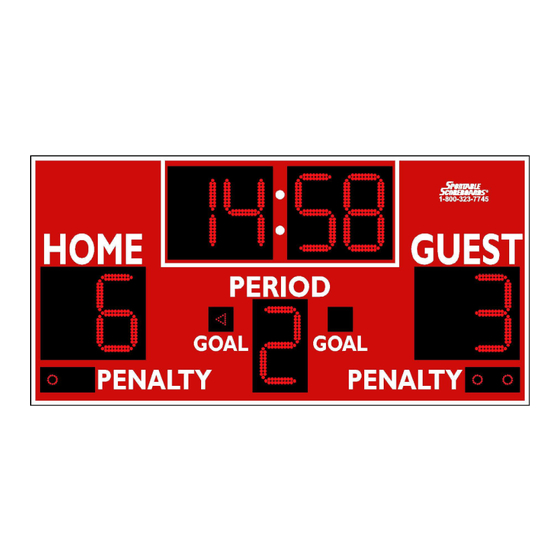
DESCRIPTION MODEL 1232 LED 4’ X 8’ OUTDOOR SCOREBOARD NOTE TO INSTALLERS: PLEASE RETURN THIS MANUAL TO THE INDIVIDUAL IN CHARGE OF THE SCOREBOARD UPON COMPLETION OF INSTALLATION. The scoreboard and all accompanying accessories have been carefully inspected and tested before leaving the factory. -
Page 4: Product Specifications
If damage is discovered after delivery, call the delivery company to report the concealed damage and please call the manufacturer immediately to report. Concealed damage must be reported within 5 days after the delivery date. If the damages are found after this time, the manufacturer will not be responsible. -
Page 5: Communication Cable Requirements (For Cable-Controlled Systems Only)
Communication Cable Requirements (for cable-controlled systems only): Four conductor cable – 28 gauge, twisted pair (two pairs), shielded data cable. DETERMINING LOCATION AND ORIENTATION The scoreboard should be positioned so that the greatest number of spectators can easily view it. Also, consider the best orientation of the scoreboard should the system be used to score a daytime or afternoon game. - Page 6 dimensions for the footers vary depending on local building codes, soil & weather conditions, and scoreboard size. Consult with local building officials for the required pole sizes and footer construction regarding this installation. A local architect, structural engineer, or sign installer may also be a source of assistance.
-
Page 7: Running & Connecting The Control Cable
RUNNING & CONNECTING THE CONTROL CABLE (For scoreboards with Wireless Remote Control, skip this step.) The control cable must be run in a separate conduit than is used for the electrical service. The control cable should run from the scoreboard to a location that is within 10 feet of the scorekeeper’s location and into a 2”X4”... -
Page 8: At The Scoreboard
back of the wall plate. Follow the chart if possible, but more importantly; whatever the match- up is at the wall plate should also be the match-up at the scoreboard. 3. Secure the junction box cover to the installed junction box. At the scoreboard: 4. -
Page 9: Testing The Installed System
AFTER EACH USE, THERE SHOULD BE EASY ACCESS TO THE POWER SWITCH OR CIRCUIT BREAKER. IF ACCESS TO THE CIRCUIT BREAKER IS NOT AN OPTION, INSTALL A SWITCH SOMEWHERE THAT IS ACCESSIBLE, EVEN IF UNDER THE SCOREBOARD AT AN ABOVE AVERAGE HEIGHT. - Page 10 NOTE: To activate your warranty, your check off sheet must be signed and returned/faxed to Sportable Scoreboards Inc. A copy of this sheet should be placed with your Installation/Operators Manual in the event technical support is needed. Fax number (270) 753-3773.
-
Page 11: Important
IMPORTANT! Warranty Activation/Installation & Completion Sign Off Sheet NOTE: This sheet must be completely filled out and returned/faxed (270) 753-3773 to Scoreboard Service Company before your warranty can be activated. Your Serial Number _______________________________________ Your Model Number _______________________________________ Date Purchased _______________________________________ Sales Agent _______________________________________...
Need help?
Do you have a question about the 1232 LED and is the answer not in the manual?
Questions and answers