Sign In
Upload
Download
Table of Contents
Contents
Add to my manuals
Delete from my manuals
Share
URL of this page:
HTML Link:
Bookmark this page
Add
Manual will be automatically added to "My Manuals"
Print this page
×
Bookmark added
×
Added to my manuals
Manuals
Brands
Kanga Manuals
Compact Loader
PW628
Operator's manual
Kanga PW628 Operator's Manual
Mid range loader
Hide thumbs
1
2
3
4
5
6
7
8
9
10
11
Table Of Contents
12
13
14
15
16
17
18
19
20
21
22
23
24
25
26
27
28
29
30
31
32
33
34
35
36
37
38
39
40
41
42
43
44
45
46
47
48
49
50
51
52
53
54
55
56
57
58
59
60
61
62
63
64
65
66
67
68
69
page
of
69
Go
/
69
Contents
Table of Contents
Troubleshooting
Bookmarks
Table of Contents
Revision Table
Delivery Sheet
Warranty Registration Card
Loader Checklist
Serial Number Registration
Warranty Details
Foreward
Table of Contents
How to Contact Us
Safety
Preparation for Use
Safety Label Identification
Safe Operation
Five Steps to Effective Jsea
No Go Zones for Underground Utility Services
OPERATOR SAFETY - Summary
Task Planning for the Kanga Loader
Pre-Operational Risk Assessment
Risk Assessment
Operating Instructions
Attachments
Hydraulic Attachment Connections
In 1 Operating Instructions
Power Head Operating Instructions
Trencher Operating Instructions
Back Hoe Operating Instructions
Bucket Broom Operating Instructions
Rotary Hoe Operating Instructions
SAFETY - Rules for Attachments
Maintenance
Daily Operator Maintenance
OPERATOR MAINTENANCE - Safety Checks
Loader Arm Maintenance
Service Tasks
SERVICE TASKS - Engine
SERVICE TASKS - Hydraulics
SERVICE TASK - Trenching Valve
SERVICE TASKS - Visual
SERVICE TASKS - Grease Nipple
SERVICE TASK - Radiator (Diesel)
SERVICE TASKS - Battery
SERVICE TASKS - Pivot Pins
SERVICE TASKS - Tyre Pressure
Decals
Service Chart
Maintenance Schedule
Specification
SPECIFICATIONS - MID Range Loader
DIMENSIONS - MID Range Loader
Trouble Shooting
Troubleshooting
Advertisement
Quick Links
1
Operating Instructions
2
Service Tasks - Engine
3
Service Tasks - Hydraulics
4
Specifications - MID Range Loader
5
Troubleshooting
Download this manual
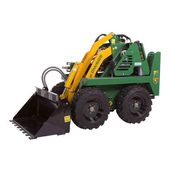
PW628 & DW625
MID RANGE LOADER
OPERATORS MANUAL
WWW.KANGALOADER.COM
1300 4 KANGA
Table of
Contents
Previous
Page
Next
Page
1
2
3
4
5
Advertisement
Table of Contents
Need help?
Do you have a question about the PW628 and is the answer not in the manual?
Ask a question
Questions and answers
Related Manuals for Kanga PW628
Compact Loader Kanga DW625 Operator's Manual
Mid range loader (69 pages)
Compact Loader Kanga 8D Series Operator's Manual
(76 pages)
Compact Loader Kanga 216 Series Operator's Manual
(100 pages)
This manual is also suitable for:
Dw625
Table of Contents
Save PDF
Print
Rename the bookmark
Delete bookmark?
Delete from my manuals?
Login
Sign In
OR
Sign in with Facebook
Sign in with Google
Upload manual
Upload from disk
Upload from URL


Need help?
Do you have a question about the PW628 and is the answer not in the manual?
Questions and answers