Table of Contents
Advertisement
Quick Links
IntelliSpeed
Electronic Speed Control with
ABS Brakes & Reverse
OPERATING INSTRUCTIONS
INTRODUCTION TO INTELLISPEED
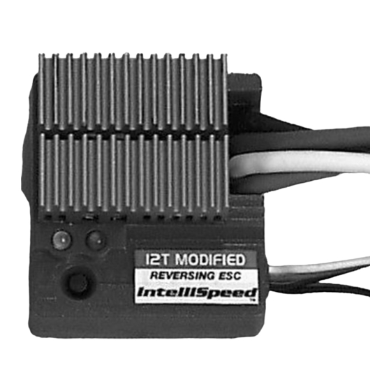
12T MODIFIED ESC
The following instructions will help you get trouble-free operation from your
electronic speed control (ESC). These simple steps will allow your ESC to
achieve maximum performance and minimize the chance of problems due to
incorrect installation. Consult the specifications listed below for limitations for
this ESC. You should always ask your hobby dealer or call our service
department before using the ESC for an application other than what is listed
in these instructions. PLEASE FOLLOW ALL INSTRUCTIONS CAREFULLY!
FEATURES & SPECIFICATIONS
• The IntelliSpeed 12T Modified ESC is designed to be used with any 12-27
turn motors – great for intermediate or competition racing applications.
• Customize the model's traction control with three different built-in
acceleration speed settings.
• Anti-Lock Brake System (ABS) enables greater control while cornering.
• A built-in reverse delay function aids in protecting model gear-trains when
shifting from forward to reverse.
• Reverse lockout meets racing purposes.
• Motor, battery, and radio connectors are pre-installed.
• High frequency operation provides very smooth control, maximizes battery
run time, and reduces operating temperatures.
• High temperature control automatically shuts down the ESC to prevent
damage from occurring during excessive current situations.
Input Power:
Operating Frequency:
BEC:
On-Resistance:
Max. Constant Current:
Max. Peak Current:
Motor Turns Limit:
Acceleration Time Delays:
Case Size (with heat sink):
Weight (with heat sink):
IMPORTANT INSTRUCTIONS
(ESC=ELECTRONIC SPEED CONTROL)
• Do not run the car near water! Never allow water, moisture, or any foreign
material inside the case of the ESC.
• Never use more than 7 cells (8.4 volts total) in the battery pack.
• Do not attempt to connect the battery pack to the ESC in reverse, as
permanent damage to the ESC could result.
• Do not mix instructions. If you are building a vehicle that has a mechanical
speed control, do not use the wiring diagram included with the vehicle.
• Never cut or splice the ESC input wires. Do not connect a battery to the
receiver's (Rx) "battery" slot. The Rx receives power through the ESC itself
which plugs into the Rx's throttle channel slot.
• Three 0.1µF, 50V monolithic capacitors (included) should be properly
installed on any motor that does not have capacitors built-in to reduce
interference from electronic noise. (See step 2).
• Always disconnect the battery pack from the ESC when not in use.
• Never turn on the ESC before plugging it into the Rx and switching on the
transmitter (Tx).
• Be careful not to touch the heat sink during use as it can become very hot.
• For the best performance, use an FM radio system.
STEP 1: MOUNTING THE ESC & RECEIVER
The following information can help the ESC perform at maximum efficiency
and minimize the chance of overheating and radio interference problems.
MOUNTING THE ESC (Figure 1)
1. Locate the ESC in a position to allow for good airflow, with as little
obstruction from the model's outer body or exterior dirt and debris as
possible. Maintaining a clean ESC and achieving good airflow through the
™
™
12T Modified
7.2 to 8.4 volts DC (6-7 cells)
1.0 kHz
5.0 volts / 1.0 amp
0.0035 ohms
232 amps
800 amps
no fewer than 12 turns
0.0, 0.1, and 0.2 seconds
1.48 x 1.34 x 0.57" (42 x 38 x 16mm)
2.44 oz (69g)
heat sink fins is very important for keeping the ESC cool and maximizing
performance.
2. Mount the ESC using double-sided mounting tape.
3. Mount the ON/OFF switch in a convenient place. Ensure that it is securely
mounted, using mounting tape or screws in a location where it cannot be
easily turned off by objects on the track or rough terrain.
MOUNTING THE RECEIVER
1. Radio interference can cause the ESC to rapidly switch between forward and
brake, overheating the transistors and possibly damaging the ESC. The Rx
and its antenna should be mounted as far away from the ESC as possible.
Also, try to keep the Rx away from the motor, battery, power wires, servos,
or any large piece of metal – such as a metal chassis.
2. Make sure the Rx antenna can be fully extended through a mast and not
completely enclosed inside the model. Do NOT cut or coil the Rx antenna.
3. Mounting the Rx deep within the tub of the chassis can greatly increase the
chance for radio interference. Try to mount the Rx away from the bottom of
the chassis tub.
4. Graphite and metal chassis transmit radio noise generated by the motor. To
mount the Rx on a graphite chassis (if necessary), place it on edge with the
crystal and antenna as far away from the chassis as possible to reduce the
chance of radio interference.
Mount
the
speed
control
to
obtain
maximum
parallel
airflow
THROUGH
the heat sink. For
off-road
cars,
or
cars with a metal or
graphite
chassis,
mount the ESC on
the chassis, and the
Rx and antenna on
the rear shock tower
to
reduce
radio
interference.
STEP 2: MOTOR & CAPACITOR CONNECTIONS
Figure 2
Motors generate electrical noise which can interfere with radio reception.
Properly installed capacitors can help reduce the chance of such interference.
Some motors come from the factory with capacitors pre-installed. Check the
motor's instructions to see if capacitors are in place. Otherwise, installation of
the three included 0.1µF 50V non-polarized ceramic capacitors onto the motor
is highly recommended.
• Solder one capacitor between the motor's POSITIVE (+) brush tab and
GROUND tab†.
• Solder one capacitor between the motor's NEGATIVE (-) brush tab and
GROUND tab†.
• Solder one capacitor between the motor's POSITIVE (+) and NEGATIVE (-) tabs.
† Solder to the can of the motor if your motor doesn't have a ground tab.
STEP 3: TRANSMITTER ADJUSTMENTS
Adjusting your transmitter (Tx) is critical for proper speed control operation. The
Tx throttle adjustments are described below:
• ATV, EPA, or ATL - set all to maximum.
• Throttle Trims and Sub Trims – set all at neutral or zero.
STEP 4: RADIO CONNECTOR POLARITIES
By simply clipping off the tab on the side of the connector using wire cutters,
it can be directly connected to any Futaba
receiver. For proper connection refer to your radio's manual. WARNING: This
connector is NOT directly compatible with the old Airtronics connector style.
For old Airtronics radios, it is highly recommended to use an Airtronics Servo
Adapter to connect this ESC to the older style Airtronics radios. NEVER
ALLOW THE RED (+) AND BLACK (-) WIRES TO CROSS ON ANY RECEIVER
OR ESC AS PERMANENT DAMAGE WILL RESULT TO BOTH ITEMS.
Figure 1
Clip tab
®
J, Airtronics "Z," Hitec "S," or JR
Advertisement
Table of Contents

Related Manuals for Duratrax IntelliSpeed 12T


Summary of Contents for Duratrax IntelliSpeed 12T
- Page 1 PLEASE FOLLOW ALL INSTRUCTIONS CAREFULLY! FEATURES & SPECIFICATIONS STEP 2: MOTOR & CAPACITOR CONNECTIONS • The IntelliSpeed 12T Modified ESC is designed to be used with any 12-27 Figure 2 turn motors – great for intermediate or competition racing applications.
- Page 2 U.S. AND CANADA ONLY DuraTrax warrants this product to be free from defects in materials and workmanship for a period of 120 days from the date of purchase. During that period, we will repair or replace, at our option, any product that does Follow these steps to set reverse delay or reverse lockout: not meet these standards.
Need help?
Do you have a question about the IntelliSpeed 12T and is the answer not in the manual?
Questions and answers