Table of Contents
Advertisement
Quick Links
OM-CWF-50A-01-2015
2-5-V
OPERATION MANUAL
CWF-50A
Cold Wire Feeder
February 2015
IMPORTANT
Read this manual carefully before installing,
Commissioning, or operating this product.
Jetline Engineering, 15 Goodyear Street, Irvine, CA 92618
Telephone: (949) 951-1515 Fax: (949) 951-9237
Web site:
www.jetline.com
E-mail:
sales@jetline.com
Advertisement
Table of Contents

Summary of Contents for Jetline CWF-50A
- Page 1 2-5-V OPERATION MANUAL CWF-50A Cold Wire Feeder February 2015 IMPORTANT Read this manual carefully before installing, Commissioning, or operating this product. Jetline Engineering, 15 Goodyear Street, Irvine, CA 92618 Telephone: (949) 951-1515 Fax: (949) 951-9237 Web site: www.jetline.com E-mail: sales@jetline.com...
- Page 3 Jetline's inspection confirms the existence of such defects. Jetline's option of repair or replacement will be F.O.B. factory at Irvine, California, and therefore no compensation for transportation costs of any kind will be allowed.
- Page 4 NOTICE The installation, operation and maintenance guidelines set out in this manual will enable you to maintain the equipment in peak condition and achieve maximum efficiency with your welding operation. Please read these instructions carefully to become aware of every advantage. CAUTION Only experienced personnel familiar with the operation and safe practice of welding...
-
Page 5: Table Of Contents
Table of Contents Section I ............................1 Safety Precautions ......................... 1 Arc Welding ........................1 Electric Shock ........................1 Arc Rays ..........................1 Fumes and Gases ......................2 Cylinders ..........................2 Welding ..........................2 Moving Parts ........................3 EMF Information ....................... 3 Principal Safety Standards .................... -
Page 6: Section I
Section I Safety Precautions Arc Welding Arc Welding can be hazardous. Protect Frequently inspect input power cord for yourself and others from possible serious damage or bare wiring. Replace cord injury or death. Keep children away. immediately if damaged - bare wiring can kill. Pacemaker wearers keep away until Turn off all equipment when not in use. -
Page 7: Fumes And Gases
foot protection where necessary. Never weld on a pressurized cylinder - explosion will result. Fumes and Gases Use only correct shielding gas cylinders, regulators, hoses and fittings designed for the Fumes and gases can be hazardous to your health. specific application; maintain them and Welding produces fumes and gases. -
Page 8: Moving Parts
Moving Parts About Pacemakers: The above procedures are among those also normally Moving parts, such as fans, rotors, and belts can cut recommended for pacemaker wearers. Consult your fingers and hands and catch loose clothing. doctor for complete information. Keep all doors, panels, covers, and guards Principal Safety Standards closed and securely in place. -
Page 9: Section Ii Introduction
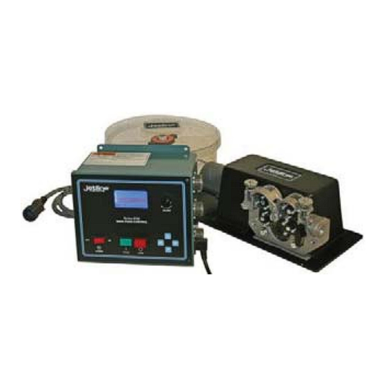
Section II Introduction The cold wire feeder is designed to supply filler metal to the weld puddle in a mechanized tungsten arc welding or plasma arc welding application. The system will accurately feed 0.020”, 0.030”, 0.035”, 0.045”, 0.062” and 0.093” (0.5 to 2.4 mm) hard and soft wires for mechanized TIG or plasma welding. - Page 10 Figure 1 CWF-50 Cold Wire Feeder Set up of Components...
-
Page 11: Section Iii Installation
Section III Installation As standard, the unit is provided with 6 ft. (1830 mm) of cable between the control and the wire drive assembly. The control is typically mounted near the feeder due to the length of the control cable. To mount the wire drive assembly, transfer mounting holes from the wire feeder’s aluminum mounting plate to the mounting surface. - Page 12 At this point, slide the conduit through the outlet guide. You should extend the conduit beyond the tapered end of the outlet guide approximately 1/4” (6 mm). Tighten the set screw securely, holding the conduit properly in position. e. Insert the outlet guide/conduit assembly into the drive roll assembly. Position it so the chamfered conduit is very close to the drive rolls.
- Page 13 Figure 2 Mounting Plate Dimensions...
-
Page 14: Section Iv Wire Feed Accessory Kits
Section IV Wire Feed Accessory Kits Wire Size *Complete Conduit - 6 Outlet Inlet Guide Wire Guide Feed Rolls **Curved Accessory ft (2 m) Guide & Inlet Wire Guide Guide 0.020” 20B6020K 42-23 OG-020 056192 WGT-020 053693 (0.5 mm) PT-40- 0.030”... -
Page 15: Section V Operating Instructions
Section V Operating Instructions Preparation for Welding Mount the spool of welding wire on the spool adapter so the wire will be pulled from the low side of the coil. Adjust the friction brake on the wire spool by adjusting the screw in the center of the spool. -
Page 16: Wire Guide Positioner
When the remote start signal quits, the unit will go through the stop delay, then stop. The unit then proceeds to enter the wire retract time, pulling the wire out of the weld zone. This action prevents the wire from sticking in the weld puddle at the end of the weld. Note: If the retract time is set too long, the wire could retract up into the wire tip. -
Page 17: Section Vi Maintenance
Section VI Maintenance Periodically clean the drive rolls of dirt and chips. Occasionally check the wear of liners, tips, and guides. Periodically check, and replace if necessary, the carbon brushes on the motor. Failure to replace worn brushes could cause severe damage to motor control. Maintenance and electrical work must be performed by experienced and trained personnel. -
Page 18: Section Vii Optional Accessories
Jetline is pleased to offer these enhancements which can be added to your system in the field. If you are interested in these features, please do not hesitate to contact Jetline directly or the nearest distributor for more information. -
Page 19: Section Viii Parts Lists
Section VIII Parts Lists The following pages provide a detailed parts list of all the elements of the cold wire feed unit. Item numbers shown in the parts list refer to those numbers contained in the balloons in the drawing. On each parts list, the quantities shown are the number of items used in that particular assembly. - Page 20 -15-...
- Page 21 CWF-50-DA Cold Wire Feeder Assembly Recommended Item Part Level Level Description CWF-20B-100 Mounting Plate ............1 CWF-20B-110 Mounting Bracket ............1 CWF-20B-120 Cover Assembly ............1 Drive Housing, includes: .........1 046779 Housing ..............1 053842 Gear ................4 10-32x7/8 Flat Head Screw .............12 1/2-20x1 1/4 Hex Head Screw ............4 0467__ Gear Driven Roll Kit ..........1...
- Page 22 -17-...
- Page 23 WGP-1 (Rev L) Wire Guide Positioner Recommended Item Part Level Level Description WGP-1-230 Base ................1 WGP-1-100 (REV E) Cam Plate ..............1 WGP-1-200 Housing ..............1 WGP-1-210 (REV E) Bar ................1 WGP-1-220 Clamp ...............1 WGP-XXX Shown for Reference (part of Wire Feed Kit) WGP-1-240 Stud ................2 WGP-1-250...
- Page 24 -19-...
- Page 25 WGP-2ES (Rev E) Motorized Wire Guide Positioner Recommended Item Part Level Level Description WGP-1 Basic Wire Guide Assembly ........1 WGP-2-5 (REV C) Motor Bracket, detail ..........1 WGP-2-6 Screw................1 WGP-2-7 Motor Bracket, detail ..........1 WGP-2-10 Driven Pulley, detail ..........1 1375K34 Driven Pulley, detail ..........2 WGP-2-10 Driven Pulley ............1 1679K86...
- Page 26 -21-...
- Page 27 WGP-3 Compact Wire Guide Positioner Recommended Item Part Level Level Description WGP-3-2 Base Detail ...............1 WGP-3-3 Yoke Detail ..............1 WGP-3-4 Slide Detail...............1 WGP-3-5 Rotor Detail ..............1 WGP-1-250 V-Block Detail ............2 WGP-1-240 Stud ................2 WGP-3-8 Pin Detail ..............1 WGP-3-9 Clamp Detail ............1 WGP-3-10 Tube Detail...............1 WGP-3-11...
Need help?
Do you have a question about the CWF-50A and is the answer not in the manual?
Questions and answers