
Related Manuals for CENTENT CN0162

Summary of Contents for CENTENT CN0162
- Page 1 OPERATING MANUAL CN0162 MICROSTEP DRIVE 3879 SOUTH MAIN STREE T 714-979-6491 SANTA ANA, CALIFORNIA 92707-5710 U.S.A.
- Page 2 This manual contains information for installing and operating the following Centent Company products: • CN0162 Microstep Drive Centent and the Centent Company logo are trademarks of Centent Company. Other trademarks, tradenames, and service marks owned or registered by any other company and used in this manual are the property of their respective companies.
-
Page 3: Table Of Contents
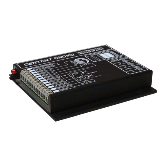
CONTENTS INTRODUCTION GENERAL DESCRIPTION..............3 LOCATION OF COMPONENTS ............4 INSTALLATION POWER SUPPLY ................. 5 PHASE OUTPUTS ................7 MOTOR LEAD COLOR CODE TABLES .......... 10 STANDBY SET ................... 12 DIRECTION ..................13 STEP PULSE..................13 +5 VDC....................14 CURRENT SET .................. 15 CURRENT SET TABLE.............. - Page 4 CENTENT CN0162 MICROSTEP DRIVE 4.0” 101.6mm 0.7” 17.8mm 4.5” 114.3mm 3.625” 92.1mm 0.20” 5.1mm 0.186” 3.25” 4.7mm 82.6mm 1 2 3 4 5 6 7 8 9 10 11 12 0.85” 0.125” 21.5mm 3.2mm 3.625” 92.1mm Figure 1: CN0162 MICROSTEP DRIVE...
-
Page 5: General Description
Over-current (winding shorts etc.), over-temperature (insufficient heat sinking), and under-voltage are automatically sensed by the CN0162. When any of these conditions occur the CN0162 shuts down and turns on a 'fault' LED to indicate the presence of the fault condition. -
Page 6: Location Of Components
LED. OFFSET TRIMPOTS These two adjustment pots allow the user to trim the CN0162 to a particular step motor. This nulls out any residual step error and is especially effective at microstep resolutions of 16 or above. -
Page 7: Installation
INSTALLATION INSTALLATION When operating the CN0162 at high power levels an external heatsink must be attached to the mounting plate. Optional heatsink kits in various configurations are available from Centent Company. No terminals or connectors are required on the wiring to the drive. A wire size of 16-22 gauge is recommended. - Page 8 ) placed in series with Terminal 2 and the power supply. Be sure this fuse is located between the power supply and the zener diode. In the event of an over-voltage condition the zener diode and fuse may be destroyed, but the CN0162 and power supply will be protected from damage.
-
Page 9: Phase Outputs
CN0162 (see page 23 - Power-On Reset). The CN0162 will drive 4, 6 and 8 wire motors. With 6 wire and 8 wire motors, the user has the option of connecting the windings in a high or low performance configuration. - Page 10 Table I & Table II (Page 10) show various manufacturer's 6 wire motor lead color codes and how they connect to the CN0162 for full winding and half winding operation. Table III & Table IV (Page 11) show various manufacturer's 8 wire motor lead color codes and how they connect to the CN0162 for series and parallel wired operation.
- Page 11 INSTALLATION The CN0162 is a high frequency switching type drive. Because of the rapid rate of voltage and current change inherent with this type of drive, considerable RFI is generated. The following precautions should be taken to prevent noise from coupling back to the inputs and causing erratic operation.
-
Page 12: Motor Lead Color Code Tables
Table I: FULL WINDING OPERATION MOTOR TERMINAL MANUFACTURER SUPERIOR ELECTRIC GRN/WHT GREEN RED/WHT RAPIDSYN GRN/WHT GREEN RED/WHT GRN/WHT GREEN RED/WHT EASTERN AIR DEV. GRN/WHT GREEN RED/WHT PACIFIC SCIENTIFIC BLACK ORANGE YELLOW WARNER ELECTRIC BROWN ORANGE YELLOW VEXTA BLUE BLACK GREEN JAPAN SERVO BLUE YELLOW... - Page 13 Table III: SERIES WINDING OPERATION MOTOR TERMINAL MANUFACTURER SUPERIOR ELECTRIC RED/WHT GREEN GRN/WHT (BLACK-WHITE) (ORANGE-BLK/WHT) PACIFIC SCIENTIFIC BLACK ORANGE YELLOW (BLK/WHT-ORG/WHT) (RED/WHT-YEL/WHT) BODINE BROWN ORANGE YELLOW (BRN/WHT-ORG/WHT) (RED/WHT-YEL/WHT) PORTESCAP BROWN ORG/WHT YEL/WHT (BRN/WHT-ORANGE) (RED/WHT-YELLOW) DIGITAL MOTOR BLACK ORANGE YELLOW (BLK/WHT-ORG/WHT) (RED/WHT-YEL/WHT) Table IV: PARALLEL WINDING OPERATION MOTOR TERMINAL...
-
Page 14: Standby Set
STANDBY SET TERMINAL 7 This output implements the automatic standby feature of the CN0162. By reducing the phase current to a lower, 'standby' level the drive system operates cooler during periods of motor inactivity. Heating of the motor, drive, and power supply are kept to a minimum by utilizing this option. -
Page 15: Direction
STEP PULSE TERMINAL 9 Microstepping in the CN0162 occurs on both edges of the step pulse input. This is done to improve motor smoothness at low speeds. The current is changed in the PHASE A-B motor winding on the leading edge of the step pulse. -
Page 16: Vdc
CENTENT CN0162 MICROSTEP DRIVE The CN0162 employs an optocoupler to isolate the STEP PULSE input from the driver's power supply. The user must provide a +5 VDC supply to operate the optocoupler circuitry. This permits the use of current sink drivers, such as TTL logic or open collector transistors, to operate the input. -
Page 17: Current Set
(Terminal 11 voltage equals 2.5 volts), Zero phase current occurs with CURRENT SET shorted to ground (Terminal 11 voltage equals 0 VDC). THE CN0162 DEFAULTS TO ITS MAXIMUM CURRENT OF 7.2 AMPS PER PHASE IF NO CURRENT SET RESISTOR IS PRESENT. THIS MAY CAUSE DAMAGE TO A MOTOR THAT IS TOO SMALL FOR THIS CURRENT LEVEL. -
Page 18: Current Set Table
CENTENT CN0162 MICROSTEP DRIVE CURRENT SET TABLE MODE OF OPERATION RESISTOR HALF WINDING FULL WINDING STANDARD ±5% (PARALLEL) (SERIES) (OHMS) 0.1 A 0.2 A 0.2 A 0.4 A 1.3 K 0.3 A 0.6 A 2.0 K 0.4 A 0.8 A 2.7 K... -
Page 19: Resolution Select
Jumpers are installed as shown in Figure 7. MICROSTEPS PER STEP SEL. A: The resolution for each selection is printed on the SEL. B: case of the CN0162. To select a microstep SEL. C: SEL. D: resolution, install jumpers in the following manner: SEL. -
Page 20: Resolution Options Table
CENTENT CN0162 MICROSTEP DRIVE Twenty-one different microstep resolutions are available in the CN0162. The drive is supplied to the user with 4 of the 21 O P T I O N available. Not all combinations of step resolutions are possible. Table VI may be... -
Page 21: Microstep Compensation (Offset Trimpot Adjust)
The left trimpot compensates the PHASE A-B outputs while the right trimpot compensates the PHASE C-D outputs. There are two methods for trimming the CN0162 to a motor and power supply. Both methods require the motor and power supply to be connected to the CN0162. -
Page 22: Microstepping
A 200 step per revolution motor, operated at 100 microstep resolution, will take 20,000 microsteps to complete one revolution of the motor shaft. The twenty-one different resolutions available in a CN0162 are represented in Table VI as the column designated STEP RESOLUTION. -
Page 23: Anti-Resonance
The CN0162 incorporates a mid-band anti-resonance compensation circuit that closes the loop on this instability and electronically damps it out. Since the motor is now... - Page 24 CENTENT CN0162 MICROSTEP DRIVE SU P ERI OR M0 62 - FD 0 4 150Hz RA PI DS YN 3 4 D - 920 8A 100Hz 50Hz SI GM A 20 - 2 235 0- 2 8 17 5 5K Hz 1 0 K H z 1 .
-
Page 25: Power-On Reset
When the power supply voltage falls below 5 volts, the Phase outputs go open circuit and float. While the CN0162 is in an under-voltage condition, the drive is held in the reset state. Once the power supply voltage rises above 11.75 volts and all internal voltages have... -
Page 26: Fault Led
70°C. The drive will not operate after it has cooled down. The power supply must be 'recycled' to operate the drive. If a CN0162 has shut down due to overheating, the cause is usually an inadequate heatsink. Do not continue to operate the drive until adequate heat sinking has been provided. -
Page 27: Chopping Frequency
FEATURES If a CN0162 has shut down due to an over-current condition, determine the cause and correct it before recycling the power supply, otherwise it will simply shut down again. Overheating shutdowns can be distinguished from over-current shutdowns by observing the case temperature of the CN0162. - Page 28 The microstep resolutions for compensated profiles are the same as those available for the standard sine-cosine version of the drive. It is also possible to order a CN0162 with different current profiles at the same microstep resolution. The option header would then choose between motor types rather than resolutions.
-
Page 29: Performance
By varying the value of the current set resistor, it may be possible to trim out residual positional error. Should this be inadequate, Centent can generate a compensation profile for motors of a like -1.8° +1.8°... -
Page 30: Motor Load
CENTENT CN0162 MICROSTEP DRIVE MOTOR LOAD Generally speaking, motor load is the single most significant contributor to microstep positioning error. A step motor only generates torque when a rotor error angle exists. The relationship between rotor displacement angle and restoring torque for a typical motor is shown in Figure 10. - Page 31 PERFORMANCE In Region 1 motor torque is nearly proportional to motor current. Torque remains constant until it intersects the motor's load line, which may be approximated with the equation: where: T = torque k = motor constant V = power supply voltage f = steps per second L = motor inductance REGION 1...
-
Page 32: Motor Winding Configuration
The intersection of this slope and the speed axis determines the maximum speed of the motor. THE CENTENT CN0162 DRIVE IS CAPABLE OF RUNNING STEP MOTORS AT SPEEDS HIGH ENOUGH TO CAUSE DAMAGE TO MOTOR SHAFT BEARINGS. - Page 33 Region 2 if the power available is sufficient. The benefits are low motor and drive heating and modest power supply current requirements. For full-winding operation the phase current level of the CN0162 is set to one-half the motor's nameplate phase current rating.
- Page 34 CENTENT CN0162 MICROSTEP DRIVE ( 6 A /P H A SE ) ( 5A /PH ASE) T O R Q U E ( 4A /P H A S E) ( O Z / I N ) ( 3A /P H A S E)
-
Page 35: Power Supply Voltage
Consequently maximum motor shaft power is also proportional to the power supply voltage. The CN0162 step motor drive has a power supply range from 12 to 80 VDC. This results in a motor power range of 6.6:1. Increasing power supply voltage increases motor heating. Taking this into consideration, the choice of power supply voltage should be just high enough to meet the application's power requirements and no higher. -
Page 36: Motor And Drive Heating
CENTENT CN0162 MICROSTEP DRIVE 1.5A 1.0A 0.5A FULL STEPS PER SECOND Figure 14: Power supply current MOTOR AND DRIVE HEATING Motor and drive heating is equivalent to the difference between the electrical power input and the motor's mechanical power output. The ratio of output power to input power is the system efficiency. - Page 37 CN0162 drive. Generally, if the CN0162 is too hot to touch, additional cooling is required. The case temperature of the drive should never under any circumstance be allowed to exceed +70 degrees C (+158 degrees F).
-
Page 38: Specifications
SPECIFICATIONS ELECTRICAL GENERAL UNITS Resolution µStep Supply voltage Current (no motor) PWM frequency Motor inductance Motor phase current STEP PULSE INPUT Logic '1' voltage Logic '0' current Pulse width 'high' nSec Pulse width 'low' nSec Rise time Fall time Frequency DIRECTION INPUT Logic '1' voltage Logic '0' current... - Page 39 Centent Company manufactures a complete line of step motor products. In addition to the CN0162 high resolution microstep drive, the following drives are designed to serve a wide variety of motors and applications. They all share the compact, rugged design characteristics of the CN0162.