
Summary of Contents for Kingsley KIP-20
- Page 1 KIP-20 OPERATION AND MAINTENANCE MANUAL WIRE MARKING MACHINE Kingsley, ITW Marking and Coding 5307 Meadowland Parkway Marion, Illinois 62959 Phone (866) 421-9898 Fax (618) 997-1766...
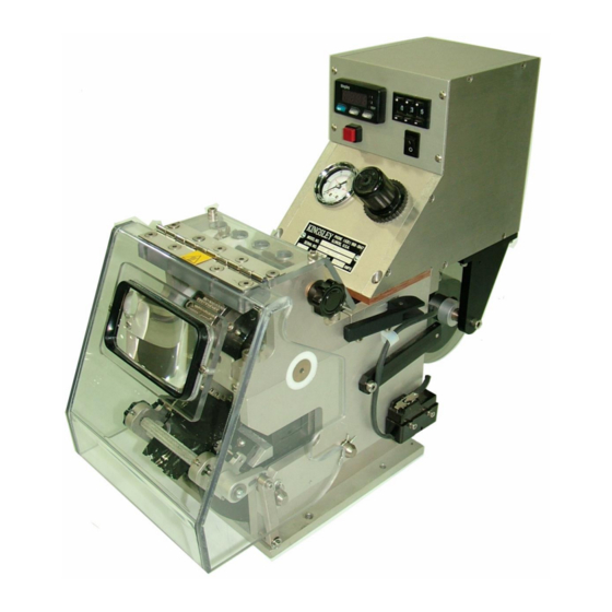
- Page 2 INTRODUCTIOIN GENERAL The KIP-20 as shown in Figure 1 is a remote-operation wire-marking machine. It is designed to work as a SLAVE unit in an assembly process and mark on command from a host signal. The machine provides permanent marking of alpha/numeric characters in vertical and horizontal formats on insulated wire.
- Page 3 SCOPE OF MANUAL This manual provides instructions for the installation, operation, periodic maintenance, and troubleshooting of the KIP-20 Wire Marking Machine. It is intended to be used by operators and plant maintenance personnel. A list of recommended spare parts in located at the back of the manual. In order to minimize downtime, Kingsley recommends that the suggested quantity of each part to be kept on hand for each marking machine in service.
- Page 4 Use the following procedure to connect the controller to the host machine. Figure 2 is the wiring diagram of the KIP-20. The 4-conductor connector provides the means for the host machine to control the wire-marking machine.
- Page 5 An incorrectly wired interconnect cable can cause damage to the wire marking machine. If you are not sure how to wire the interconnect cable, call Kingsley before connecting the KIP-20. Ensure that the mating male connector is properly wired and connected to the host machine and insert the connector into the female mounted on the side of the control box on the KIP-20.
- Page 6 The KIP-20 requires 4 Amp. 115 VAC (3 Amp 230 VAC optional) of available incoming power. Ensure that the available power is sufficient for the system and that electrical equipment and installation meets all national and local codes.
- Page 7 Appendix A lists foils available from Kingsley, their typical application, and approximate machine settings for that foil. The roll of foil mounts on the foil spool shaft at the back of the machine. Use the following procedure to install a roll of foil.
- Page 8 Figure 4 Loading Foil into Feed Mechanism SELECT AND INSTALLING THE WIRE FIXTURE Kingsley offers a complete range of wire holding fixture sizes (refer to Appendix B). Figure 5 illustrates the wire fixtures and calls out the important elements: Wire Guide and Wire Groove.
- Page 9 Figure 5 Wire Fixture SETTING THE LEGEND If Typewheel were ordered with the KIP-20, they were mounted at the factory, and the unit is ready to operate. If Typewheel were ordered separately, they must be installed before the KIP-20 is ready to operate.
- Page 10 Figure 6 Typewheel Lock Bar 2. Refer to Figure 7, and slide the selector bar until the position indicator aligns with the typewheel you wish to adjust. 3. Use the sight glass to view the markings on the typewheel. The character visible beneath the imprint tooth indicates the character that will be marked on the wire.
- Page 11 Figure 7 Setting the Typewheel POWER UP After all components are installed, the system is ready to start. Use the following procedure to start the system and check the installation. 1. Ensure that the air supply is on. 2. Place the ON/OFF switch in ON position. The power indicator lights and the temperature controller displays the current heater temperature.
- Page 12 Temperature controller is set for the unit of measure normally used in your location, F or C. Kingsley recommends not changing the unit of measure. If you need to make this change, please contact Kingsley before attempting to do so.
- Page 13 Use the following procedure to set the air pressure. 1. Locate the adjusting knob on the air pressure regulator. 2. Gently pull up on the knob to unlock it. 3. Turn the knob clockwise to increase the pressure or counterclockwise to decrease the pressure.
- Page 14 OPERATION THEORY OF OPERATION The KIP-20 Wire Marking Machine works in conjunction with a host machine to imprint legends on wire insulation. The host machine sends the signal to the KIP-20 to synchronize the imprinting with the position of the wire.
- Page 15 Figure 8 Print Cycle Time START UP Place the ON/OFF switch in the ON position to start the KIP-20. The temperature controller supply the power to heating element to heats the typewheel, and when the typewheel reach normal operation temperature, the machine is ready to operate.
- Page 16 MAINTENANCE GENERAL This section provides instructions for periodic maintenance and adjustment of the KIP-20 Wire Marking Machine. The system requires a minimum amount of maintenance and does not require lubrication. Keep the machine dry and clean. If the machine is wet, it presents a shock hazard.
- Page 17 DAILY Check the Filter/Regulator for buildup of dirt or water. If the filter is excessively dirty, air pressure will drop and the imprint quality will suffer. Drain Moisture/Water as required. If the filter becomes clogged have plant maintenance clean or replace filter. CLEANING Type Buildup of dirt or other foreign matter on the type will affect the quality of the imprints.
- Page 18 3/32 inch (0.80 mm to 1.60 mm). ALIGNMENT The KIP-20 is aligned at the factory before shipment. The machine can become miss- aligned if not handled with care. If the machine is miss-aligned axially, the wire fixture is not square to the typewheel and the legend does not imprint evenly. If the machine miss-...
- Page 19 Figure 10 Axial Alignment 3. Allow the machine to cool to ambient temperature. 4. Remove the wire fixture and install the Kingsley alignment fixture (Part No. 10172). Tighten the two setscrews. 5. Refer to Figure 10 and loosen the two securing screws approximately ¼...
- Page 20 Process to the radial alignment procedure Radial Alignment NOTE: Ensure that the axial alignment is set before performing the radically alignment procedure. Temperature within the unit can approach 600 F (316 C). Contact with high-temperature surfaces can cause serious burns. Avoid contact with all hot components in the Wire Marking Machine.
- Page 21 INSTALLING TYPEWHEELS Kingsley offers a variety of typewheels to meet most imprinting requirements. Appendix C lists the available typewheels. Use the following procedure to change or add a typewheel. Temperature within the unit can approach 600F (316C). Contact with high-temperature surfaces can cause serious burns.
- Page 22 18. If the typewheels are not centered to the mandrel, loosen the left spacer and slide the typewheels and spacers to the approximate center. Secure the left spacer by tightening the setscrew until it is snug. NOTE: The typewheels must be free to turn when they are assembled to the mandrel.
- Page 23 Use the Troubleshooting Chart as a guide to determine the possible cause and ultimate remedy for a symptom the machine is exhibiting. If you encounter a problem not covered in this manual, or if the corrective action fails to eliminate the symptom, call Kingsley for assistance. TROUBLESHOOTING CHART...
- Page 24 KIP-20 RECOMMENDED SPARE PARTS PART No. DESCRIPTION SUGGESTED Qty. 43013-A Air Filter Regulator E-1201 Microswitch, Foil Out E-1322 Typewheel Mandrel Insulator Ring - Large E-1323 Typewheel Mandrel Insulator Ring - Small MPWE-730-40 Thermocouple E-727-425 Heating Element, 120 V E-727-425220 Heating Element, 220 V (220 V Machine only)
- Page 25 The following pages contain exploded views and associated parts list for the KIP-20 Wire Marking Machine. Use these illustrations and parts lists to identify parts you wish to order. Locate the parts on the illustration and note its Index Number. Find the part in the parts list and order the part by...
- Page 26 Figure 14 KIP-20 Lower Assembly Exploded View...
- Page 27 KIP-20 LOWER ASSEMBLY (Figure 14) Index Part Number Description Qty. SHC1032X5/8 Socket Head Cap Screw E-1285A Bottom Plate AW-1410-6B Pin for Linkage Arm E-1286A Lower Side Plate E-1280B Busing E-1524-410 Air Valve SHC632x1 Socket Head Cap Screw 6-32 x 1”...
- Page 28 Figure 15 KIP-20 Upper Assembly...
- Page 29 KIP-20 Upper Assembly Figure15 Index Part Number Description Qty. E-1196 Knob Black Plastic E-1163 Lock Pin E-1280B Bushing E-1289A Side Plate Upper Left (Bottom) E-1322 Insulator, Ring Large E-1291S Mandrel with Slot E-1324-750 Spacer ¾” VARIES Typewheel Varies E-1324-11 Spacer...
- Page 30 Figure 16 KIP-20 Foil Feed Assembly...
- Page 31 KIP-20 Foil Feed Assembly (Figure 16) PART NUMBER AW-1410-X Index Part Number Description Qty. P001 Foil Feed Right Side Plate P002 Foil Feed Left Side Plate P003 Roller Clutch Housing P004 Foil Feed Bottom Shaft P005 Oilite Bushing AW-1457-11 Drive Knob...
- Page 32 Figure 17 KIP-20 Typewheel Clamp Assembly Exploded View...
- Page 33 KIP-20 TypeWheel Clamp Assembly (Figure 17) Index Part Number Description Qty. E-1090 Pic Screw #4428 E-1309 Crank Type Lock E-1301 Bar Cam Lock E-1301-1 Type Lock Bar E-1303 Spacer Block E-1302 Plate Lock Cam SHC1032X7/8 Socket Head Cap Screw 10-32 x 7/8...
- Page 34 Figure 18 KIP-20 Typewheel Index Assembly...
- Page 35 KIP-20 Typewheel Index Assembly (Figure 18) Index Part Number Description Qty. P006 Upper Left cap P008 Slide Block Guide Rod P009 Index Carrier BHCS632X1/4 Button Head Cap Screw P013 Window Frame P012 Insulated Knob P010 Tube Selector Shaft E-1157 Bronze Bushing...
- Page 36 Figure 19 KIP-20 Control Box Assembly Exploded View...
- Page 37 KIP-20 Control Box Assembly (Figure 19) Index Part Number Description Qty. E-761A Ring for Regulator E-761 Air Pressure Regulator EC1002 Switch On / Off MCM-1706 Swivel Elbow 1/8 NPT x 1/4 P021 3 Digit Potentiometer P016 Control Box Bottom Plate...
- Page 38 (temperature, pressure and dwell) to the Kingsley Lab. Be sure to include an unmarked sample for the lab to use. As a no-charge service, Kingsley will mark and return samples of your products with complete recommendations for foil, marking temperature, dwell, pressure, holding fixture, and the type that was used.
- Page 39 FOIL RECOMMENDATIONS Material to be marked First Choice Alternate Acrylics (Plexiglas) K-30 Anodized Aluminum Foil Labels No Fault Celluloid K-30 Cross-linked Neoprene No Fault Cross-linked Polyethylene (XL-PE) No Fault Cross-linked Polyolefin No Fault Cross-linked Polyvinyl Chloride (XL-PVC) No Fault K-520 Ethylene Tetrefluoroethelence K-520 (TEFZELETFE)
- Page 40 FOIL CROSS-REFERENCE CHART FOIL RECOMENDED APPLICATION TEMP. DWELL K-30* Thermoplastic materials, including: Acrylics (PLEXIGLAS) Celluloid Quick 375-425 F Polyethylene Polyamides (NYLONS) Polyvinyl Chloride (PVC) No Fault Anodized Aluminum Foil Labels Crosslinked Neoprene Crosslinked Polyolefin Crosslinked Polyethylene (XLPE) Quick 300-375 F Crosslinked Polyvinyl Chloride (KYNAR XLPVF) Polyethylene Polyvinylidene Fluoride (KYNAR)
- Page 41 APPENDIX B – KINGSLEY WIRE FIXTURES WIRE FIXTURES – WFC Fixtures are designed to provide both a single marking area for continuous incremental marking, and side by side marking areas for simultaneous end marking applications. Fixture size is determined by taking a loose micrometer reading of wire outside diameter.
- Page 42 The proper sizing of these items is critical to achieving maximum efficiency of the printer with minimum of insulation penetration. All Kingsley typewheels have forty characters (letter A – Z, Numbers 0 – 9 and special characters: Left arrow, Hyphen, and Blank). Typewheel machines mark one line of type.
Need help?
Do you have a question about the KIP-20 and is the answer not in the manual?
Questions and answers
How do you tighten the letters? The lock bar is not locking letters when pushed closed.
The Kingsley KIP-20 uses typewheels to mark characters, and these are secured by a lock bar. If the lock bar is not locking the letters properly, check the following:
1. Ensure the lock bar is fully engaged and tightened.
2. Verify that the typewheels are correctly seated in their slots.
3. Inspect the lock bar for any debris or misalignment preventing it from securing the typewheels.
4. If necessary, adjust or replace the lock bar to ensure a firm grip on the typewheels.
If the issue persists, recheck the alignment and seating of the components.
This answer is automatically generated