Sign In
Upload
Download
Table of Contents
Contents
Add to my manuals
Delete from my manuals
Share
URL of this page:
HTML Link:
Bookmark this page
Add
Manual will be automatically added to "My Manuals"
Print this page
×
Bookmark added
×
Added to my manuals
Manuals
Brands
Vent-Axia Manuals
Control Systems
Sentinel
Installation operation & maintenance
Vent-Axia Sentinel Installation Operation & Maintenance
Totus 2 d-erv
Hide thumbs
Also See for Sentinel
:
User, installation & maintenance manual
(18 pages)
1
2
Table Of Contents
3
4
5
6
7
8
9
10
11
12
13
14
15
16
17
18
19
20
21
22
23
24
25
26
27
28
29
30
31
32
33
34
35
36
37
38
39
40
41
42
43
44
45
46
47
48
49
50
51
52
53
54
55
56
57
58
59
60
61
62
63
64
65
66
67
68
page
of
68
Go
/
68
Contents
Table of Contents
Troubleshooting
Bookmarks
Table of Contents
Table of Contents
Product Description
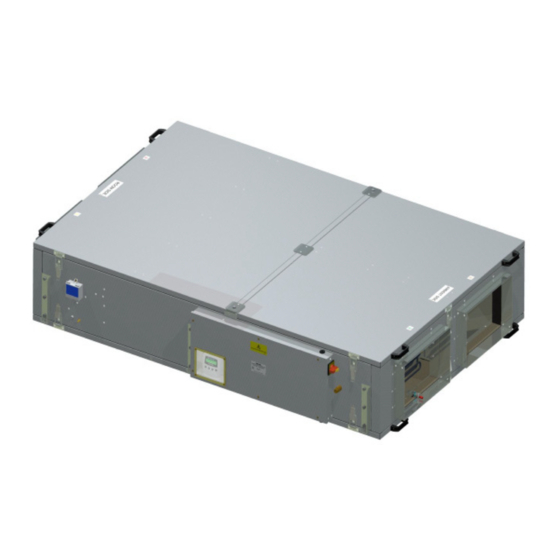
Sentinel Totus 2 D-ERV
Commissioning Record
Sentinel Totus 2 D-ERV Technical Specification
Technical Specification
Dimensions
Installation
Installing Your Energy Recovery Ventilation System
Before Installing Your Equipment
Physical Installation
Electrical Installation
Switching On/Off
Commissioning
Commissioning Your Energy Recovery Ventilation System
Commissioning Screens
The Settings Code
Writing down the Settings Code
Default Settings
Restore Settings Screens
Restoring Settings
About Operation and Monitoring
Operation and Monitoring
Status Monitoring Screens
Maintenance
Cover Removal/Replacement
3 Monthly Maintenance
5 Yearly Maintenance
Caring for Your Unit
Removal/Replacement of Parts
Filter Removal/Replacement (Ceiling-Mounted)
Filter Removal/Replacement (Roof-Mounted)
Motor Removal/Replacement (Roof-Mounted)
Motor Removal/Replacement (Ceiling-Mounted)
Float Switch Removal/Replacement (Roof-Mounted)
Float Switch Removal/Replacement (Ceiling-Mounted)
Condensate Pump Removal/Replacement (Roof-Mounted)
Condensate Pump Removal/Replacement (Ceiling-Mounted)
Filter Removal/Replacement (Maxi)
List of Spares
Diagnosing a Problem
Diagnostic Codes
Troubleshooting
Fault Led/Status Relay
Power Supply Troubleshooting
Airflow/Temperature Troubleshooting
Condensate Troubleshooting
Appendix A: Glossary
Terms and Abbreviations
Appendix B: Options and Accessories
Sentinel Totus
Appendix C: Main Controller PCB Terminals
Terminals
Advertisement
Quick Links
1
Sentinel Totus 2 D-Erv
2
Filter Removal/Replacement (Ceiling-Mounted)
3
Diagnosing a Problem
4
Fault Led/Status Relay
Download this manual
Sentinel
Totus 2 D-ERV
Installation, Operation & Maintenance
PLEASE RETAIN THESE INSTRUCTIONS WITH THE PRODUCT.
Stock Ref. N°
TOTUS2MINI
TOTUS2MINI/CP
TOTUS2MIDI
TOTUS2MIDI/CP
TOTUS2MAXI
TOTUS2MAXI/CP
Copyright © 2009 Vent-Axia Limited. All rights reserved.
Table of
Contents
Previous
Page
Next
Page
1
2
3
4
5
Advertisement
Table of Contents
Troubleshooting
Troubleshooting
58
Fault LED/Status Relay
59
Airflow/Temperature Troubleshooting
60
Condensate Troubleshooting
61
Need help?
Do you have a question about the Sentinel and is the answer not in the manual?
Ask a question
Questions and answers
Related Manuals for Vent-Axia Sentinel
Fan Vent-Axia Sentinel User, Installation & Maintenance Manual
Kinetic mvhr & cooker hood (18 pages)
This manual is also suitable for:
Totus 2 d-erv
Totus2mini
Totus2midi
Totus2mini/cp
Totus2midi/cp
Totus2maxi
...
Show all
Totus2maxi/cp
Table of Contents
Save PDF
Print
Rename the bookmark
Delete bookmark?
Delete from my manuals?
Login
Sign In
OR
Sign in with Facebook
Sign in with Google
Upload manual
Upload from disk
Upload from URL


Need help?
Do you have a question about the Sentinel and is the answer not in the manual?
Questions and answers