
Subscribe to Our Youtube Channel
Summary of Contents for EES USM series
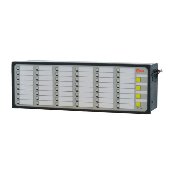
- Page 1 Universal fault annunciator for panel mounting USM – Universal fault annunciator for panel mounting (2nd Generation) Operating manual MSM-USM2G-BA-UK-001...
-
Page 2: Table Of Contents
Table of content Table of content 1 Validity ..............................4 2 General notes ............................5 2.1 Additional instructions ........................5 2.2 Usage ..............................5 2.3 Target group ............................. 5 2.4 Symbol definition ..........................5 2.5 Safety instructions ..........................7 2.5.1 Appropriate use .......................... 7 2.5.2 Storage of the manual ........................ - Page 3 Table of content 5.4 Parameterisation by push buttons ....................41 6 Parameterisation by Excel-file ......................42 6.1 Alarm channels and IEC objects ..................... 42 6.1.1 Alarms ............................42 6.1.2 IEC-objects of the reporting channels ..................43 6.2 Repeat relays and IEC objects ...................... 44 6.2.1 Relays ............................
-
Page 4: Validity
General notes 1 Validity The description covers the USM devices with the following options: Number of reporting inputs 08 Reporting inputs 16 Reporting inputs 24 Reporting inputs 32 Reporting inputs 40 Reporting inputs 48 Reporting inputs Operating voltage 24 V AC/DC 48 - 60 V AC/DC 110 - 220 V AC/DC Signal voltage... -
Page 5: General Notes
General notes 2 General notes 2.1 Additional instructions This manual provides the safe and efficient use with the devices of the universal fault annunciating system (in the following called „USM, fault annunciator or device) The manual is part of the device and must be stored always accessible for the personnel in direct proximity of the device. - Page 6 General notes DANGER! This combination of symbol and signal word warns of a hazardous situation which can lead to death or severe injuries if not avoided. WARNING! This combination of symbol and signal word warns of a possibly hazardous situation which can lead to death or severe injuries if not avoided.
-
Page 7: Safety Instructions
Germany Telephone + 49 (0) 7191/182-0 Telefax +49 (0) 7191/182-200 E-Mail info@ees-online.de Internet www.ees-online.de Further we are looking forward to receiving feedback and experiences which result from the application and are useful for improvement of our products. MSM-USM2G-BA-UK-001 Page 7 of 46... -
Page 8: Copyrights, Trademark Rights, Gnu Licenses
If the consignment on a data medium is required, we will provide this against an additional charge of € 10,-. Please channel you request to our customer support. E-Mail: info@ees-online.de Telefon: + 49 (0) 7191/182-0... -
Page 9: Functional Description
Additional explanations to the integrated alarm sequeces can be found in the separate document „Alarm sequences of EES-Fault annunciators“ (SM-MA-ZI-UK). 3.2 Internal Relays cards (optional) The optionally integrated relay cards (8 NO contacts each) are independent from the 4 function relays of the annunciator and can be assigned the following functions: 1. -
Page 10: Dual Power Supply (Optional)
Functional description 3.3 Dual power supply (optional) Independent from the primary power supply, a second, redundant power supply can be integrated into the fault annunciator. Two different voltage variants are available: 24 – 60 V AC/DC 110 – 220 V AC/DC The voltage level of the redundant power supply can be chosen independently from the voltage level of the primary power supply. -
Page 11: Protocol Interfaces
Functional description ü Possible Not possible Fig. 3.2: Examples of cascaded annunciator systems 3.5 Protocol interfaces For communication to superior or inferior systems (e.g. SCADA or PLC) the USM provides one or two interface cards. These contain the following interfaces: Card 1 (always equipped) Card 2 (optionally equipped) ... -
Page 12: Protocol Iec 61850 (Optional)
Functional description SCADA SCADA SCADA In this application example, the USM annunciators act as acquisition devices which process and display alarms locally. In addition, the alarms are forwarded to the SCADA level through IEC 60870-5-101 or -104. Fig. 3.3: Application example for communication of USM acquisition devices (IEC-Server/Slave) with an IEC-Client/Master. -
Page 13: It Security Functionalities (Optional)
Functional description Fig. 3.4: With the optionally available software license IEC 61850 the USM can be integrated into IEC 61850 structures 3.7 IT security functionalities (optional) For companies in the energy business a whitepaper with fundamental security measures for control and telecommunication systems has been released. -
Page 14: Diagnosis
Functional description - error ( section „Diagnosis“) Flashing red Flashing green - initialisation of the annunciator Terminals power supply Terminals function relays Terminals signal inputs Terminals function inputs LAN-connector (Ethernet / RJ45) Terminal serial interface (RS232 optionally RS 485) Watchdog-LEDs „Communication“ [10] - Tx serial interface green - Rx serial interface... -
Page 15: Error Codes
Internal error If the error still is at issue after restart of the device, the device Internal error needs to be returned to EES for inspection. After a surge of alarms, interstages of alarms can be lost. The Overflow alarm buffer final stages of the alarms are valid. -
Page 16: Operation Modes
Functional description 3.10.3 Operation modes By means of a push button or function input, the annunciator can be set to different operation modes. A currently activated operation mode is indicated by green flashing of the OK-LED with dedicated flashing sequences as follows: Flashing sequence Operation mode Comment... -
Page 17: Terminal Assignments
Functional description 3.11 Terminal assignments Fig. 3.7: Terminal assignment USM MSM-USM2G-BA-UK-001 Page 17 of 46... -
Page 18: Technical Data
Functional description 3.12 Technical data Supply voltage U Rated voltage Voltage range 10…19 V DC or 8…13 V AC 12 V AC/DC 19…37 V DC or 14…26 V AC 24 V AC/DC 37…73 V DC or 26…51 V AC 48 V AC/DC or 60 V DC 100…370 V DC or 85…264 V AC 110 V AC/DC or 220 V AC/DC Table 3.3: Supply voltage keys - USM... - Page 19 Functional description * The power consumption of 32- and 48-way annunciators with integrated repeat relays refers to a maximum number of 2 relay cards (16 relays). General data Buffer time in the event of failure / short circuit 100 ms* adjustable (5 ms …...
- Page 20 Functional description Dielectric strength Electromagnetic compatibility Noise immunity acc. to DIN EN 61000-3-2 / CLASS A DIN EN 61000-3-3 DIN EN 61000-4-2 / 4/8 kV / Criterion A DIN EN 61000-4-3 / Imm. Test Level 3 / Criterion A DIN EN 61000-4-4 / Imm. Test Level 3 / Criterion A DIN EN 61000-4-5 / Imm.
-
Page 21: Mounting And Installation
Mounting and installation 4 Mounting and installation 1. Unpack all modules of the delivery and check for possible transport damages. Report any transport damages to the responsible forwarding agent immediately. Please verify the integrity of the delivery according to the shipping documents. 2. -
Page 22: Parameterisation By Web-Server
Parameterisation 5 Parameterisation by Web-Server The parameterisation of the USM is done through the integrated web-server by means of a web- browser. For access to the web-server, the network interface (terminal X8) of the USM has to be connected to the PC. System requirements ... - Page 23 Parameterisation After login the first page is opened. Fig. 5.2: Start page of the USM Web-server, tab reporting channel Next to the EES logo the menu bar contains the three main menus: Language Parameter Configuration and the symbol bar consisting of five buttons: The buttons have the following functions: ...
-
Page 24: Main Menu Language
Parameterisation In the main window the menu “Parameter / Master-device” is already opened. The parameterisation could be started straight away. In this manual though, the single menus will be explained first in the order of their appearance in the menu bar. Some parameterisation pages are structured by different tabs and contain additional buttons. -
Page 25: Menu Info
Parameterisation Master-device / Slave-device 1..3 (Annunciator functionalities) Reporting channel Reporting sequence Push buttons & function inputs Function relays Repeat relays LED-colour settings Group protocols IEC 61850 IEC 60870-5-101/104 In this manual only the parameterisation settings in the group „System“ are described. For explanation of the settings in the group „Protocol“, please refer to the separate interface descriptions IEC 60870-5-101/104 and/or IEC 61850. -
Page 26: Menu Device Administration
Parameterisation Sub-menu Monitor The page monitor offers diagnostics for the WAP. On this page the LEDs of the annunciator are displayed with their current status (flashing, steady light, off). Fig. 5.6: Monitor – a diagnosis tool If the annunciator is used within a cascaded annunciator system, each of the devices can be displayed in the monitor by click on the respective radio button „Annunciator 0…3“. - Page 27 Parameterisation Fig. 5.7: Example of a cascaded annunciator system Please note that the slave devices have to be set to slave-mode by DIP-Switch and the respective slave addresses (1…3) have to be defined. Fig. 5.8: Submenu New/adapt After selection of the required annunciator type from the respective drop down menu, the device will automatically be added to the parameterisation.
-
Page 28: Submenu Export/Import
Parameterisation The added slave devices now can be found in the menu „Parameter“ as items „Slave-device 1…3“. The menu of each of the slave devices resembles the menu „Master-device“. The tab „reporting sequence“ is not available for the slave devices since the sequence is identical with the master device. Fig. -
Page 29: Menu System
IP address as well as port number of the service need to be defined. If a Universal Annunciation Server (USS) from EES is used within the network, this can provide a time- server. To use the USS’ time server, please enter the USS IP address instead of the server name. -
Page 30: Submenu Security / Passwords
Parameterisation If the USM provides two network interfaces, the two IP addresses have to be in separate networks. Otherwise the annunciator might not be addressable through network anymore. IP-Address IP-Adress of the fault annunciator in the local network. This address is used for communication to a client (SCADA system or USS) and for parameterisation. -
Page 31: Submenu Error Mask
Parameterisation 5.2.3.4 Submenu Error mask Fig. 5.12: Submenu Error mask In this menu the handling of device errors can be defined. Blinkcode and Description The entries in this field cannot be edited and show the blinkcode and the corresponding error in clear text. -
Page 32: Submenu Licences
The USM provides communication through the protocol IEC 60870-5-101/104 by default. Optionally the annunciator can provide communication through IEC 61850. For this communication a software licence is required. If the licence has not been installed by EES, the license file can be installed from this page after being provided by EES. - Page 33 Parameterisation MAC-address In this field the MAC-address of the USM is displayed. Labelling strips With click on the button “Print labels” a new window with the labelling strips will be opened. The signal texts resemble the labelling of the channels, the button texts follow the declaration on the page “buttons &...
- Page 34 Parameterisation Field Explanation Horn triggering None: Alarm does not trigger horn With horn lock: Horn acknowledgement only possible after lamp acknowledge No horn lock: Horn acknowledgement always possible Signal Triggering of the alarm channel Source The source of the signal for each channel can be defined with this checkbox. Physical input: corresponding galvanic signal input Interface: IEC Client (SCADA or USS) through interface Display: IEC Server (signal status from another annunciator) through interface...
-
Page 35: Submenu Reporting Sequence
Parameterisation For device and channel designation, all characters from A…Z and 0…9 are allowed. The special characters „ { } | $ & # ; “ are not allowed. For channel designations, „\“ (backslash) is used as separation mark to start a new line. 5.2.4.2 Submenu reporting sequence Fig. - Page 36 Table 5.2: Options reporting group For further details on the different reporting sequences, please refer to the separate documentation „Alarm sequences of EES – fault annunciators“ with the document name „SM-MA-ZI-UK“. Horn Title Options...
-
Page 37: Submenu Buttons & Function Inputs
Parameterisation 5.2.4.3 Submenu Buttons & Function inputs On this page, the specified functions can be assigned to the push buttons 1…6 and the function inputs 1&2. Multiple allocations are possible. The designations of the buttons in the line „Label“ will automatically be adopted in the labelling strips and can be printed from the page „reporting channels“. -
Page 38: Submenu Relay (Function Relays)
Parameterisation 5.2.4.4 Submenu Relay (function relays) On this page the assignment of the 4 function relays to different annunciation functions, buttons or function inputs can be defined. Fig. 5.17: Page Relay The assignment is done in a matrix – the lines are representing the triggering events (e.g. pushing a button) and the columns are representing the relays. -
Page 39: Submenu Repeat Relays
Parameterisation 5.2.4.5 Submenu Repeat relays Fig. 5.18: Page repeat relays The optionally integrated repeat relay cards (8 NO contacts each) are independent from the 4 function relays described in the previous section. Only the relays as available in the hardware to be parameterised will be displayed. For each relay the following definitions can be made: Inputs Here the trigger for the relay can be defined. -
Page 40: Submenu Led-Colour Selection
Parameterisation 5.2.4.6 Submenu LED-colour selection Fig. 5.19: Page LED-colour On this page the LED colours for the operation modes “operation indication” and “fault annunciation” of each channel can be defined. Operation indication For both states OFF and ON the LED can be triggered as follows: LED OFF or colour: RED, GREEN. -
Page 41: Main Menu Configuration
Dismiss configuration Dismissal of all changes done in the session (since last “accept configuration”). EES factory defaults Restoring of the default values for all parameters. (Note: also the IP-address of the annunciator will be set to the default value!) 5.4 Parameterisation by push buttons... -
Page 42: Parameterisation By Excel-File
Excel-files (e.g data point lists). In this case it is useful to transfer this information to a template and import it into the annunciator. EES provides a template that can be filled in and processed with common procedures. With the Excel file the parameters for the alarm channels, repeat relays and IEC objects can be imported into the WAP. -
Page 43: Iec-Objects Of The Reporting Channels
Parameterisation Delay times / Defluttering „debounce time“ 0 – 1000 ms „response delay“ delay time from 0ms .. 32400s (9h), up to 30s in pattern of 1ms, any longer times in pattern of 1s. Format: mmm:ss.xxx (xxx indicates the value of the milliseconds). If no delimiters are used, the entered value will be interpreted in seconds. -
Page 44: Repeat Relays And Iec Objects
Parameterisation Object types Two object groups are available for communication as IEC server (station) and IEC client (Master). Object types server communication: Input (undelayed) - physical activation of the signal input Delayed Input - signal input after expiration of the response delay Unacknowledged Alarm - alarm at issue/receded (stored, but not acknowledged) Stored Alarm... -
Page 45: Iec-Objects Of The Repeat Relays
Parameterisation 6.2.2 IEC-objects of the repeat relays For each repeat relay and IEC type an IEC object is generated. All objects are formed identically and have the same parameters. Discrete object parameters „ASDU“ - integer value 0 – 65535 or structured xx-xx (e.g. 11-22). „IOA“... -
Page 46: Simple Logic Function
Contact Elektra Elektronik GmbH & Co Störcontroller KG Hummelbühl 7-7/1 71522 Backnang Germany Tel. +49 (0) 7191/182-0 Fax +49 (0) 7191/182-200 info@ees-online.de www.ees-online.de...
Need help?
Do you have a question about the USM series and is the answer not in the manual?
Questions and answers