Advertisement
Quick Links
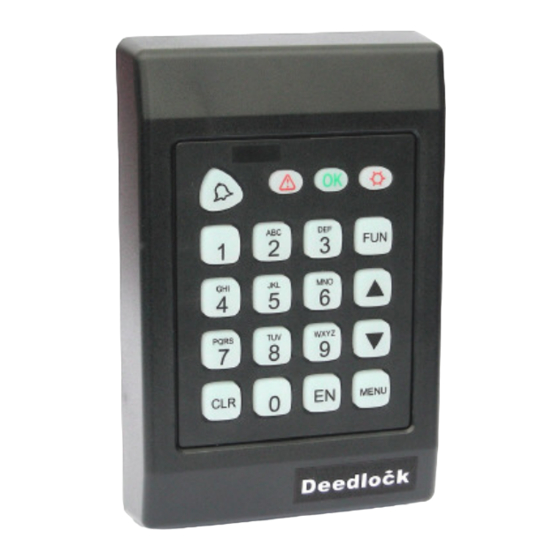
APX-03 Keypad & Proximity Reader
Contents:
Page 1. Product overview and Fixing instructions.
Page 2. Wiring detail for Electric Release/Strike - Wiring detail for Magnetic Lock.
Page 3. Wiring detail for Two Magnetic Locks - Wiring detail for Bell/Sounder.
Page 4. Initial Power up procedure - Programming overview - Adding a User Code.
Page 5. Adding a User Fob (Mode 2 User Fob only).
Page 6. Adding a User Fob and 4 Digit Group Code (Mode 3 User Fob + Group code) -
Deleting a Single Fob - Deleting a Group of Fobs (Mode 2 & 3).
Page 7. Restoring a Deleted Fob - Changing Lock open Time & Bell ringing time -
Changing the Master Code.
Page 8. Clearing Code & Fob data (Memory Reset) - Adding a new Master Fob if the
Original is Lost - Specifications.
Page 9&10. System Record Sheet and Fob Name & Number list.
Page 11. Troubleshooting Guide
Head Office: Securefast Plc. Unit 6, Cedar Business Centre, Cannock, Staffs. WS11 1QJ. Tel:01543-501600
Sales & Technical Office: Tate Colson. 1st Floor, Queen Anne House, 18 Eastbank Street, Southport, Merseyside. PR8 1DT. Tel: 01704-502801
a division of
Installation Instructions
Advertisement

Summary of Contents for Tate Colson APX-03
- Page 1 Page 9&10. System Record Sheet and Fob Name & Number list. Page 11. Troubleshooting Guide Head Office: Securefast Plc. Unit 6, Cedar Business Centre, Cannock, Staffs. WS11 1QJ. Tel:01543-501600 Sales & Technical Office: Tate Colson. 1st Floor, Queen Anne House, 18 Eastbank Street, Southport, Merseyside. PR8 1DT. Tel: 01704-502801...
-
Page 2: Important Points
Installation MUST be done by a Qualified Electrician/Installation Engineer and comply with current Standards & Legislation. The APX-03 must be connected to a Regulated 12v DC Power Supply with Minimum Load rated @ 1amp. The Maximum load on either Relay Must Not exeed 1amp (use seperate relay if above 1amp). - Page 3 APX-03 Keypad & Proximity Reader Wiring Details Fig.1 - Wiring detail for Electric Release including Exit Button Exit Button APX03 Keypad/Reader Com N/O Capacitor 474J 100JS Blue - Ground White - RQE Brown - Relay 1 Norm. Open Green - Relay 1 Norm. Closed*...
- Page 4 APX-03 Keypad & Proximity Reader Wiring Details Fig.3 - Wiring detail for Electric Lock with Current Draw 1amp or over EG: Two Magnetic Locks including Exit Button and Call Point Exit Button APX03 Keypad/Reader Capacitor Com N/O Emergency 474J 100JS...
-
Page 5: Initial Power-Up
APX-03 Keypad & Proximity Reader Programming Instructions Initial Power up Key to Indicators: = Error. = OK. = Power. On initial power up of the Keypad the Error, OK and Power indicators will light up. Wait for 3 long Bleeps, then a short Bleep followed by the Error and OK lights flashing. - Page 6 APX-03 Keypad & Proximity Reader Programming Instructions MODE 2 - User Fob only Note: The Keypad will hold up to 12,000 user Fobs which are split up into 20 Groups of 600 Fobs. Each group of Fobs must be numbered consecutively. Fobs can be programmed by number or by presenting the lowest number Fob then the highest number Fob.
- Page 7 APX-03 Keypad & Proximity Reader Programming Instructions MODE 3 - User Fob + 4 Digit Group code Mode 3 provides more security by allocating a group of user Fobs with a common 4 digit code which has to be entered after the Fob is recognised by the Keypad. When adding the batch of Fobs they must be programmed into a different group from those being used for Fob only access (Mode 2).
-
Page 8: Additional Programming Functions
APX-03 Keypad & Proximity Reader Programming Instructions MODE 2 & MODE 3 - Restoring a Deleted Fob To Restore a Deleted Fob: Example Indication Enter into Programming mode as shown on page 4. 2 Enter Function code 34 then EN... -
Page 9: Specifications
APX-03 Keypad & Proximity Reader Programming Instructions Additional Programming functions To Clear all Code & Fob data: Example Indication 1 Enter into Programming mode as shown on page 4. 2 Enter Function code 48 then EN FUN 48 EN OK indicator flashes... - Page 10 APX03 KEYPAD/PROXIMITY READER - SYSTEM RECORD SHEET UNIT LOCATION: DATE INSTALLED: INSTALLED BY: INSTALL ENGINEER: MASTER FOB No: USER CODES (4 DIGIT) Note: Master fob must be lowest fob number SLOT 01 SLOT 04 MASTER CODE: SLOT 02 SLOT 05 SLOT 03 FOB GROUP SLOT NUMBERS GROUP No: FIRST FOB No:...
- Page 11 FOB NUMBER & NAME LIST (CONT'D) NAME: NAME: FOB No: FOB No: Photocopy this sheet if required...
- Page 12 APX-03 Keypad/Proximity Reader - Troubleshooting Guide Fault / Problem Reason / Action required Power light is not illuminated Check input voltage is 12v DC (+/- 10%) at RED & BLACK wires. Make sure Positive is connected to RED & Negative connected to BLACK.
Need help?
Do you have a question about the APX-03 and is the answer not in the manual?
Questions and answers