Table of Contents
Advertisement
Advertisement
Table of Contents

Subscribe to Our Youtube Channel
Related Manuals for Catch Power GREEN

Summary of Contents for Catch Power GREEN
- Page 1 GREEN INSTALLATION & USERS GUIDE CATCH Power GREEN – Installation manual - Page 1...
- Page 2 Electric Shock Risk with CT’s CT’s must be fitted to insulated cables only. Ensure CT is terminated into the device before clamping onto cables. Catch Power GREEN – Installation manual - Page 2...
-
Page 3: Specifications
Max A/C Cable Size CT lead length IP Rating IP2X Operating Temperature range C to +45 Battery Compatible Size 100W x 110H x 50D (mm) Standards Conformity AS/NZS3100, AS/NZS CISPR 32:2015 Catch Power GREEN – Installation manual - Page 3... - Page 4 Case temperature can reach 60 Ensure the diverter is not placed next to anything that can be affected by moderate temperatures. 50mm 30mm 30mm 50mm Catch Power GREEN – Installation manual - Page 6...
- Page 5 1.1 – Detach mounting plate from unit. Remove the 4 screws from the bottom guard and remove the guard. Slide the mounting plate down towards the bottom of the unit then pull it out as shown. Catch Power GREEN – Installation manual - Page 6...
- Page 6 1.2 - Fix the mounting plate to a flat surface using the four bolt holes on the plate. Ø6mm Evenly distributed across mounting plate 1.3 - Drill cable entry holes based on dimensions shown. Catch Power GREEN – Installation manual - Page 6...
- Page 7 • in the same direction. Some electrical jurisdictions do not allow switches in the Off Peak • circuit, if this is your case then do not connect the off peak circuit. Catch Power GREEN – Installation manual - Page 7...
- Page 8 • Hot water isolator is not required if 20A double pole breaker • clearly label as hot water. Off Peak MUST be on the same phase as the MAINS terminal. • Catch Power GREEN – Installation manual - Page 6...
- Page 9 Ensure cables are position so that no long term load is applied to • terminal blocks. Ensure all terminal block screws are screwed in tight, even the • ones that are not used. Catch Power GREEN – Installation manual - Page 6...
- Page 10 It is vitally important the CT’s are pointing in the right direction. Electric Shock Risk with CT’s CT’s must be fitted to insulated cables only. Ensure CT is terminated into the device before clamping onto cables. Mains Catch Power GREEN – Installation manual - Page 8...
- Page 11 • Replace the bottom guard ensuring all cables are not touching the guard. • Replace all screws ensuring the tooth washers are used for the screws exposed at the top of the guard. Catch Power GREEN – Installation manual - Page 6...
- Page 12 If the diverting light is solid green it means the unit is as at 100%, which means Catch is sending as much power as the hot water element can handle.
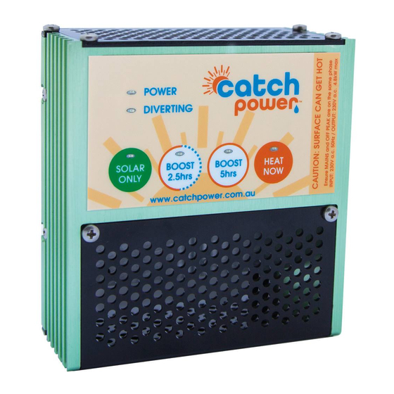
- Page 13 Each button on the control console represents a different mode of operation. You change modes by gently pressing on the round circle that represents each button. Catch will let you know if it has changed modes by the green LED lighting up on the button you have just pressed. 3. Heat Now Button The Heat Now mode is entered into by pressing the Heat now button.
Need help?
Do you have a question about the GREEN and is the answer not in the manual?
Questions and answers