Table of Contents
Advertisement
Quick Links
Advertisement
Table of Contents

Summary of Contents for sterling water treatment NEST series
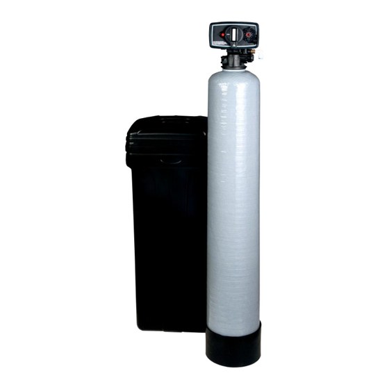
- Page 1 Installation Instructions and Owner’s Manual NEST & NST Series Tannin / Water Softening System First Sales, LLC 12630 US Highway 33 N Churubusco, IN 46723 Phone (260) 693-1972 Fax (260) 693-0602 NEST-NST Series Installation Manual 1811101.docx...
-
Page 2: Table Of Contents
Installation Instructions Page 4 Brine Tank Page 5 Bypass Valve Page 5 NST Series Time Clock Programming Page 7 NEST Series Programming Page 9 Specifications Page 11 Component Parts Breakdown & List Page 12 NST Control Valve Breakdown Page 13... -
Page 3: Pre-Installation Instructions
Pre-installation Instructions Description of the water softener system This tannin / water softener system includes a brine (salt) tank and a resin (media) tank with a backwashing control valve. Incoming water flows into the control valve and is directed down through the mixed bed ion exchange resin. - Page 4 Pre-installation Instructions (cont.) Location Considerations The proper location to install the water softener system will ensure optimum performance and satisfactory water quality. The following factors should be considered in selecting the location of the equipment. 1. The water softener should be installed after the pressure tank (private well system only) or after the water meter on municipal water.
-
Page 5: Installation Instructions
POSITION DRAIN ELBOW METER MODULE ELBOW LOCKNG CLIP CONTROL VALVE NEST Series (Electronic NST Series (Time Clock) Metered) FIGURE 2: Top View of Control Valve STEP 3: Place unit at desired installation position. DO NOT plug into electrical outlet at this time (see STEP 15 on page 6 or see STEP 10 on page 5). -
Page 6: Brine Tank
Installation Instructions (cont.) Connect one end of the 3/8” brine line to the control valve quick connect fitting. Insert the other STEP 7: end of the brine line through the hole in the brine tank and into the quick connect fitting on the safety brine valve. - Page 7 17 for Troubleshooting. For the NEST Series press the center “ADVANCE” button and the control valve will go to the brine draw position. Verify that the water level in the brine tank is dropping. Allow water level to drop below the salt grid before continuing.
-
Page 8: Nst Series Time Clock Programming
NST Series Time Clock Setting Instructions FIGURE 5: Front of Time Clock Timer Assembly How to set Time of Day: 1. Press and hold the red button to disengage the 24 hour gear. 2. Turn the large 24 hour gear until the actual time of day is at the time of day arrow. 3. - Page 9 NST Series Time Clock Setting Instructions (cont.) 4. Rotate the skipper wheel until the number 1 is at the red pointer. Each number represents a day. The number by the red pointer is tonight. 5. Slide the metal tabs outward on the desired days of regeneration. NOTE: The tannin / softener should be regenerated at least every 3 days to prevent fouling of the tannin reduction resin.
-
Page 10: Nest Series Programming
NEST Series Programming Advance Button FIGURE 6: Front of Electronic Meter Timer Assembly SET BUTTON 1. Press and hold “Set Button” for 5 seconds to enter Programming Mode. 2. When valve is in Programming Mode, press “Set Button” to confirm setting and advance to next menu option. - Page 11 NEST Series Programming (cont.) Enter Programming Mode: Press and Hold the SET Button for 5 seconds. Use Up Button to set current hour Use Up Button to set current minute Use Up Button to set AM/PM Use Up Button to set ADJUSTED Hardness...
-
Page 12: Specifications
Specifications UNIT MODEL NUMBER DESCRIPTION NST45 NST60 NEST45 NEST60 MEDIA VOLUME, ft HARDNESS CAPACITY, grains 24,000 29,000 Factory Salt @ 9 lb/ft (146 g/L) 24,000 29,000 TANNIN CAPACITY, ppm gallons 1,000 1,000 Factory Salt @ 9 lb/ft (146 g/L) 1,000 1,000 SERVICE FLOW RATES, gpm Cont. -
Page 13: Component Parts Breakdown & List
Component Parts Breakdown Unit Description NST45 NST60 NEST45 NEST60 Timeclock Valve N-1.5 Vlv N-2 Vlv Assy w/bypass Assy w/BP w/BP Electronic Valve NE-1.5 Vlv NE-2 Vlv w/bypass Assy w/BP Assy w/BP Mineral Tank MTP1054GR MTP1248GR Distributor D100S-54 D100S-48 Resin (2) H05P (3) H05P Tannin Resin (1) T05P... -
Page 14: Nst Control Valve Breakdown
NST Time Clock Control Valve Breakdown... -
Page 15: Nst Control Valve Parts List
NST Time Clock Control Valve Parts List REF # Part Number Description N-PH Power head, Time clock 60102-00 Piston Assembly 60125 Seal and Spacer Kit 60084-0102NMS Injector and Drain Housing Assy, Blank DLFC, #1 Injector, 0.5 GPM BLFC 60032 Brine Stem Assembly 60900-41 Coupling, Adapter S/ASSY 60040SS... -
Page 16: Nest Control Valve Breakdown
NEST Metered Control Valve Breakdown... -
Page 17: Nest Control Valve Parts List
NEST Metered Control Valve Parts List REF # Part Number Description NE-PH Powerhead, Metered NE-FC Front Panel and Circuit Board Assembly 60102-NES Piston Assembly 60125 Seal and Spacer Kit 60084-0123NES Injector and Drain Housing Assy, 2.4 gpm DLFC, #1 Injector, 1 GPM BLFC 60032 Brine Stem Assembly EM-1... -
Page 18: Troubleshooting
Troubleshooting PROBLEM CAUSE SOLUTION A. Ensure permanent electrical service A. Electrical service to unit has been to unit (switch, circuit breaker, plug, interrupted etc.) 1. Softener fails to regenerate B. Meter cable not inserted into meter B. Insert meter cable into meter C. - Page 19 Troubleshooting (cont.) D. Redistribute gravel to cover D. Gravel underbed shifted to one side distributor PROBLEM CAUSE SOLUTION A. Iron exceeds recommended level A. Test incoming water supply and or is not “Clearwater” iron or iron install OXY Series iron filter prior to bacteria is present softener, as needed 7.
-
Page 20: Ten Year Limited Warranty
TEN YEAR LIMITED WARRANTY WARRANTY – First Sales, LLC. warrants this water conditioner against any defects that are due to faulty material or workmanship during the warranty period. This warranty does not include damage to the product resulting from accident, neglect, misuse, misapplication, alteration, installation or operation contrary to printed instructions, or damage caused by freezing, fire, flood, or Acts of God.
Need help?
Do you have a question about the NEST series and is the answer not in the manual?
Questions and answers