Table of Contents
Advertisement
Quick Links
M
P
C
ASSA
RODUCTS
ORPORATION
May 23, 2017
PulStar
®
Ultrasonic Sensors
Installation & Operation Guide
May 23, 2017
The PulStar Sensor product line listed in the introduction of this manual
complies with the European Council EMC Directive 2004/108/EC (EMC) and Low
Voltage Directive 2006/95/EC (LVD).
Copyright © 2016 by Massa Products Corporation. All rights reserved.
Installation and Operation Guide
MassaSonic® PulStar® Ultrasonic Sensors
Advertisement
Table of Contents

Summary of Contents for Massa MassaSonic PulStar/150 V
- Page 1 The PulStar Sensor product line listed in the introduction of this manual complies with the European Council EMC Directive 2004/108/EC (EMC) and Low Voltage Directive 2006/95/EC (LVD). Copyright © 2016 by Massa Products Corporation. All rights reserved. Installation and Operation Guide MassaSonic® PulStar® Ultrasonic Sensors...
-
Page 2: Table Of Contents
ASSA RODUCTS ORPORATION May 23, 2017 Table of Contents Section Page 1 Introduction ......................1 2 Quick Guide on Getting Started ..............2 Mounting PulStar Sensors ......................... Operating a PulStar Sensor without a Computer ................Operating a PulStar Sensor Connected to a Computer ............... Operating Up to 32 Sensors Simultaneously Using a Multi-Drop Configuration ...... -
Page 3: Introduction
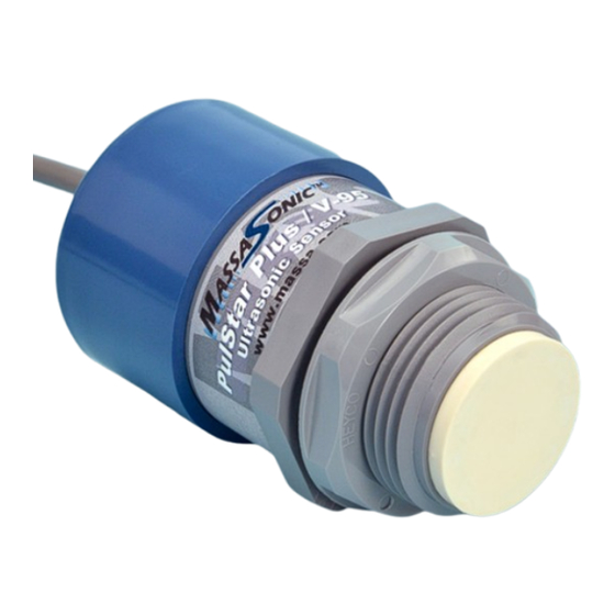
May 23, 2017 Introduction The MassaSonic® PulStar® Ultrasonic Sensors combines Massa’s 70 plus years of experience in electroacoustics with state-of-the-art analog and microprocessor hardware and software design. The result is the most versatile, easiest to use ultrasonic sensor on the market. The PulStar Family of Sensors, listed in the following table, consist of sensors that operate at different frequencies which determine sensing range. -
Page 4: Quick Guide On Getting Started
An optional Mounting Bracket can also be purchased, as shown in Figure 1. Figure 1 Photograph of a Massa PulStar/150 Sensor Attached to an Optional Mounting Bracket Operating a PulStar Sensor without a Computer •... -
Page 5: Operating A Pulstar Sensor Connected To A Computer
Connect the sensor’s power leads as shown in Figure 3. If wiring the sensor’s Vout or Iout lead, connect it as well. • Obtain a USB/RS-485 converter (see Massa’s website for purchase) and follow instructions to properly configure it to a laptop. Only plug it into your laptop’s USB port when indicated. •... - Page 6 ASSA RODUCTS ORPORATION May 23, 2017 Quick Guide on Getting Started (continued) Figure 4 Example of the Status and Setup Screen for a Standard PulStar Sensor Figure 5 Example of the Status and Setup Screen for a PulStar PLUS Sensor Installation and Operation Guide MassaSonic®...
-
Page 7: Operating Up To 32 Sensors Simultaneously Using A Multi-Drop Configuration
May 23, 2017 ASSA RODUCTS ORPORATION Quick Guide on Getting Started (continued) Operating Up to 32 PulStar Sensors Simultaneously in a Multi-Drop Configuration Sensors that will be wired together on the same RS-485 bus will first require that each sensor be programmed with its own unique ID Tag. -
Page 8: Product Description
ORPORATION Product Description This section contains a general overview of the PulStar™ Family of Ultrasonic Sensors. For detailed information on any specific sensor model, please refer to the datasheet located on the Massa website (www.massa.com). DC Power Requirements PulStar Sensors are powered from 12 to 24 V DC sources, either batteries or power supplies, that are capable of supplying currents of approximately 30 mA (Vout models) and up to 50 mA (Iout models). - Page 9 ASSA RODUCTS ORPORATION May 23, 2017 Product Description (continued) In the ‘Linear Mode’, the user can set the values for the following programming options using the Status and Setup Screen shown in Figure 4. 1) Set any Output Voltage value from 0 V DC to 10.25 V DC (or current from 0mA to 20.5 mA) for the Zero Distance.
-
Page 10: Rs-485 Port
To learn more about the specific operational details of this communication port, see the PulStar Sensors Serial Communications Guide located on the Massa website (www.massa.com). Multi-drop Operation If planning to connect more than one PulStar Sensor on the same communications bus, each must be programmed with its own unique ‘ID Tag’... -
Page 11: Installing Massasonic Software
The minimum requirements to run MassaSonic Ultrasonic Sensor Software program is a PC operating under Windows ® 10, 8, 7, or XP operating systems. This software can be downloaded from the Massa’s website (www.massa.com). Start by running ‘setup.exe’, and the screen shown in Figure 9 will be displayed. -
Page 12: Status And Setup Screen
May 23, 2017 ASSA RODUCTS ORPORATION Status and Setup Scree Establishing Communication between a PC and the PulStar Sensor Once the MassaSonic Software has been installed and program executed, the PC’s comm port assigned for the USB to RS-485 Converter must be determined. Use the drop down menu item Getting Started and follow... -
Page 13: Status Box Of The Status And Setup Screen
ASSA RODUCTS ORPORATION May 23, 2017 Status and Setup Screen (continued) Status Box of the Status and Setup Screen The ‘Status’ box displays the various parameters for the particular PulStar Sensor whose ‘ID Tag’ is displayed in the ‘Sensor Selection’ box of the Status and Setup Screen. This field is updated approximately every ¼... -
Page 14: Editing A Sensor's Parameters
ASSA RODUCTS ORPORATION May 23, 2017 Status and Setup Screen (continued) Editing the PulStar Sensor Parameters The Status and Setup Screen provides status information and all the operating parameters for the sensor as shown in Figure 12. Editing is performed using standard Windows ®... -
Page 15: Sensor Selection Box Of The Status And Setup Screen
May 23, 2017 ASSA RODUCTS ORPORATION Status and Setup Screen (continued) Sensor Selection Box of the Status and Setup Screen ‘ID TAG’’ The ID Tag is a programmable sensor address that allows multiple sensors to be connected to the same pair of wires of a communications bus. -
Page 16: Mode Selection For Output Voltage (Or Current Out) Box Of The Status And Setup Screen
ASSA RODUCTS ORPORATION May 23, 2017 Status and Setup Screen (continued) Mode Selection for Output Voltage Box of the Status and Setup Screen The ‘MODE SELECTION for OUTPUT VOLTAGE’ box of the Status and Setup Screen allows programming the sensor to operate in either the ’Linear Mode’ or the ‘Switch Mode’. For current output models, the display will indicate ’MODE SELECTION for OUTPUT CURRENT’. - Page 17 May 23, 2017 ASSA RODUCTS ORPORATION Status and Setup Screen (continued) ‘Switch Mode Settings’ Box of the Status and Setup Screen The Switched Setpoint Output Mode (‘Switch Mode’) allows the state of Vout to switch between 0 and 10.25 V DC based on the relationship of the measured Target Distance to the ‘Close Setpoint Distance’...
-
Page 18: Sampling Settings Box Of The Status And Setup Screen
Target Distance can be entered for the ‘Sample Rate’. This rate can be between 0.1 samples/sec. up to the sensor’s maximum specified sampling rate. (This is model dependent. Refer to the datasheet located on the Massa website at www.massa.com for the particular sensor being used.) -
Page 19: Miscellaneous Box Of The Status And Setup Screen
ASSA RODUCTS ORPORATION May 23, 2017 Status and Setup Screen (continued) Miscellaneous Box of the Status and Setup Screen The ‘Miscellaneous’ box, shown in Figures 21 and 22, is used to select different methods of ‘Temperature Compensation’ to be used by the sensor to calculate the speed of sound in order to obtain an accurate Target Distance measurement. -
Page 20: Messages Box Of The Status And Setup Screen
ASSA RODUCTS ORPORATION May 23, 2017 Status and Setup Screen (continued) Messages Box of the Status and Setup Screen Messages will be displayed in this box, such as “Searching for Sensors on Port 1…” as shown in Figure 23, errors, such as user inputs that are out of parameter limits, are also displayed, as shown in Figure 15. -
Page 21: File Tab (Saving & Recalling Sensor Settings)
ASSA RODUCTS ORPORATION May 23, 2017 Status and Setup Screen (continued) File Tab File Sensor register settings can be saved and recalled using the drop down menu tab. This function allows the convenience of programming numerous sensors with the same settings. See Figure 25. Figure 25 Example Showing ‘Save Data’... -
Page 22: Tools Tab (Calibration Of The Voltage Or Current Output)
ASSA RODUCTS ORPORATION May 23, 2017 Status and Setup Screen (continued) Tools Tab Tools dropdown menu contains the menu item to calibrate the Voltage Output (or Current Output for Iout models). Each sensor is calibrated at the factory for 10.00 V or 20.00 mA so in most instances, the sensor does not need to be calibrated. -
Page 23: Tools Tab (Firmware Update)
‘Program Firmware’: Allows the user to update the sensor’s firmware if new versions are available (see Massa’s website). Download any new firmware to your PC and select the file using the Browse button. Click the ‘Program Sensor’ button and wait for the sensor firmware to be completely uploaded. See Figure 31 below. - Page 24 Certain applications may require custom sensitivity adjustments that can be done with the PLUS models. Consult Massa Products for additional information. Figure 34 Ultrasonic Waveform (1 of 2 waveforms available) Diagnostic waveforms can be saved and recalled using the ‘Save Data’...
-
Page 25: Setting Tab
ASSA RODUCTS ORPORATION May 23, 2017 Status and Setup Screen (continued) Settings Tab Figure 36 shows the selection options for the ‘Setting’ drop down menu. Figure 36 The ‘Settings’ Drop Down Menu Selections of the Status and Setup Screen ‘Display Default Settings’: Displays the Factory Default values. Either cancel or program these values into your sensor. -
Page 26: Getting Started Tab
Figure 39 shows the selection options for the ‘Help’ drop down menu. Figure 39 ‘Help’ Drop Down Menu Selections ‘Help system’: Help is available via product manual available at www.massa.com. ‘About This Program’: If this option is selected the MassaSonic™ Software version number will be displayed, as shown in Figure 41. -
Page 27: Factory Default Programmed Settings
Self-heating Correction = enabled (checked) Minimum and Maximum sensing ranges are different for each model in the PulStar Sensor Family. Consult the Datasheet located on the Massa website (www.massa.com) for the specific sensor model to obtain its minimum and maximum sensing ranges. -
Page 28: Troubleshooting
, computed as θ follows (for value of , see Table in Section 1 or the datasheet for the specific model of sensor on the Massa website at www.massa.com): θ dia D ( ) 2 tan ... - Page 29 ASSA RODUCTS ORPORATION May 23, 2017 Terminology (continued) Hysteresis: The distance between the operating point when a target approaches a setpoint and the release point when the target moves away from a setpoint towards its original position. ID Tag: A unique sensor programmed value (address) from 1 to 32 which identifies the sensor in a multi-drop communications loop.
-
Page 30: Wire Color Code
Purchaser. The obligation under this warranty is limited to the repair or replacement at MASSA’S sole discretion of any MASSA product returned to MASSA or to an authorized field service station. OTHER THAN AS... -
Page 31: Appendix A Sensor Start Up Timing
ASSA RODUCTS ORPORATION May 23, 2017 Appendix A Sensor Start up Timing The sensor power up time ready to report a valid output is based on several sensor settings and target conditions. These include Sample Rate, Average, and No Echo Timeout. The following are formulas based on these settings and conditions: Model PulStar with minimum sensing range enabled: Sensor Startup Time (valid target): 0.25 seconds + (2 x Average x Sample Rate in seconds)
Need help?
Do you have a question about the MassaSonic PulStar/150 V and is the answer not in the manual?
Questions and answers