Table of Contents
Advertisement
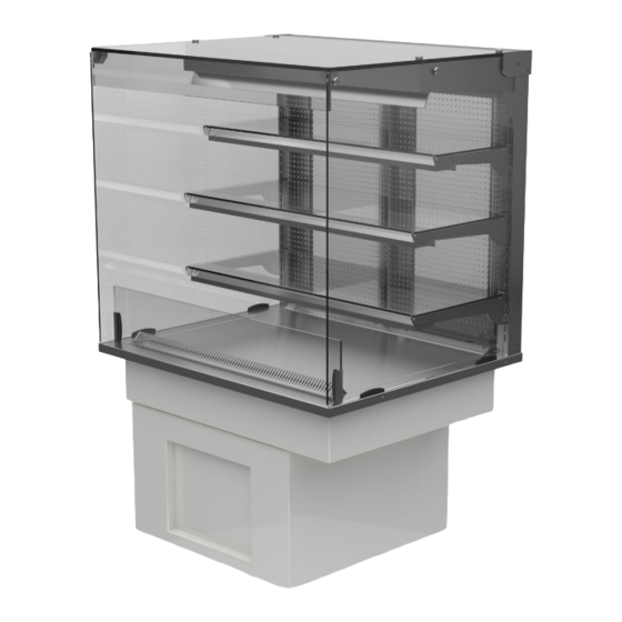
vision
part of the idesign range
Operation and Maintenance Manual
Chilled Displays
freestanding
Counterline Limited
Randles Road
Knowsley Business Park
Merseyside
L34 9HZ
United Kingdom
aire
tel: + 44 (0)151 548 2211
fax: + 44 (0)151 549 2179
service enquiries: servicelog@counterline.co.uk
spare parts enquiries: spareparts@counterline.co.uk
general enquiries: enquiries@counterline.co.uk
web: www. counterline.co.uk
drop-ins
01-2018
Advertisement
Table of Contents

Subscribe to Our Youtube Channel
Summary of Contents for Counterline vision aire
- Page 1 Counterline Limited tel: + 44 (0)151 548 2211 fax: + 44 (0)151 549 2179 Randles Road Knowsley Business Park service enquiries: servicelog@counterline.co.uk Merseyside spare parts enquiries: spareparts@counterline.co.uk general enquiries: enquiries@counterline.co.uk L34 9HZ United Kingdom web: www. counterline.co.uk 01-2018...
-
Page 2: Table Of Contents
Contents 1. OPERATION Switching Your Vision Chilled Display Unit On Page 3 Fault When Switching On Page 3 Temperature Control Page 4 Defrost Cycles Page 4 Display Lighting Page 5 Loading With Food Page 5 Chilled Vision Sliding Rear Doors Page 5 Shelf Adjustment Page 5-6... - Page 3 Important Information IMPORTANT Counterline Ltd cannot be held responsible for any accidents or injuries sustained through misuse or improper operation / maintenance of its products. Please follow our guidelines set out within this handbook for safe working practice. At the de- sign stage, please ensure that the counter understructure can take the weight of the display(s), and that adequate provision has been made for lifting and positioning the display, to avoid risk of damage or injury.
-
Page 4: Operation
Operation OPERATION It is essential that you read the instructions carefully and follow all of the cleaning and maintenance instructions. Failure to do so can result in premature failure that will not be covered by warranty. Vision chilled display units are designed to merchandise chilled food maintaining food temperatures by using re-circulated cold air. -
Page 5: Temperature Control
Operation 1.2 - TEMPERATURE CONTROL In the Vision system of chilled food display, the food temperature is maintained at or below 5 °C by a stream of re-circulated cold air. The air blows across the display deck, coming from grilles or holes on the operators side and returning to the fans via a grille at the customer’s side. -
Page 6: Loading With Food
Operation 1.5 - LOADING WITH FOOD • Vision chilled display units are designed to merchandise food that is already at a temperature of 3-5 deg C. • They are not designed to cool food from ambient temperature. • It is essential that all food and beverages have therefore been chilled to this temperature before being placed in the display. -
Page 7: Installation Of Wall-Sited Chilled Vision Displays
Operation 1.8 - INSTALLATION OF WALL-SITED CHILLED VISION DISPLAYS It is important that any free standing chilled wall unit is positioned correctly to ensure that an adequate intake and exhaust airflow is provided. This has been achieved by the fitting of rear wall stops 100mm in depth as standard. These stops are supplied loose together with fixings inside the O&M manuals. -
Page 8: Cleaning
Cleaning 2.0 - CLEANING SAFETY NOTE Before commencing any cleaning operation the Idesign unit must be isolated from the mains supply by either removing the supply plug from its socket or switching off at the local isolator. NB: Switching off using the power switch on the control panel does not fully isolate the unit. Under no circum- stances must a pressure washer or hosepipe be used in the vicinity of this unit. - Page 9 Cleaning …flat surface protected by soft cloths. The glass ends can then be slid forward until they release from the channels, when they can be lifted clear of the unit and set aside on a surface protected by soft cloths. They can then be cleaned on both sides.
-
Page 10: Rear Air Guides
Cleaning 2.4 - REAR AIR GUIDES • Vision chilled displays use vertical perforated panels behind the shelves to guide the chilled air around the unit. • In fixed back units they are polished stainless steel, in units with rear doors they are clear plastic. •... -
Page 11: Cleaning Chilled Display Main Tank
Cleaning 2.5 - CLEANING CHILLED DISPLAY MAIN TANK Note: This operation must be carried out monthly with the display disconnected from the electrical supply. supply. • If your display is fitted with a full height sneeze screen, you will need to remove it before attempting to carry out this cleaning operation. -
Page 12: Condensing Unit Finned Coil
Cleaning 2.6 - CONDENSING UNIT FINNED CONDENSER WILL BE SITUATED IN EITHER OF THE SHOWN POSITIONS COIL This must be cleaned monthly Located under the display is the condensing unit. This can be accessed for cleaning by either removing a grille in the fascia panelling of the counter or by removing the panel itself. -
Page 13: Automatic Evaporating Drip Tray
Cleaning 2.7- AUTOMATIC EVAPORATING TRAY • Isolate the display from the electrical supply and then allow the drip-tray to cool down for 30 mins or so before touch- ing. • The drip tray is located under the right hand end of the display when viewed from the rear. It can be accessed for clean- ing by either removing a grille in the rear panelling of the counter or by removing the panel itself. -
Page 14: Trouble-Shooting
Trouble-shooting 3.0 - BUILD UP OF ICE ON THE COIL In conditions of high humidity it is possible for ice to accumulate on the coil, and not be fully cleared by the defrost system. This problem is usually only likely to occur on units operating 24hours a day in conditions of high humidity. The result will be a failure to maintain temperature, as airflow through the coil is restricted. -
Page 15: Self Help Guide
IMPORTANT: Please ensure you have your serial number before calling. This can be located in the center of the gantry controller fascia plate. Address: Counterline Ltd, 12 Randles Road, Knowsley Business Park, Merseyside, L34 9HZ Telephone: +44 (0)151 548 2211...
Need help?
Do you have a question about the vision aire and is the answer not in the manual?
Questions and answers