Advertisement
Quick Links
INSTALLATION
INSTRUCTIONS
I - Ship ping And Pack ing List
Package 1 of 2 contains:
1 - Energy Recovery Ventilator Assembly
1 - Outdoor Fresh Air Hood w/ Filter
1 - Outdoor Exhaust Hood w/ Barometric Dampers
Package 2 of 2 contains:
1 - Balancing Damper Assembly
1 - Platform Support Rail
2 - Door Panels
1 - Bag Assembly
1 - Roll of ¾" x 1 ¼" gasket
1 - 272" of
" x ½" gasket
1
8
1 - Field Wiring Harness for Low Voltage with
ECO 1001 economizer control board
10 - #14 Screws
30 - #10 x ½" Gold Screws
1 - Installation Instructions
UERV
II - Ship ping Dam age
Check unit for shipping damage. Receiving party should
contact last carrier immediately if shipping damage is
found.
III - Gen eral
These instructions are intended as a general guide and do
not supersede local codes in any way. Authorities having
jurisdiction should be consulted before installation.
IV - Re quire ments
When installed, the unit must be electrically wired and
grounded in accordance with local codes or, in absence of
local codes, with the current National Electric Code,
ANSI/NFPA No. 70.
V - Ap pli ca tion
Unitary Energy Recovery Ventilator (UERV) are used with
15 to 30 ton rooftop units equipped with a balancing
damper assembly. These wheels conserve energy by
mixing warmer air with cooler air in the following manner:
UNITARY ENERGY RECOVERY VENTILATOR
MODEL VR028A15M/H & VR028A25H (STATIONARY)
E n e r g y r e c o ve r y C O M P O N E N T
certified to the AHRI Air-to-Air Energy
Recovery Ventilation Equipment
Certification Program in accordance
w ith AHRI Standard 1060-2000.
Actual performance in packaged
equipment may vary.
PAGE 1
MAXA-MI$ER
5257527-UAI-A-0616 / R28A-18YSDW
Recovery Wheel Mode
The Recovery Wheel mode is accomplished by two
blowers providing continuous exhaust of stale indoor air
and replacement by equal amount of outdoor air. Energy
recovery is achieved by slowly rotating the energy
recovery wheel within the cassette frame work. In winter,
the UERV adsorbs heat and moisture from the exhaust air
stream during one half of a complete rotation and gives
them back to the cold,drier intake air supply during the
other half rotation. In summer, the process is automatically
reversed. Heat and moisture are absorbed from incoming
fresh air supply and transferred to the exhaust air stream.
This process allows outdoor air ventilation rates to be
increased by factors of three or more without additional
energy penalty or increase in size of heating or air
conditioning systems.
VI - Rig ging Unit For Lift ing
1. Maximum weight of unit is — 750 Lbs. (Crated)
2. Remove crating. Then remove access panel to
retrieve bag assembly. Replace access panel.
3. All panels must be in place for rigging.
4. Lifting lugs are supplied with the unit. Loosen machine
bolts and rotate lifting lug.
WARNING
Electric shock hazard. Can cause injury
or death. Before attempting to perform
any service or maintenance, turn the
electrical pow er to unit OFF at
disconnect switch(es). Unit may have
multiple power supplies.
CAUTION
Danger of sharp metallic edges. Can cause injury.
Take care when servicing unit to avoid accidental
contact with sharp edges.
VII - In stal la tion
1. Disconnect all power to the rooftop unit.
Note: Ensure that no power source is connected to the
unit. If the economizer is installed and power is
applied, de-energize all power sources to the unit
and use Lockout - Tag-out procedures. There may
be multiple power inputs to unit, so validate that all
power sources are de-energized and tagged.
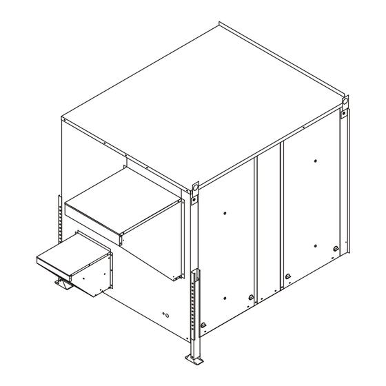
2. Remove the rooftop units horizontal and return air
access panels. Remove and discard any hoods,
power exhaust equipment or economizer. See Figure
1.
ETL Certified per UL 1995
and CSA 22.2
Advertisement

Related Manuals for York International VR028A15H

Summary of Contents for York International VR028A15H
- Page 1 MAXA-MI$ER INSTALLATION UNITARY ENERGY RECOVERY VENTILATOR MODEL VR028A15M/H & VR028A25H (STATIONARY) INSTRUCTIONS 5257527-UAI-A-0616 / R28A-18YSDW E n e r g y r e c o ve r y C O M P O N E N T certified to the AHRI Air-to-Air Energy Recovery Ventilation Equipment ETL Certified per UL 1995 Certification Program in accordance...
-
Page 2: Installation Instructions
MAXA-MI$ER INSTALLATION UNITARY ENERGY RECOVERY VENTILATOR MODEL VR028A15M/H & VR028A25H (STATIONARY) INSTRUCTIONS 5257527-UAI-A-0616 / R28A-18YSDW BALANCING DAMPER FILTER ACCESS REMOVE Figure 1 3. Remove the return duct cover from the floor of the Figure 4 RTU. REINSTALL CENTER POST 4. Remove the 9 screws holding the painted outside center post between the horizontal return air openings. - Page 3 MAXA-MI$ER INSTALLATION UNITARY ENERGY RECOVERY VENTILATOR MODEL VR028A15M/H & VR028A25H (STATIONARY) INSTRUCTIONS 5257527-UAI-A-0616 / R28A-18YSDW PLATFORM SUPPORT RAIL Figure 10 Figure 7 13. Lift the UERV at least 3' (feet), remove the nut and bolt assembly and slide the telescoping leg out of the guide.
- Page 4 MAXA-MI$ER INSTALLATION UNITARY ENERGY RECOVERY VENTILATOR MODEL VR028A15M/H & VR028A25H (STATIONARY) INSTRUCTIONS 5257527-UAI-A-0616 / R28A-18YSDW 19. Secure the side flanges of the UERV to the holes in the adaptor panels installed earlier using the provided screws. 20. Check along the edges where the UERV meets the adaptor panels and where the adapter panels meet FUSE BLOCK the RTU and seal where necessary.
- Page 5 MAXA-MI$ER INSTALLATION UNITARY ENERGY RECOVERY VENTILATOR MODEL VR028A15M/H & VR028A25H (STATIONARY) INSTRUCTIONS 5257527-UAI-A-0616 / R28A-18YSDW During both the summer and winter, the UERV transfers A - Return Damper Set tings moisture entirely in the vapor phase. This eliminates wet Manually adjust position of dampers. This is accomplished surfaces that retain dust and promote fungal growth as well by loosing and tightening set screw on positioning rod.
- Page 6 MAXA-MI$ER INSTALLATION UNITARY ENERGY RECOVERY VENTILATOR MODEL VR028A15M/H & VR028A25H (STATIONARY) INSTRUCTIONS 5257527-UAI-A-0616 / R28A-18YSDW Belt Alignment SEGMENT RETAINER CATCH Proper alignment is essential to maintain long V-Belt life. SEGMENT RETAINER Belt alignment should be checked every time belt WHEEL RIM maintenance is performed, each time the belt is replaced, and whenever sheaves are removed or installed.
- Page 7 MAXA-MI$ER INSTALLATION UNITARY ENERGY RECOVERY VENTILATOR MODEL VR028A15M/H & VR028A25H (STATIONARY) INSTRUCTIONS 5257527-UAI-A-0616 / R28A-18YSDW York UERV Model Nomenclature V R 028 A12 H 4 A L2 1 Prod uct Cat e gory Prod uct Gen er a tion V = Ventilator 1 = First Generation Wheel Type Ad di tional Op tions...
- Page 8 PAGE 8...
- Page 9 PAGE 9...
- Page 10 COMPONENT CODE A131 Fixed Relay Board J152 Jack, Transformer (High Voltage) P153 Plug, Field Harness Motor, Exhaust Air J153 Jack, Field Harness P160 Plug, Damper Intake Motor Harness Motor, Intake Air J160 Jack, Damper Intake Motor Harness P161 Plug, Damper Exhaust Motor Harness Motor, Desiccant Wheel J161 Jack, Damper Exhaust Motor Harness...
- Page 11 ERV UNIT WIR ING DIAGRAM Desiccant Wheel for Rooftop Unit 208-230/460V/575V (3 PH) Unit#: 82-R2818/19XX-23/-33/-43 PAGE 11...
-
Page 12: Equip Ment Lay Out
EQUIP MENT LAY OUT PAGE 12... - Page 13 MAXA-MI$ER INSTALLATION UNITARY ENERGY RECOVERY VENTILATOR MODEL VR028A15M/H & VR028A25H (STATIONARY) INSTRUCTIONS 5257527-UAI-A-0616 / R28A-18YSDW In order for the ERV to operate with maximum effectiveness the Smart Equipment Control (SEC) must have the latest 3.1 (or greater) firmware installed. In order to determine the version of firmware present within the control follow the menu steps below.
- Page 14 MAXA-MI$ER INSTALLATION UNITARY ENERGY RECOVERY VENTILATOR MODEL VR028A15M/H & VR028A25H (STATIONARY) INSTRUCTIONS 5257527-UAI-A-0616 / R28A-18YSDW 1. Place USB Flash Drive into USB port on controller Screen will read: (Note: Please be sure a backup to a USB drive >View Ver (Version) before updating the firmware).
- Page 15 MAXA-MI$ER INSTALLATION UNITARY ENERGY RECOVERY VENTILATOR MODEL VR028A15M/H & VR028A25H (STATIONARY) INSTRUCTIONS 5257527-UAI-A-0616 / R28A-18YSDW 8. Press ENTER again. Screen will read FWU WAIT then the program will load. This could take up to 10 minutes or more. The screen contents will change several times during the update so be patient…...
- Page 16 START UP INFORMATION SHEET VOLTAGE - UERV UNIT In com ing Volt age L1-L2 L1-L3 L2-L3 Run ning Volt age L1-L2 L 1-L3 L2-L3 Sec ond ary Volt age C (black) to G (green) Volts* C (black) to W (white) Volts* * With thermostat calling.
Need help?
Do you have a question about the VR028A15H and is the answer not in the manual?
Questions and answers