Table of Contents
Advertisement
Quick Links
Advertisement
Chapters
Table of Contents

Related Manuals for Solar-Log 50

Summary of Contents for Solar-Log 50
- Page 1 Manual V.4.2.0 Solar-Log 50...
- Page 2 Publisher: Solare Datensysteme GmbH Fuhrmannstr. 9 72351 Geislingen-Binsdorf Germany International support Tel.:+49 7428 9418 -640 Fax:+49 7428 9418 -280 e-mail: support@solar-log.com Italy Technical support: +39 0471 631032 e-mail: italy-support@solar-log.com France Technical support: +33 97 7909708 e-mail: france-support@solar-log.com Switzerland Technical support: +41 565 355346 e-mail: switzerland-fl-support@solar-log.com...
-
Page 3: Table Of Contents
Connector Assignments and Wiring ..............13 Notes on wiring the connections ......................... 13 2 x RS485 (A/B) or 1 x RS422 ..........................14 Connecting the inverters ..................15 Switch off the inverters and the Solar-Log™....................16 Connecting accessories ....................17 External power meter ............................... 17 8.1.1 External power meters/accumulating meters .................... - Page 4 Installation ........................20 10.1 Connect the Solar-Log™ to a network / PC....................20 10.2 Initial set up of the Solar-Log 50 ......................... 21 Go to the Main Menu....................22 11.1 Operating the Main Menu of the Solar-Log™ ....................25 11.1.1...
- Page 5 13.4.10 Percentage of consumption for an adjustable reduction ................58 13.5 Editing Data ................................58 13.5.1 System backup ................................58 13.5.2 Backup ................................... 61 13.5.3 Reset ....................................63 13.6 System Configuration ............................. 64 13.6.1 Access control ................................64 13.6.2 HTTPS .................................... 65 13.6.3 Language/Country/Time ............................
- Page 6 19.1 Cleaning tips .................................. 85 19.2 Care tips ................................... 85 Disposal ...........................86 Appendix .........................87 21.1 Internet ports ................................. 87 Dimensions ........................88 List of Figures ........................89...
-
Page 7: Introduction
This manual is intended for use by solar energy technicians and professional electricians, as well as So- lar-Log 50 users. It should be noted that the installation and commissioning of the individual components is only to be performed by properly trained specialists. Refer to Chapter 4 "Safety information" for more information. -
Page 8: Safety Information
Safety information 2 Safety information In order to protect people, the device itself, and other equipment, please pay attention to the following before handling the product: • the content of this manual, • the safety information, • the warning signs and type plates attached to the product. Note: All the actions described in this manual for wiring and working on the individual components must be carried out only by specially trained electricians. -
Page 9: Electric Current
Before picking up the component, ground yourself by holding the protective conductor (PE) or the unpainted part of the inverter housing. Caution Damage to the electrical components of the Solar-Log™ due to the wiring of the So- lar-Log™! Disconnect the Solar-Log™ from the power supply. -
Page 10: Package Contents And Installation
It can mounted on the wall (see illustration below) or on a top-hat rail (refer to the Solar-Log™ dimensions in chapter 22). Power can come from a DIN rail power supply or a 24V power supply with an adapter. -
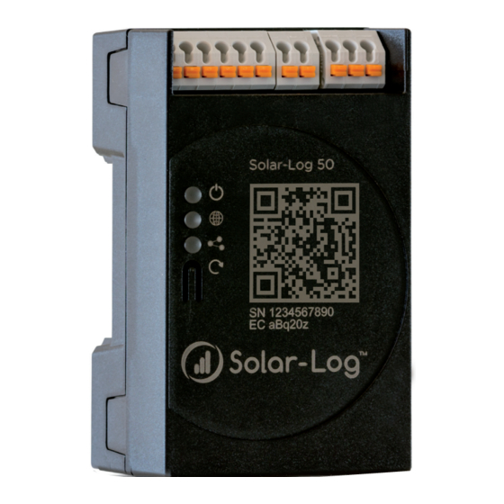
Page 11: Solar-Log 50 Connections
Top Connections Solar-Log 50 2x RS485 or RS422 Input: 24 V/ 1A DC Ethernet US B Pins without function Fig.: Top Connections – Solar-Log 50 Solar-Log 50 Top connections 2 x RS485 Connection for inverters and or RS422 additional accessories Input:... -
Page 12: Bottom Connections Solar-Log 50
Solar-Log 50 Connections 5.2 Bottom Connections Solar-Log 50 Fig.: Bottom connections Solar-Log 50 Bottom of the Solar-Log 50 USB connection. Suitable for USB sticks. Not suitable for a connec- tion to a PC / laptop. Network Ethernet network interface, 10/100 Mbit... -
Page 13: Connector Assignments And Wiring
Sets of prefabricated cables are available as accessories suitable for the inverter concerned. The length of these cable sets is 3 m. • If you want to connect several inverters to Solar-Log™, you need suitable cables and connectors to connect the inverters to each other. •... -
Page 14: Rs485 (A/B) Or 1 X Rs422
Connector Assignments and Wiring 6.2 2 x RS485 (A/B) or 1 x RS422 Use the provided terminal blocks when connecting inverters or accessories to the RS485 or RS422 inter- face. RS485 Connection Block Pin Assignment RS485-A RS485-B Assignment Assignment Data+ 12 V Ground / GND Data-... -
Page 15: Connecting The Inverters
Always read the manufacturer-specific instructions for connecting the data cable. You will find these in- structions in the manufacturer's documentation. However, when assigning the inverter wiring on the Solar-Log™, follow the instructions in this manual, oth- erwise the inverters will not be detected by Solar-Log™. -
Page 16: Switch Off The Inverters And The Solar-Log
Switch off the inverters and the Solar-Log™. Switching inverters off Before a making a cable connection between the Solar-Log™ and the connections inside the inverter and before installing an interface card in the inverter, always turn off all of the inverters first. -
Page 17: Connecting Accessories
The energy recorded by these meters can be used for numerous applications: • Generator Mode: This mode is used, for example, for inverters that are not directly supported by Solar-Log™. • Total yield meter: This mode is used to record the energy production of several inverters. -
Page 18: External Power Meters/Accumulating Meters
Phase 1 supplies 3 kW via an inverter (single phase). Phase 2 draws 2 kW (energy) Phase 3 draws 1 kW (energy) With an accumulating meter, this results in a total of 0 kW. Examples of accumulating meters are the Janitza UMG 104/UMG 604 and the Solar-Log™ Pro380-Mod. -
Page 19: Other Connections
Other connections 9 Other connections The Solar-Log 50 comes with an USB connection. This USB connection can only be used for USB sticks and not, for example, for a direct PC or laptop connection. Note When a USB stick is connected, the Solar-Log™ automatically saves a backup in the backup folder. -
Page 20: Installation
A common web browser with JavaScript enabled is required. We recommend using the current version of Mozilla's Firefox, Google's Chrome or Microsoft's Edge. To run the web browser, a network connection is required between the PC or laptop and Solar-Log™, and Solar-Log™ must be up and running. -
Page 21: Initial Set Up Of The Solar-Log 50
Installation 10.2 Initial set up of the Solar-Log 50 The complete configuration of the Solar-Log 50 can be done via the PC/laptop or via a tablet or smart- phone. Requirements • All cables and accessories (if any) have been connected to the Solar-Log™. -
Page 22: Go To The Main Menu
Go to the Main Menu. 11 Go to the Main Menu. The various options to open the main menu of the Solar-Log™ are listed below: Device URL • Start the web browser. • Enter http://solar-log in the address bar and press the ENTER key. -
Page 23: Fig.: Pop-Up Window With Security Information
Start the web browser. • Enter http://solar-log-wxyz in the address bar and press the ENTER key: Here wxyz stands for the last 4 digits from serial number of the Solar-Log™. The serial number is printed on the model tag. •... -
Page 24: Fig.: Configuration Page "Access Control
Go to the Main Menu. Click on "Yes" here to directly define a user password. The following configuration page appears: Fig.: Configuration page "Access control" In the Access protection for the browser section, the user password can be activated and defined. Click on "save"... -
Page 25: Operating The Main Menu Of The Solar-Log
Go to the Main Menu. 11.1 Operating the Main Menu of the Solar-Log™ The main menu of the Solar-Log™ functions like a website and is divided into four main sections: • Header bar (A) • Left navigation (B) • Tab (C) • Configuration page (D) Various control elements are used. (See the explanation below). -
Page 26: Control Elements
Go to the Main Menu. 11.1.1 Control elements The following control elements are used: Control elements Control element Meaning Text field Text field with incorrect or missing entry. Drop-down selection list Switch deactivated and activated The question mark boxes display additional informa- tion Check boxes Several boxes can be se- lected at one time Command buttons for vari-... -
Page 27: Explanations Of The Names In The Main Menu
Go to the Main Menu. 11.2 Explanations of the names in the main menu. 11.2.1 Header bar The header contains three main sections: • Login symbol ( Clicking on the login symbol, for example, allows you to access the info center or assistant. •... -
Page 28: Login Section Menu
• Legal notices • Restart Assistant The configuration assistant can be started directly from here. System Information The following information can be viewed from system information: About the Solar-Log™: • Model • Serial number • Firmware version Plant data: •... -
Page 29: Fig.: System Info With Example Plant
Info Center Information on the following sections can be accessed here: • Solar-Log™: The information about the Solar-Log™ such as the serial number, Easy Code and MAC address is locat- ed here. • Solar-Log WEB-Enerest™: Here the domain, transfer type, last transfer and ordered package can be viewed. -
Page 30: Hide Arrow
Go to the Main Menu. 11.2.5 Hide arrow The "Hide Arrow" (on the right of the header bar) allows you to increase the amount of the page displayed in the browser by hiding the Welcome header. Fig.: Header bar with the "Hide Arrow" 11.2.6 New Firmware A notification is sent via the Web browser when a new firmware is version available;... -
Page 31: Fig.: Automatic Firmware Update Check With Notification Text Displayed
(green exclamation mark at the top). When clicking on the green exclamation mark in the header bar, a window with the new firmware version will appear. Selecting "OK" redirects you to the page of the Solar-Log™ for firmware updates. Selecting "Cancel" closes the window. -
Page 32: Setting Up Of The Solar-Log™ With The Configuration Assistant
Go to the Main Menu. 11.3 Setting up of the Solar-Log™ with the configuration assistant After the initial set up of the Solar-Log™, the Solar-Log™ starts to ask about the following settings: • Language • Country and time • Display access control At the end, a pop-up window appears where you can start the Solar-Log™... -
Page 33: Fig.: Solar-Log™ Ethernet Settings From The Solar-Log™ Configuration Wizard
IP address, subnet mask and gateway boxes. The function "Obtain IP address auto- matically (DHCP)" can also be deactivated if the Solar-Log™ is to be assigned a fixed IP address. Fig.: Solar-Log™ Ethernet settings from the Solar-Log™ Configuration Wizard Connection Test Click on the "... -
Page 34: Fig.: Displayed Firmware Update Window
If the test is successful, click on the "Next" button to go to the next section. A dialog window appears. From this window, you can check if a new Solar-Log™ firmware version is available (see image "Displayed Firmware Update Window"). -
Page 35: Fig.: Configuration Wizard - Example - Interface Assignments
Go to the Main Menu. Interface assignment The connected components have to be assigned in the interface assignment section. Procedure: • Click on the plus symbol. • Select the device class, manufacturer, type (depending on device) and interface. • Confirm by clicking on "OK." •... -
Page 36: Fig.: Example - Configuration Wizard - Device Configuration
") Fig.: Example – Configuration Wizard – Device Configuration The "portal" page is loaded by clicking on "next." Here the data transfer to the Solar-Log WEB Enerest™ portal can be activated. The box "Portal Server" appears once the data transfer to the Solar-Log WEB Enerest™ portal is activated. -
Page 37: Solar-Log 50 Manual Configuration
Fig.: Example – Configuration Wizard Summary 11.3.1 Solar-Log 50 Manual Configuration After the device connection has been established and the Solar-Log™ has been connected to the Internet router, the basic configuration of the Solar-Log 50 is done via a web browser. -
Page 38: Main Menu
The Virtual LCD Display is located above the left navigation menu and displays the notifications from the Solar-Log™ in the form of codes and symbols in addition to the date and time. The codes and symbols are described in more detail below (see chapter: "Notifications on the Virtual LCD Display"). The notications are in real time. -
Page 39: Configuration Menu
The Network menu is divided into the following sub-sections: • Ethernet • Proxy Note The network should always be available (24/7) to ensure comprehensive logging and reliable monitoring. Note The Solar-Log 50 is equipped with a 7-day memory to prevent data transfer failures (e.g. router failure). -
Page 40: Ethernet
With the default settings of the Solar-Log™, the " " option is ac- tive. DHCP also have to be enabled on the Internet router for the the Solar-Log™ to obtain an IP address. fixed IP address Obtain IP address automatically (DHCP) If the Solar-Log™... -
Page 41: Fig.: Example Of An Unsuccessful Connection Test
Configuration Menu Alternate DNS server In some networks, the DNS server is a separate address for resolving Internet addresses (unlike a gate- way). If an Alternate DNS server is needed, switch the function to activated and enter the IP address of the DNS server. -
Page 42: Proxy
The proxy function is not enabled by default. Configure the proxy in the menu. The proxy settings need to be configured in the Solar-Log™ to enable Internet communication via the proxy server. Proxy servers are typically used in the networks of organizations and companies. -
Page 43: Internet Configuration
• Activate/deactivate transfers • Activated: • Status • Test Fig.: Example of portal settings Note Please download the Solar-Log WEB Enerest™ Home User Manual from our website to efficiently use and configure the Solar-Log WEB Enerest™ Home. Located here: https://www.solar-log.com/en/support/downloads/... -
Page 44: Fig.: Example - Transfer Test With An Error Image
Option when the Solar-Log™ has not been registered on the portal: If the Solar-Log™ has not been registered on the portal, the function to obtain portal server auto- matically can be started with the globe symbol. The "portal server" box is grayed out and the So- lar-Log™... -
Page 45: Configuring Connected Devices
Question marks indicate that the test was unsuccessful and possible causes are listed. Fig.: Example - Connection Test with an Error 13.3 Configuring connected devices Configuration | Devices From the menu , the PV plant components connected to the Solar-Log™ can be • defined • detected •... -
Page 46: Device Definition
Caution: Using different manufacturers on the same serial bus may cause communication problems. Only the network interface (Ethernet) can have multiple assignments according to our component database at https://www.solar-log.com/en/support. If the device class is correct, confirm the selection with . Define additional connected device classes as described. -
Page 47: Fig.: Overview Of The Selected Components
Configuration Menu the interface assignments. (See illustration: "Overview of the selected components") Fig.: Overview of the selected components From the overview, there is the option to check whether the settings are correct and, if need be, adjust or delete them with the symbols. -
Page 48: Device Detection
During the Device Detection process, all of the predefined components in the Device Definition menu which are connected to the Solar-Log™ interfaces are searched for and recognized. During the Device De- tection process, the Solar-Log™'s internal data structure is prepared for these devices. -
Page 49: Configuring Devices
Configuration Menu 13.3.3 Configuring devices After the Device Detection has been successfully completed, the detected devices have to be configured Configuration | Devices | Configuration in the menu. Depending on the device, different settings might be needed for the configuration. Procedure: •... -
Page 50: Generation Information On Pac Correction Factor
8% can arise. In practice, meters and inverters both can display too much or too little kWh. To correct these inaccuracies in the medium term, the Solar-Log™ firmware uses a PAC correction factor. Calculating the PAC correction factor All yield data are always stored internally without any correction factor. -
Page 51: Configuring Power Meters
Configuration Menu 13.3.6 Configuring power meters An operating mode needs to be assigned to power meters to configure them. Possible operating modes for power meters: • Generator (records the individual producers, e.g. PV inverter) • Meter for the entire plant (records the complete PV plant output) •... -
Page 52: Configure The Battery
Configuration Menu 13.3.7 Configure the battery The following configurations can be made here for the connected battery. • Battery size Enter the battery size in Wh in this box. • Consumption meter includes battery charge This box enables recording the battery charges from the consumption meter. Note The following components always have to be used for battery monitoring to work: =>... - Page 53 Configuration Menu This results in two module fields according to the following table: Division of the module fields Location Inverter MPP Tracker Module field output Barn 1. SB5000TL 2000 Barn 1. SB5000TL 2000 Barn 1. SB5000TL 2200 Barn 2. SB5000TL 2000 Barn 2.
-
Page 54: Feed-In Management (With An Active License)
Solar-Log™ devices and more details on supported functions of a particular inverter: https://www.solar-log.com/en/support. Interface assignments section The inverters with their assigned interfaces that are connected to the Solar-Log™ are displayed in this section. Select the inverter(s) to control and activate it/them. -
Page 55: Active Power Deactivated
Note The 70% reduction is always applied to the entire plant. All of the inverters are controlled on the same level by the Solar-Log™, independent of their alignments (east-west orientation). This can lead to a lower feed-in amount than the maximum allowed. -
Page 56: 70% Fixed Reduction With The Calculation Of Self-Consumption
AC power 10kW 70% of the DC power corresponds to 8.4kW. For this reason the inverter controlled by the Solar-Log™ is reduced to 84% (8.4kW) and not only to 70% (7kW). 13.4.5 70% Fixed reduction with the calculation of self-consumption This function is an enhancement to the 70% fixed reduction described in the previous chapter. -
Page 57: Adjustable Reduction With The Calculation Of Self-Consumption
This function allows the maximum amount of grid feed-in power to be configured. The reduction level in regard to the amount of connected generator power can be freely defined to a particular output level (W). The Solar-Log™ only regulates the inverters when the amount of feed-in power for the grid has reached the limit. -
Page 58: Percentage Of Consumption For An Adjustable Reduction
Configuration Menu Note The Solar-Log™ needs to be linked to a consumption meter to implement this function. External power meter Please note the instructions in chapter” ”. 13.4.10 Percentage of consumption for an adjustable reduction This function allows the maximum amount of power generated by the inverter to be configured. The per- centage configured (freely adjustable) results in a corresponding reduction in regard to the total consump- tion at the inverter. - Page 59 Configuration Menu Restoring configuration from hard disk section This function imports the configuration file from the solarlog_config.dat file into the Solar-Log™. Procedure • Click on Browse • The file manager of your OS appears. • Select the DAT file that is to be imported.
- Page 60 YYMMDD stands for year, month and day - each two digits, e.g. solarlog_config_180828.dat is then the backup from 28 August 2018. • The configuration file can be saved elsewhere as a backup or imported into the Solar-Log™ again. Restoring configuration from USB section This function imports the solarlog_config.dat (or solarlog_config_YYMMDD.dat) configuration file from a USB stick which is directly connected to the device into the Solar-Log™.
-
Page 61: Backup
Save data backup to a USB stick. • Restore data backup from a USB stick. Restore data backup from hard drive section This function restores the backup file with the name solarlog_backup.dat to the Solar-Log™. Procedure • Click on Upload •... - Page 62 YYMMDD stands for year, month and day - each two digits, e.g. solarlog_backup_180828.dat is then the backup from 28 August 2018. The Solar-Log™ backup can be copied to another storage medium or imported into the Solar-Log™ again. Restoring backup from USB section This function restores a backup file with the name solarlog_backup.dat from the...
-
Page 63: Reset
• The data and inverter configuration are deleted. • The Solar-Log™ reboots itself. Restore factory settings section This function restores the Solar-Log™ to its factory settings. All of the yield data and configuration is delet- Procedure • RESET. Click on •... -
Page 64: System Configuration
Licenses • Firmware 13.6.1 Access control Access protection for of the Solar-Log™ can be configured in this menu. The following section can be re- stricted with pin codes or passwords. • Access protection for the browser menu. Access protection for the browser menu In this section, the following parts of the Solar-Log™'s browser menu can be... -
Page 65: Https
SSL certificate provides a secure connection. The Solar-Log™ uses such an SSL certificate. This can be imported into the web browser or the operating system. There is also the option to use your own SSL certificate instead of the Solar-Log™ certificate. -
Page 66: Language/Country/Time
Fig.: Configuring the time on the Solar-Log™ Adjust the time in the Configuration | System | Language/Country/Time menu. - Page 67 Automatic time synchronization section To automatically synchronize the system time, the Solar-Log™ regularly contacts a network time protocol (NTP) server. If the Solar-Log™ is connected to the Internet via a router, the synchronization occurs during the night. Procedure • Activate the Automatic time synchronization button.
-
Page 68: Licenses
Installed After importing the license, it is activated immediately and “ ” is displayed. The following licenses can be purchased for the Solar-Log 50 (refer also to the specifications on our web- site https://www.solar-log.com/de/produkte-komponenten/solar-logTM-hardware): • Expansion license to 30 kWp. -
Page 69: Firmware
The firmware tab offers the following functions: • Information about the current firmware version. • Firmware Update. Status section The firmware version currently installed on the Solar-Log™ is displayed. The version number contains three sections: Version number Build Date 4.2.0 28.08.2018... - Page 70 Check for Update from USB With this function, the Solar-Log™ checks the USB stick connected directly to the device if a new version is available. When this function is used, the progress and status of the update are displayed •...
- Page 71 Configuration Menu Automatic Firmware Updates section With this function, the Solar-Log™ regularly checks the firmware servers to see if a new version is available. When a new version is available, it is automatically downloaded and installed during the night. Note By activating this function, you give Solare Datensysteme GmbH permission to auto- matically load minor updates.
-
Page 72: Diagnostics Menu
Firmware Version and date • Revision number • MAC (MAC address of the device) • OS (Operating System) • Creating diagnostic reports: You have the option to create and download a diagnostic report. This can be sent to Solar-Log support for analysis. -
Page 73: Starting Feed-In Management (With An Active License)
Diagnostics Menu • Restart Using the "Restart" button, the Solar-Log™ can be restarted via the WEB menu as an alternative to power- ing off the device itself. 14.2 Starting Feed-in management Diagnostic | Feed-In Management. To access the Feed-In Management menu, go to The inverter control can be analyzed and adjusted in this section. -
Page 74: Explanation Of The Values In The Power Reduction Section
Diagnostics Menu Note The 10% Diagnosis Function can only be used when the 70% Fixed Reduction has been activated. 14.2.1 Explanation of the Values in the Power Reduction Section The following values are displayed in the Power Reduction section: Power reduction type determined by: The currently active control source is indicated in this field. - Page 75 The consumption value is normally subtracted from the allowed power from the entire plant. Control value power (kW): This value is calculated by the Solar-Log™ and is the maximum current power output from the inverters. It is used for the current target power output.
-
Page 76: Explanation Of The Symbols In The Feed-In Power (% Dc) Column
The value refers to the current output generated by the inverter per interface (column) and for the entire plant. Control value power (% AC): The Solar-Log™ calculates the control value power (kW) as a percentage of the maximum AC power and relays this to the inverters. Current power output (AC%): The value indicates the total output generated as a percentage of the maximum AC power for the inverter or all of the inverters on a bus. -
Page 77: Yield Data Menu
Yield Data Menu 15 Yield Data Menu tool bar Yield Data Click on Yield Data in the to access the menu. The following options can be selected from the left-side navigation menu. • Current values 15.1 Current values Cockpit Current values tab can be automatically selected from the . -
Page 78: Table
Additional tabs can be selected in this view: • Table Note When only consumption meters are connected to the Solar-Log™, a large con- sumption tachometer is displayed instead of the production tachometer in the Current values | Cockpit menu. 15.1.1 Table The current values from the connected devices and status are displayed as a table in Table tab. -
Page 79: Symbols On The Virtual Lcd Display
Symbols on the virtual LCD display 16 Symbols on the virtual LCD display 16.1 Meaning of the symbols on the virtual LCD display The following symbols are shown on the Solar-Log™ virtual LCD display: Meaning of the symbols on the virtual LCD display Symbol... -
Page 80: Fault Messages
Symbols on the virtual LCD display 16.2 Fault messages Fault messages from the connected devices If a device cannot be contacted by the Solar-Log™ (offline), the respective symbol blinks. OK is not displayed. Fault codes for connected devices The respective component symbol blinks and an "E" is in the first position of the text box. -
Page 81: Notifications Via Led
Notifications via LED 17 Notifications via LED 17.1 LED status indications On the front of the unit on the left, there are three LEDs that indicate the device's operating status. Fig.: Status LEDs Depending on the operating state, the LEDs can be lit up continuously in different colors. Normal operation Symbol Name... -
Page 82: Faults
The device is in standby mode when both of the LEDs "Components" and "Internet" are not lit. Now the Solar-Log™ can be disconnected from the power sup- ply within 2 minutes. After 2 minutes, the device automatically reboots. -
Page 83: Fault Messages
Faults 18.2 Fault messages 18.2.1 Fault messages time These fault messages are displayed on the virtual LCD display Fault messages Time Error code Message Possible cause or remedy No time/date set Set the time and date or use the automatic time synchronization function Just like error 1 The names have been changed with Firmware... -
Page 84: Portal Transfer Fault Messages
Faults 18.2.3 Portal Transfer Fault messages Portal Transfer Fault messages Error code Message Possible cause/remedy The server address could The access type was not configured. An not be resolved. alternative DNS server is required. The wrong server was entered. The network connection was disconnected and could not be reestab- lished. -
Page 85: Cleaning And Care
Cleaning and care 19 Cleaning and care 19.1 Cleaning tips Important! Disconnect the device from the power supply before cleaning it! • Clean the device on the outside only with a dry, lint-free cloth. • If the device is very dirty, it can be cleaned with a slightly damp cloth and a commercially available household cleaner. -
Page 86: Disposal
Solar-Log™ contains electronic components that can release highly toxic sub- stances if burned or disposed of along with domestic waste. The Solar-Log™ can either be disposed of at a recycling center (electrical waste) or returned to the manu- facturer Solare Datensysteme GmbH. -
Page 87: Appendix
Appendix 21 Appendix 21.1 Internet ports If the Solar-Log™ is connected to the Internet via a router, you must ensure that the following ports on the router have been unblocked for the Solar-Log™: Function Protocol Port Server used Notes (outgoing) -
Page 88: Dimensions
Dimensions Internet ports 22 Dimensions... -
Page 89: List Of Figures
Fig.: Automatic Firmware Update Check with notification text displayed ..................31 Fig.: Startup screen of the Solar-Log™ configuration wizard ........................32 Fig.: Solar-Log™ Ethernet settings from the Solar-Log™ Configuration Wizard ................33 Fig.: Example of a successful connection test ..............................33 Fig.: Example of an unsuccessful connection test ............................33 Fig.: Displayed Firmware Update Window ...............................34... - Page 90 +49 7428 9418 200 written consent of Solare Datensysteme GmbH. Fax: +49 7428 9418 280 Non-compliance resulting in contradiction of the info@solar-log.com above-mentioned specifications shall result in obli- www.solar-log.com gation to provide compensation for damages. www.solarlog-web.com Subject to change without notice.
Need help?
Do you have a question about the 50 and is the answer not in the manual?
Questions and answers