Advertisement
Advertisement
Table of Contents

Subscribe to Our Youtube Channel
Summary of Contents for Xtreme Power HIGH FREQUENCY Series
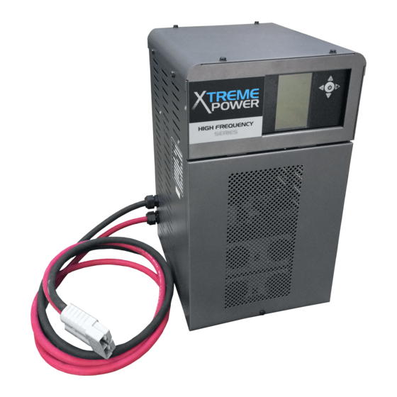
- Page 1 High Frequency Battery Charger Installation and Operation Manual...
- Page 2 FERRO MAGNETICS CORPORATION INDUSTRIAL CHARGER WARRANTY High Frequency Industrial Battery Chargers This Warranty Agreement entered between Ferro Magnetics Corporation, "Ferro", and the Original End User is with respect to Ferro Magnetics Corporation motive power battery charger product lines as stated above, for industrial electrical truck battery charging usage. 1.0 GENERAL: Ferro Magnetics Corporation (hereinafter called "Ferro") warrants that each new industrial battery charger supplied by it, is of good workmanship and is free from any inherent mechanical defects, provided: 1.1 The product is installed and operated in accordance with generally accepted industrial standards and in accordance with the printed instructions...
-
Page 3: Table Of Contents
INDEX Page Section Description Safety Instructions Installation Receiving Location Line Voltage AC Service Requirements Connecting AC Service to Charger Grounding the Charger Battery Connector and Charger Cable 7-13 Operation 046-0304 Control 11-12 Charge Indications Module LED Codes Troubleshooting & Maintenance Replaceable Parts Ordering Information Recommended Spares... -
Page 4: Safety Instructions
SAFETY INSTRUCTIONS WARNING THIS EQUIPMENT CONTAINS LETHAL VOLTAGE LEVELS. INSTALLATION AND SERVICING MUST BE PERFORMED BY QUALIFIED PERSONNEL IMPORTANT: SAVE THESE INSTRUCTIONS! READ AND FOLLOW ALL INSTRUCTIONS BEFORE INSTALLING, OPERATING, OR SERVICING CHARGER. ANY DEVIATION CAN CAUSE SERIOUS AND PERMANENT DAMAGE. -
Page 5: Line Voltage
SECTION 1 - INSTALLATION 1.1. Receiving Immediately upon receipt of the charger, check it against the shipping invoice to ensure the shipment is complete and undamaged. Examine the outside of the packing for signs of rough handling before accepting the charger from the carrier. -
Page 6: Ac Service Requirements
1.4. AC Service Requirements Follow local code requirements if they are different than the instructions in this manual. Refer to Table 1-1, to determine the correct ratings for the AC cable, AC fuses, and AC service disconnect switch for the line amperes as listed on the nameplate of the charger for the available AC voltage. -
Page 7: Control
SECTION 2 - OPERATION 2.1 DESCRIPTION The 046-0304 charger control provides fully automatic battery charging. The presence of a battery is detected by the control and causes a charge cycle to begin automatically. The control has charging profiles that handle standard flooded, gel-cell, and sealed lead-acid batteries, as well as other battery types such as nickel-cadmium and Li. - Page 8 46-304 Control Reference Guide 1. BATTERY HIGH TEMPERATURE INDICATOR 2. BATTERY LOW WATER INDICATOR 3. CHARGE STATE / CHARGE CYCLE MESSAGE TOBi 4. WI-Z COMMUNICATION INDICATOR 5. USB COMMUNICATTION INDICATOR 6. TOBI COMMUNICATION INDICATOR 7. HF MODULE HIGH TEMPERATURE INDICATOR 8.
- Page 9 OPERATION With no battery connected, the control displays ‘CONNECT BATTERY’ and the keypad will be flashing GREEN. When a battery is connected, a lamp test is performed. The charge then begins and the keypad will be flashing AMBER. The display show ‘CP1’ along with the charging amps. If equalize is active, an ‘=’ icon appears on the display to indicate an equalizing charge.
- Page 10 TOBI® PI OPERATION The control has the ability to communicate with a Tobi® PI battery module. For communication to occur, it must be enabled in the control. This is accomplished by setting the ‘BC’ parameter. Setting the BC parameter to 0 disables communication. Setting the BC parameter to 1 enables normal communication.
-
Page 11: Charge Indications
CHARGE INDICATIONS The following indications are not necessarily a result of a charger problem. They are typically caused by external problems such as AC line, poor battery conditions, connections, etc. If abnormal charge conditions are detected, the charge is terminated, the keypad will be solid RED and the display shows the code: DISPLAY DESCRIPTION POSSIBLE CAUSE... - Page 12 DISPLAY DESCRIPTION POSSIBLE CAUSE - Low AC Volts - Bad power supply M1 BIAS ERROR HF module bias error. - Bad HF Module - Battery disconnected while charging M2 HIGH DC - Wrong size battery (too many cells) HF module output DC volts high. VOLTS - Bad HF module - Wrong size battery (too few cells)
- Page 13 HF Module Switch and LED Locations Condition Possible Cause Module OK. Not Charging SOLID GREEN No Battery Connected Control Interface Cable Disconnected Module Charging BLINKING GREEN Normal Condition Output Over-Voltage BLINKING RED Battery Disconnected While Charging Wrong Size Battery (too many cells) Output Under-Voltage PULSING RED Wrong Size Battery (too few cells)
- Page 14 SECTION 3 – TROUBLESHOOTING & GENERAL MAINTENANCE Caution: There are lethal voltages exposed when the charger is energized with the door open. Always disconnect the AC service voltage to the charger before opening the door. The following chart lists the most probable cause of a malfunction. SYMPTOMS AND POSSIBLE CAUSES No charging current, the control has no display.
-
Page 15: Replaceable Parts
SECTION 4 – REPLACEABLE PARTS 4.1 Ordering Information The following information must be supplied when ordering a replacement part from your service agent to ensure that the correct part is supplied: A. Model or Spec. number of charger (Located on charger data plate) B.
Need help?
Do you have a question about the HIGH FREQUENCY Series and is the answer not in the manual?
Questions and answers
I need charging instruction on the Xtreme Power Model: XPT24-865, 48 volt industrial battery charger.