
Summary of Contents for LumaSense LumaSMART
- Page 1 LumaSMART ® Fiber Optic Winding Hot Spot Temperature Monitor and Controller for Power Transformers...
- Page 2 LumaSense Technologies prohibits the duplication of any portion of this manual or the use thereof for any purpose other than the operation or maintenance of the equipment described in this manual, without the express written permission of LumaSense Technologies or Advanced Energy Industries, Inc.
-
Page 3: Table Of Contents
Legend ............................9 Limit of Liability and Warranty ....................... 9 Unpacking and Inspection ......................10 Malfunction or Service Request ....................10 Shipments to LumaSense for Repair ..................... 10 Disposal / Decommissioning......................11 Introduction ............................13 System Overview .......................... 13 2.1.1 System Organization ...................... - Page 4 Installing the Tank Wall Adapter Plate ..................40 Installing the Tank Wall Plate Assembly ..................42 Installation of the LumaSMART ® Controller .................... 43 Mounting and Installing the LumaSMART Controller ..............44 4.1.1 Installing the Wall-Mount LumaSMART Controller ............... 44 4.1.2 Installing the Panel-Mount LumaSMART ................45 Installing the External Fiber Optic Extension Cable ...............
- Page 5 Setup Modbus ......................... 80 Setup IEC61850 over Ethernet TCP/IP ................80 Modbus Protocol Testing ........................81 Configuring Modbus Poll in LumaSMART over RS485 ..............81 Configuring the Modbus Poll program on a PC ................82 Testing Modbus Functions ......................83 6.3.1...
- Page 6 Modbus Input Register ......................96 IEC 61850 Protocol Testing ........................99 7.1.1 Test Setup..........................99 Configuring IEC 61850 in LumaSMART and TMW Hammer ............100 Connecting the LumaSMART and TMW Hammer ............... 102 Sample Relay Setup ........................103 Report Control ..........................105 IEC61580 Channel Temperature Alarm ..................
- Page 7 12 Appendix ............................. 145 12.1 Third Party Suppliers ........................145 12.2 List of Tables ..........................146 Index................................147 LumaSMART User Manual Contents • vii ®...
- Page 8 To ensure consistent document formatting, this page was intentionally left blank. LumaSMART User Manual Contents • viii ®...
-
Page 9: General
Software Upgrade Release Notes This software package is also being released as an upgrade for existing LumaSMART installations. Changes in the 4.1.0.4 release of software effect the operation of the communications protocols – Chapter 7 IEC61850, Chapter 8 DNP3, and Chapter 6 ModBus. -
Page 10: Unpacking And Inspection
Email: eusupport@lumasenseinc.com Shipments to LumaSense for Repair All RMA shipments of LumaSense Technologies instruments are to be prepaid and insured by way of preferred carrier. For overseas customers, ship units air-freight, priority one. The instrument must be shipped in the original packing container or its equivalent. LumaSense Technologies is not responsible for freight damage to instruments that are improperly packed. -
Page 11: Disposal / Decommissioning
Send RMA Shipments to your nearest technical service center: Santa Clara, California Frankfurt, Germany LumaSense Technologies, Inc. LumaSense Technologies GmbH 3301 Leonard Court Kleyerstr. 90 Santa Clara, CA 95054 USA 60326 Frankfurt Telephone: +1 408 727 1600 Germany +1 800 631 0176... - Page 12 To ensure consistent document formatting, this page was intentionally left blank. LumaSMART User Manual General • 12 ®...
-
Page 13: Introduction
2.1 System Overview LumaSMART is a fiber optic temperature sensing and control system specifically designed for direct winding temperature measurement and cooling control in high-voltage power transformers. Building on years of successful field-proven performance of the industry-standard LumaSense WTS-22 and ThermAsset systems, the LumaSMART system incorporates new features that improve ease of use, add capability, and reduce the cost of ownership. -
Page 14: System Organization
LumaSMART temperature measurement is based on the phosphorescence decay time of a special phosphor sensor, located at the end of a fiber optic cable. This specific sensor is basic to the LumaSMART function. The figure below illustrates temperature sensor construction. -
Page 15: Extracting Temperature From Phosphorescent Decay Time
LumaSMART’s flexible design enables sophisticated temperature control of the transformer without the need for additional instruments. One of the primary design features of the LumaSMART controller is reliability. The system utilizes all solid-state light sources, an LCD display, and a touch screen designed to withstand years of use. In addition, the controller can be wall or panel mounted or in a NEMA 4X enclosure. -
Page 16: Internal Components
Internal Components Access to the inside of the LumaSMART controller is rarely needed since all connections to the LumaSMART controller are made along the exterior surface. LumaSMART Controller Internal Components (Front Facing Upwards) Display The LCD is a VGA TFT display with integrated touch panel which allows both data display and data entry. The display has an LED backlight with user programmable intensity and time to wait before it dims. -
Page 17: Relay Module
Analog Output The LumaSMART controller has an analog output for each temperature channel on the external connectors for each FOT module. Each analog output is associated with a corresponding measurement channel (temperature probes). Analog outputs are labeled 1 to 16, where Analog Output 1 is associated with Channel 1;... -
Page 18: Front Features
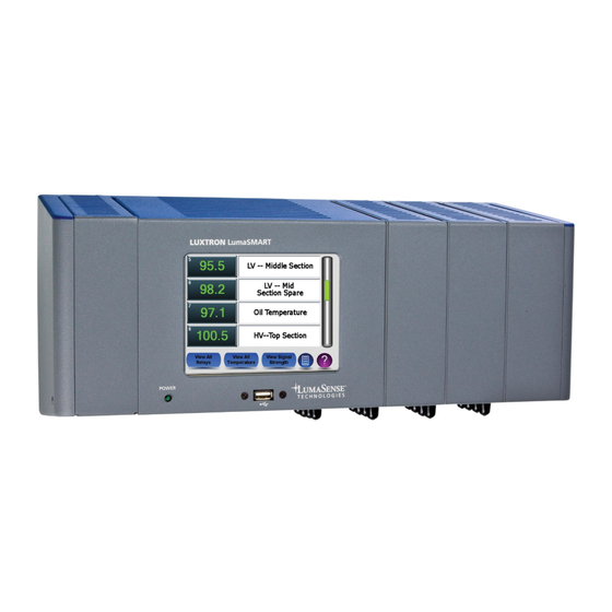
-30 °C and 20 mA corresponds to +200 °C. Analog Driver Output (Temperature versus Current) Front Features Under normal operating conditions, the LumaSMART controller case never needs to be opened. The front panel displays the temperatures being monitored, relay activation status, and system status. LumaSMART Controller Front View The figure below illustrates the components accessible from the LumaSMART controller’s front panel. -
Page 19: Back Features
LumaSMART. It can also be used to update the LumaSMART Software. Power LED The illuminated LED indicates power supplied to controller. Back Features The LumaSMART unit is mounted by screwing bolts through a wall/panel/plate. LumaSMART Controller Back View LumaSMART User Manual Introduction • 19... -
Page 20: Bottom Features
LumaSMART Module Back View Mounting Bottom Features Connections are made to the bottom of the LumaSMART unit. Since the LumaSMART controller can be configured with multiple modules, the connections are grouped by module. LumaSMART Controller with FOT and Relay Modules Bottom View (Front Facing Upwards) The number of connections a user will need to make will depend on the unit’s configuration (See... -
Page 21: Base Unit Relay Connections
LumaSMART Controller FOT Connections (Front Facing Upwards) Base Unit Relay Connections The Base Unit can house up to eight relays. The figure below shows the location and pin-out of these relay connections. It also shows the location and pin-out of the System Status Relay. -
Page 22: Base Unit Communications And Power Connections
The Base Unit has an access panel that allows the user to replace the battery when it wears out. It also allows the user to replace the flash drive where the system’s data log is stored. LumaSMART Controller Base Unit Access Panel (Front Facing Upwards) LumaSMART User Manual Introduction •... -
Page 23: Fot Module Connections
FOT Module Connections The LumaSMART controller can be configured with up to three additional FOT Modules, each housing two or four FOT channels. LumaSMART Controller FOT Module Connections (Front Facing Upwards) Control Module Connections The LumaSMART controller can also be configured with a Control Module which houses eight additional relays. -
Page 24: Operating Specifications
Operating Specifications Table 2: LumaSMART Controller Specifications Channels Number of Channels 4 to 16 (in increments of 2) Probes Accepts all LumaSense DipTip Rugged Probe and Quality Probe sensors Environmental Temperature Measurement Range -30 to +200 °C Temperature Accuracy ±2 °C Operating (Ambient) -30 to +70 °C... - Page 25 Analog Output: Phoenix Serial: Phoenix Ethernet: RJ45 Power: Phoenix Caution: Make sure to check the ID label on the LumaSmart unit to confirm that the input voltage type is correct (AC). Serial Interface Front Panel USB Port Status and Data Log Downloading...
-
Page 26: Configuration Options
A Tank Wall Plate (TWP) assembly is also available from LumaSense, and its carbon steel ring can be welded onto the transformer wall. The TWP assembly consists of a stainless steel feed-through plate, containing 4 to 24 welded- on tank wall penetrators, bolted to a carbon steel mounting ring. -
Page 27: Service Life
LumaSMART controller can be used to check the probes and fiber optic cables during installation. Service Life LumaSense probes are designed to survive in hot transformer oil for the life of the transformer. The LumaSMART controller electronics are designed to withstand the temperature, humidity, electromagnetically induced surges, and coupled noise pulses encountered in this field. -
Page 28: Increased Transformer Loading To The Safe Maximum
The LumaSMART controller unlocks additional MVA, which is quite valuable during routine and emergency situations. The key is to gain additional transmission capabilities without damaging the equipment. Precise winding hot spot measurements by the LumaSMART controller allows MVA loading to be maximized under operational or transient conditions. Conservatively, an additional 5 to 10% loading is available from a typical power transformer. -
Page 29: Installation Of Probes And Accessories
Caution: Only LumaSense DipTip Rugged Probe and Quality Probe Fluoroptic ® Probes should be used with the LumaSMART system. DO NOT attempt to attach other types of probes to the system. Caution: To prevent damage to the LumaSMART controller and/or components, diligently follow all instructions provided in this chapter. -
Page 30: Installation Philosophy
3.2 Installation Philosophy LumaSense has been a leader in the use of fiber optics to measure temperature in transformers for more than 25 years. During this time, LumaSense has continuously developed improved products and procedures to meet customer needs. This section provides general guidelines to help determine where and how the measuring device (FOT probes) should be installed. -
Page 31: Fot Installation Guidelines For Common Designs
Never use tie wraps to hold fiber cable in place. Cotton tape is preferred. The sample specification from LumaSense addresses most of the problem issues. 3.2.2 FOT Installation Guidelines for Common Designs The number of probes to be installed is dependent upon the information that the user desires and how the transformer is loaded. -
Page 32: Single Phase Transformers-Autotransformer And Gsu
If a probe connector end requires cleaning, wipe it with a cotton swab moistened with spectrograde methanol or ® isopropyl alcohol. Use the yellow Teflon cap to cover the connector ends when probes or extensions are not in use. LumaSMART User Manual Installation of Probes and Accessories • 32 ®... -
Page 33: Fiber Optic Cable Handling Precautions
• Pulling on the fiber optic cable to untangle twisted areas (carefully unwind any tangles) • Dropping or scraping the connectors on hard surfaces Fiber Optic Cable Handling Precautions LumaSMART User Manual Installation of Probes and Accessories • 33 ®... -
Page 34: Installing The Probes
Caution: Only LumaSense Quality and DipTip Rugged Fluoroptic Probes should be used with the LumaSMART system. DO NOT attempt to attach other types of probes to the system. The figure below illustrates the sensor location within the probe tip. For further details, refer to Section 2.2.1... -
Page 35: Sensor Installation Guidelines
The most secure method of positioning the sensor is to secure the fiber optic probe tip in a modified radial spacer. In this method, the probe tip lies in a cavity formed within the radial spacer. The tip measures the oil temperature LumaSMART User Manual Installation of Probes and Accessories •... -
Page 36: Radial Spacer Design
2 mm (0.08 in) thick TIV material (shown below). Modified Radial Spacer Note: Refer to Section 12.1 Third Party Suppliers for a list of suppliers that can provide materials used for modifying the radial spacer. LumaSMART User Manual Installation of Probes and Accessories • 36 ®... - Page 37 5. Laminate the second piece of COPACO paper or 1 mm (0.04 in) spacer to the remaining face of the modified spacer with adhesive (See figure at the top of the next page for final assembly). LumaSMART User Manual Installation of Probes and Accessories • 37...
-
Page 38: Installing Probe Tip In A Shell Form Transformer
2. For best response, tape the sensor “side-on” (the side of the probe is directly against the winding surface). The figure below illustrates a possible probe-tip mount. Probe Tip Installation— Shell Form LumaSMART User Manual Installation of Probes and Accessories • 38... -
Page 39: Alternate Probe Tip Installation Methods
6. Test the probes during each major step— phase assembly, core stacking, tanking, and fitting— by connecting to a LumaSMART controller. This raises awareness of protecting the fiber optic probes during each step. (The LumaSense 812 Portable Monitor can be used for this process (Refer to Section 2.3.3... -
Page 40: Probe Routing Inside The Transformer
The adapter plate accommodates four to sixteen fiber optic cables and is supplied with caps to protect the threads of unused channels. Caution: To plug unused channels preventing oil leakage, use LumaSense Internal and External tank wall plugs. LumaSMART User Manual Installation of Probes and Accessories •... - Page 41 Sample NEMA 12 Box Enclosure for Tank Wall Plate Assembly (Optional) The adapter plate and NEMA-box enclosure kit, as well as the Tank Wall Plate Assembly are available for purchase from LumaSense. Contact support@lumasenseinc.com for more information. LumaSMART User Manual Installation of Probes and Accessories •...
-
Page 42: Installing The Tank Wall Plate Assembly
3. Tighten the lock nut against the TWP assembly. Using a torque wrench, tighten one-half turn past hand- tight. Apply less than 25 foot pounds of torque. 4. Check the probe signal level with the LumaSMART controller to ensure the probe is properly installed. Signal level should be between 60% and 95%. (Refer to Section 4.5 Testing the Probe Signal Strength.) -
Page 43: Installation Of The Lumasmart Controller
• Has an Ethernet port, a RS485/RS232c and a USB port. Communication protocols include ASCII, IEC 61850, Modbus and DNP 3.0. The USB port can be used to download the data log or to upgrade the LumaSMART firmware. •... -
Page 44: Mounting And Installing The Lumasmart Controller
2. The wall-mount version of the LumaSMART includes four universal mounting brackets. Mark the holes for drilling. 3. Drill using an 8 mm (5/16 in) drill bit or tap the four holes in the wall upon which the LumaSMART is to be mounted, matching the hole pattern drawing included with your system. -
Page 45: Installing The Panel-Mount Lumasmart
2. The panel-mount version of the LumaSMART includes four universal mounting brackets. Mark the holes for drilling. 3. Drill using an 8 mm (5/16 in) drill bit or tap the four holes in the wall upon which the LumaSMART is to be mounted, matching the hole pattern drawing included with your system. -
Page 46: Installing The External Fiber Optic Extension Cable
Panel-Mount LumaSMART (Front View) 4.2 Installing the External Fiber Optic Extension Cable The exterior fiber optic extension cable connects between the tank wall penetrator and the LumaSMART controller. External fiber optic cables are available in a single or bundled (4) configuration. -
Page 47: Installing The Electrical Wiring
2. Tape the pull wire to at least 152.5 mm (6 in) of the outside fiber optic cable and then pull the fiber optic cable through the conduit. (Add conduit diameter). 3. Label and connect all cables through the bottom of the LumaSMART controller. Fiber Optic probe channels start from back to front (Channel 1 through Channel 4). -
Page 48: Power Wiring
4.3.1 Power Wiring The LumaSMART controller accepts nominal power of 90 to 264 VAC or 127 to 370 VDC, 47 to 63 Hz. The internal power supply generates 5 VDC. Caution: To protect the instrument, do not operate the LumaSMART above the factory default voltage levels. -
Page 49: Current Loop Considerations
Current Loop Considerations The LumaSMART provides surge protected isolated current sources for remote monitoring of temperature (including providing loop power). However, the isolation is not intended to withstand continuous offset voltages between the Loop Transmitter and Loop Receiver of greater than 20 volts. The recommended limit is 15 volts. -
Page 50: Relay Output Wiring
4.3.3 Relay Output Wiring The LumaSMART includes 0, 8, or 16 programmable Form-C relays and one system status Form-C relay. Use the MC 1.5/8-SFT-3.81 connector from Phoenix Contact (Part # 1827716) to make the external connection to the relay connectors. The optional ferrule is Part # 3200519. -
Page 51: Optional Communication Wiring
Data Manager and Chapter 10 User Commands. Note: Always connect the GND pin between the LumaSMART and the report communications device. Communication Wiring Diagram Use the MC 1.5/8-SFT-3.81 connector from Phoenix Contact (Part # 1827732) to make the external connection to the communication port. -
Page 52: Starting Up The Instrument
4.5 Testing the Probe Signal Strength To test the probe signal strength: 1. From the Home (Channels) screen of the LumaSMART touchscreen interface, press the View Signal Strength button. 2. A list of all channels and their probe signal strengths will be displayed. -
Page 53: Using The Software
The View All Relays screen contains a scrollable list of all relays and their current status. A Disabled status means that the relay must be activated and configured via the Setup menu. See Section 5.2.1.4 for Relay Setup. LumaSMART User Manual Using the Software • 53 ®... -
Page 54: Viewing All Temperatures
When a probe is properly connected and not in an alarm state, it will display its current temperature reading. 5.1.3 Viewing Signal Strength The Sensor Channel Diagnostics screen contains a scrollable list of all channels and their current signal strengths. Sensor Channel Diagnostics Screen LumaSMART User Manual Using the Software • 54 ®... -
Page 55: Main Menu
5.2 Main Menu The Main Menu contains buttons leading to all of the main functions and configuration options of the LumaSMART ® controller. Main Menu Note: To return to this screen at any time, click the Main Menu button: •... - Page 56 Analog Outputs—Allows you to configure analog output settings for each channel, such as the output current limit, current range and temperature range. • Channel Setup—Allows you to enable/disable each channel and set its name. To enter the authentication code: Enter Setup Authentication Code LumaSMART User Manual Using the Software • 56 ®...
-
Page 57: Transformer Info Setup
For instructions on changing the authentication code, refer to Section 5.2.1.3 Administrator Tools. If you lose your authentication code, contact LumaSense technical support at +1 408 727 1600 or support@lumasenseinc.com. Transformer Info Setup The Transformer Info screen allows you to input the details of your transformer, including: •... -
Page 58: Date & Time
The Administrator Setup screen allows you to make important updates to your software by changing the authentication codes or applying a firmware upgrade. An authentication code is required to access this screen. Administrative Setup Screen LumaSMART User Manual Using the Software • 58... -
Page 59: Download Firmware
The following procedure provides information on updating firmware retrieved from a USB thumb drive. Note: The thumb drive should be supplied from LumaSense. Using a non-approved thumb drive can allow viruses to infect the LumaSmart. ALWAYS scan the thumb drive on a PC with an up-to-date anti-virus utility before proceeding. - Page 60 6. Verify the settings for the specific model configuration of the LumaSMART and press Next. Shown below • 16 Channel (4 FOT @ 4 Channels each) • 16 Relay (2 Relay cards @ 8 Relays each) • 4-20mA/0-1mA Configuration of the installed FOT’s •...
-
Page 61: Change Authentication Code
The Export / Import configuration screen allows you to export and import the system’s configuration file. This file contains the information as to how the user has configured the LumaSMART. It is also useful for diagnosing setup problems. To use this feature, you must insert a USB thumb drive before pressing the button. -
Page 62: Stop Watchdog For 5 Minutes
Relay Tests This is a service function used to exercise the relay operations. This test should not be used when the LumaSMART is controlling critical functions with its relays. When pressed, a warning will appear: Pressing No will abort the test and if Yes is pressed, the following will occur: 1. -
Page 63: Status System Relay
30 days of power loss. Note: If the LumaSMART controller undergoes a power cycle (outage) after the battery is depleted, the system date will revert to year 2003 and the Date/Time stamps in all system log and status files will reflect the incorrect date. - Page 64 Figure: Form-C Relay in Deenergized (Off) State). This is the failsafe mode 4.3.3 Relay Output Wiring wherein a power outage of the LumaSmart causes the relay to act as if the Alarm Condition is met Figure: Form-C Relay in Deenergized (Off) State). (See Section 4.3.3 Relay Output Wiring •...
-
Page 65: Analog Outputs
Analog Outputs The Analog Outputs overview screen shows a list of the channels and their current analog output configurations. The analog output configuration was set during the manufacture phase and cannot be changed. LumaSMART User Manual Using the Software • 65... - Page 66 Min and Max number boxes. The minimum temperature you can select is -30 ºC and the maximum is 200 ºC. The Min and Max currents are the same as the highlighted green indicator at the top of the screen. LumaSMART User Manual Using the Software •...
-
Page 67: Channel Setup
5.2.2 Transformer Info The Transformer Info screen displays the details of your transformer, including name, type, and year of manufacture. See Section 5.2.1.1 Transformer Info Setup to set up or edit transformation information. LumaSMART User Manual Using the Software • 67 ®... -
Page 68: Battery Life
If you find that the date and time in the menu screen is incorrect, it means that a power outage has occurred and the battery is depleted. Go to Menu < Setup < Date & Time to set time and date and replace the battery. LumaSMART User Manual Using the Software •... -
Page 69: Display
The Data Log Export screen allows you to export a specific date range of data log reports to a USB thumb drive. Data Log Export To provide easy selection of the desired date range, five predefined date range buttons are supplied to set the range relative to “today”. LumaSMART User Manual Using the Software • 69 ®... - Page 70 </Time> </Date> The Channel and Relay entries are made at 1 minute intervals. The SignalStrength entries are added once an hour. The exported folder DataLogRaw can be ignored. It contains information used by LumaSense service personnel. LumaSMART User Manual Using the Software • 70...
-
Page 71: Diagnostics
5.2.6 Diagnostics The Diagnostic menu provides access to tools to monitor, analyze and test operational characteristics of the LumaSMART, which include: • Sensor Channel Diagnostics See Section 5.2.6.1 for of the probe signal strength. • See Section 5.2.6.2 for Relay Testing Simulation to allow testing of the control logic established in the Relay Setup (see Section 5.2.1.4). -
Page 72: Relay Testing/Simulation
Erase Data Log This function allows the operator to erase history logs within the LumaSMART. Since the internal storage has enough room to store more than 40 years of daily temperature history, there should never be a need to use this function. -
Page 73: File Viewer
System Status Viewer The entry following SN: is the serial number. The entry following SV: is the Software Version of the LumaSMART. If the SN: entry says “Not Set”, see Setup > Administrative Tools > Serial Number to enter the Serial Number of this system. -
Page 74: System Status Relay History
Configuration The LumaSmart controller maintains an .xml encoded file that contains all of the customizable configuration information of the LumaSMART. This selection allows the contents to be viewed and the file exported. You can use Export/Import Configuration File (see Section 5.2.1.3) feature to back up a configuration file and also import a modified version. - Page 75 Note: A temperature value of zero (0) is displayed when no data for a probe is available. This includes time when power is removed from the LumaSMART or a channel was not functioning properly. In the above graph, the LumaSMART was turned off until about 7AM.
-
Page 76: Data Graph Zoom Feature
25 hours. The graphing utility is licensed under the GNU Lesser Public Licensing from ZedGraph Class Library - A Flexible Line Graph/Bar Graph Library in C# Copyright © 2007 LumaSMART User Manual Using the Software • 76... -
Page 77: Communication And Protocols
Note: Only 1 selectable Protocol can be activated and attached to 1 of the electrical interfaces. Select Interface The following is a sample display associated with using the RS485 interface: Sample RS485 Selection LumaSMART User Manual Using the Software • 77 ®... -
Page 78: Setup Rs485 Interface Parameters
Port Number (1 to 65535) • IP Address Standard IPv4 address, subnet mask and default Gateway To set these values, press the IP Address EDIT key. The following screen will be displayed. LumaSMART User Manual Using the Software • 78 ®... -
Page 79: Setup Dnp3
Note: If TCP/IP is being used for DNP 3.0, Modbus or IEC61850, please make sure that the ID is added or changed for different devices. Make sure that the equipment in the network routes between the LumaSMART and monitoring computer are properly configured. -
Page 80: Setup Modbus
6. If the Interface is TCP/IP, Edit the Master IP Address to match the IP address of the computer which will be communicating with the LumaSMART. 7. When all of the displayed values are as desired, press Save to store. -
Page 81: Modbus Protocol Testing
00-15229-216 LumaSMART, 16 Channels, 16 relay, 4...20 mA analog output If your LumaSMART is of a different configuration, then the Modbus Poll configuration will need to be modified to limit the register access to the bounds of the LumaSMART you are using. (Number of Temperature channels, relays, etc…) Please refer to the Modbus Poll program instructions manual for instruction on changing the... -
Page 82: Configuring The Modbus Poll Program On A Pc
1. Open the Modbus Poll software. 2. Click on File -> Open WorkSpace 3. Select and load the file: LSresumeAll.mbw 4. A screen similar to the following should appear: Modbus Poll screen LumaSMART User Manual Modbus Protocol Testing • 82 ®... -
Page 83: Testing Modbus Functions
Wiring. As shown above, all relays are Deenergized except the System Status Relay, which Energized when no system error is occurring. The coil status is read-only since control of the state is based on the user configuration. LumaSMART User Manual Modbus Protocol Testing • 83... -
Page 84: Read Discrete Input Status (0X02)
These values are read-only since they are based on the manufacturing configuration/model of the LumaSMART. 6.3.3 Holding Registers (0x03, 0x06, 0x16) This function is used to read and write different parameters regarding the configuration of the LumaSMART. They are categorized as follows: 1. - Page 85 4. Monitoring/Control of Temperature Probe Enable/Disable. All channels are represented in a single 16 bit mapped field. Channel Setup LumaSMART User Manual Modbus Protocol Testing • 85 ®...
-
Page 86: Input Registers (0X04)
1. Temperature Reading and Signal Strength level. These are grouped in sets of 2 entries for each channel. Viewing Temperature and Signal Strength 2. The Build Configuration can be read: Build configuration view LumaSMART User Manual Modbus Protocol Testing • 86 ®... -
Page 87: Sample Relay Setup Over Modbus
The general format of the edit window that displays is: Edit Window In this example, register address 84 was selected, which is Relay 5 Config. LumaSMART User Manual Modbus Protocol Testing • 87 ®... - Page 88 Checking the registers for Relay 5 shows that the desired values are stored. You can also verify by reviewing the LumaSMART relay setup screen: Relay Setup screen Given the Ref Temp of 36+ °C, the relay should Energize.
-
Page 89: Modbus Register Map
Status for Relay 15 Binary Bool 1 = Energized 0 = Deenergized Status for Relay 16 Binary Bool 1 = Energized 0 = Deenergized 17-63 Reserved for future expansion Binary Bool LumaSMART User Manual Modbus Protocol Testing • 89 ®... -
Page 90: Modbus Input Status
Int16 Minimum Temperature Analog Output FOT 3 Int16 Minimum Current Analog Output FOT 3 Int16 Maximum Current Analog Output FOT 3 Int16 Minimum Temperature Analog Output FOT 3 Int16 Minimum Temperature LumaSMART User Manual Modbus Protocol Testing • 90 ®... - Page 91 Restore Set Point for Relay 2 Int16 Channels Driving Relay 2 Int16 MSB = CH16 / LSB = CH1 Bit Mapped Control Setting for Relay Number 2 2 = OR Logic Int16 1 = AVG Logic LumaSMART User Manual Modbus Protocol Testing • 91 ®...
- Page 92 Restore Set Point for Relay 5 Int16 Channels Driving Relay 5 Int16 MSB = CH16 / LSB = CH1 Bit Mapped Control Setting for Relay Number 5 2 = OR Logic Int16 1 = AVG Logic LumaSMART User Manual Modbus Protocol Testing • 92 ®...
- Page 93 Restore Set Point for Relay 8 Int16 Channels Driving Relay 8 Int16 MSB = CH16 / LSB = CH1 Bit Mapped Control Setting for Relay Number 8 2 = OR Logic Int16 1 = AVG Logic LumaSMART User Manual Modbus Protocol Testing • 93 ®...
- Page 94 Restore Set Point for Relay 11 Int16 Channels Driving Relay 11 Int16 MSB = CH16 / LSB = CH1 Bit Mapped Control Setting for Relay Number 11 2 = OR Logic Int16 1 = AVG Logic LumaSMART User Manual Modbus Protocol Testing • 94 ®...
- Page 95 Restore Set Point for Relay 14 Int16 Channels Driving Relay 14 Int16 MSB = CH16 / LSB = CH1 Bit Mapped Control Setting for Relay Number 14 2 = OR Logic Int16 1 = AVG Logic LumaSMART User Manual Modbus Protocol Testing • 95 ®...
-
Page 96: Modbus Input Register
CD AB Float Probe Signal Strength Channel 1 CD AB Float 4 - 5 Temperature of Channel 2 CD AB Float 6 - 7 Probe Signal Strength Channel 2 CD AB LumaSMART User Manual Modbus Protocol Testing • 96 ®... - Page 97 46 - 47 Probe Signal Strength Channel 12 CD AB Float 48 - 49 Temperature of Channel 13 CD AB Float 50 - 51 Probe Signal Strength Channel 13 CD AB LumaSMART User Manual Modbus Protocol Testing • 97 ®...
- Page 98 Number of Relays present AB CD Float 132 - 133 Software Version (Major) CD AB Float 134 - 135 Software Version (Minor) CD AB 136 - 160 Reserved for future expansion LumaSMART User Manual Modbus Protocol Testing • 98 ®...
-
Page 99: Iec 61850 Protocol Testing
• Network Settings On the distribution CD of the LumaSMART is a folder that contains the configuration files for using the Hammer program which is pre-configured for communicating with the LumaSMART. The Hammer tool can also be configured by opening the LumaSmart.icd file also provided on the LumaSMART disk. -
Page 100: Configuring Iec 61850 In Lumasmart And Tmw Hammer
IEC 61850 Test Setup Note: Make sure that the LumaSMART system is properly running with the Ethernet Port Enabled. Also make sure that the PC (with the 61850 Test Harness Tool running) and the LumaSMART Device are present in the same network. - Page 101 For the TMW Hammer, the configuration screens are: TMW Hammer Test Setup Screen Note: The configurations between the two screens match. Furthermore, the TMW Hammer program is reading the LumaSmart.icd file rather than using the discovery mechanism. LumaSMART User Manual IEC 61850 Protocol Testing •...
-
Page 102: Connecting The Lumasmart And Tmw Hammer
7.3 Connecting the LumaSMART and TMW Hammer If the Status bar is a Red Color, then it indicates that the tool is not able to communicate with the LumaSMART device. If this is the case, you will need to reconfigure the settings to make sure that LumaSMART and TMW Hammer are configured to communicate, that you have the proper electrical connections, and the configuration/integrity of LAN network correct. -
Page 103: Sample Relay Setup
In this example, R4CSWI4 > RelCfg > ctlVal was selected, which is Relay 4 Config. A value of 1 (Normally Deenergized) is typed in, followed by return. After Refresh the display shows: LumaSMART User Manual IEC 61850 Protocol Testing • 103 ®... - Page 104 > Chn3Stat > ctlVal to ‘True’ (associate channel 3 with relay 4) R4CSWI4 > Chn4Stat > ctlVal to ‘True’ (associate channel 4 with relay 4) R4CSWI4 > Chn5Stat > ctlVal to ‘True’ (associate channel 5 with relay 4) LumaSMART User Manual IEC 61850 Protocol Testing • 104 ®...
-
Page 105: Report Control
R4CSWI4 > RefTemp > instMag > f Given the Ref Temp of 38+ degrees, the relay should Energize. This can be verified on the LumaSMART display and also through the 61850 interface as follows: R4CSWI4 > Pos > stVal is ‘on’ indicating energized. -
Page 106: Iec61580 Channel Temperature Alarm
The 61850 protocol allows you to set a unique temperature alarm for each channel and will notify the IEC61850 client whenever it changes states (Alarm/Restore). It does not affect operation of the LumaSMART and cannot be configured locally at the LumaSMART touchscreen. - Page 107 Reference Temperature) 2. Read the alarm status in LumaSMARTQ > CH5STMP5 > Alm > stVal (Value = False) Alarm Status This can be seen in the report: bcrbCHANTMPALRM bcrbCHANTMPALRM Report LumaSMART User Manual IEC 61850 Protocol Testing • 107 ®...
-
Page 108: Iec61850 Channel Signal Strength Alarm
The 61850 protocol also allows you to set a unique Signal Strength alarm for each channel. When it changes states, a notification is sent to the IEC61850 client (Alarm/Restore). It does not affect operation of the LumaSMART and cannot be configured locally at the LumaSMART touchscreen. -
Page 109: Iec61580 Register Maps
7.8 IEC61580 Register Maps Note: x is the Channel number: 1 > 16 (Max depend on LumaSmart configuration) 7.8.1 IEC61850 Temperature Channel Control and Supervision Table 10: IEC61850 Temperature Channel Control and Supervision ..CHxSTMPx Temperature Channel Supervision ..Mod Mode ..stVal... - Page 110 CHxSTMPx.SigStrnAlrm.stVal and ...i Present Probe Signal Strength therefore bcrbCHANTMPALRM ..ctlNum Present Probe Signal Strength Alarm Setpoint Note: IEC61850 only - Does NOT ..q Validity Good / Validity Invalid affect default LumaSmart SSR ..t operation ..ctlModel ..minVal ...i ..maxVal ...i ..SigStrnAlrm...
-
Page 111: Iec61850 Relay Channel Control And Supervision
..stVal ..q Validity Good / Validity Invalid ..t timestamp ..NamPlt Name Plate ..vendor LumaSense Technologies, Inc...swRev Note: Value can only be set locally at the ..d Relay Name description LumaSmart ..Pos Note: Also shown in report Present Status of the System Status ..stVal... -
Page 112: Iec61850 Fot Setup And Status Monitoring
Entry to Include (True) or Exclude (False) Relay ..stVal Present Inclusion status 7.8.3 IEC61850 FOT Setup and Status Monitoring Note: Max value depends on the LumaSMART configuration Table 12: IEC61850 FOT Setup and Status Monitoring ..FOTxCSWIx....Where x is the FOT number 1-> 4 ..Mod Mode ..stVal... -
Page 113: Iec61850 System Status Relay Report
Table 13: IEC61850 System Status Relay Report ..SSRCSWI0 System Status Relay Node ..Mod Mode ..stVal ..q Validity Good / Validity Invalid ..t ..ctlModel status-only ..Beh Behaviour ..stVal ..q Validity Good / Validity Invalid ..t LumaSMART User Manual IEC 61850 Protocol Testing • 113 ®... -
Page 114: Iec61850 General System Configuration Information
..Health Channel Health ..stVal ..q Validity Good / Validity Invalid ..t ..NamPlt Name Plate ..vendor LumaSense Technologies, Inc...swRev ..d System Status Relay ..Pos Position Note: Also shown in report Present Status of the the Relay ..stVal (Position) bcrbRELAYSTAT.SSRCSWI0.Pos.stVal ..q Validity Good / Validity Invalid ..t... -
Page 115: Iec61850 Report Contents - Temperatures And Relays
Number of FOT's in the LumaSmart Note: Depends on model, value is 1->4 ..q ..t ..ctlModel status-only ..Relays ..stVal Number of Relays in the LumaSMART Note: Depends on model, value is 1->17 ..q ..t ..ctlModel status-only ..Version LumaSmart Software Revision ..stVal Number Note: Form is W.X.Y.Z... -
Page 116: Iec61850 Reports Channel Temperature And Probe Signal Strength Alarms
Table 17: IEC61850 Probe Signal Strength levels Channel Probe Signal Strength LLN0.Report Control.ucrbPROBESIGSTRN (%) CH1STMP1.SigStrnAlrmSetPt.mxVal.i CH2STMP2.SigStrnAlrmSetPt.mxVal.i CH3STMP3.SigStrnAlrmSetPt.mxVal.i CH4STMP4.SigStrnAlrmSetPt.mxVal.i CH5STMP5.SigStrnAlrmSetPt.mxVal.i CH6STMP6.SigStrnAlrmSetPt.mxVal.i CH7STMP7.SigStrnAlrmSetPt.mxVal.i CH8STMP8.SigStrnAlrmSetPt.mxVal.i CH9STMP9.SigStrnAlrmSetPt.mxVal.i CH10STMP10.SigStrnAlrmSetPt.mxVal.i CH11STMP11.SigStrnAlrmSetPt.mxVal.i CH12STMP12.SigStrnAlrmSetPt.mxVal.i CH13STMP13.SigStrnAlrmSetPt.mxVal.i CH14STMP14.SigStrnAlrmSetPt.mxVal.i CH15STMP15.SigStrnAlrmSetPt.mxVal.i CH16STMP16.SigStrnAlrmSetPt.mxVal.i LumaSMART User Manual IEC 61850 Protocol Testing • 116 ®... -
Page 117: Dnp3 Protocol Testing
00-15229-216 LumaSMART, 16 Channels, 16 relay, 4...20 mA analog output If your LumaSMART is of a different configuration, then the test configuration will have to be modified to limit the register access to the bounds of the LumaSMART you are using. (Number of Temperature channels, relays, etc…) Please refer to the Protocol Test Harness program instructions manual. -
Page 118: Configuring Dnp3 In Lumasmart (Ethernet Tcp/Ip)
8.1 Configuring DNP3 in LumaSMART (Ethernet TCP/IP) 1. Press Menu > Diagnostic > Communication & Protocols. 2. Enter your password when prompted. 3. Setup of the communication interface and protocol combinations as shown below: Communications and Protocol Setup 4. Launch the Test Harness software. To establish a connection, the configuration screens should be:... -
Page 119: Testing Harness Window Components
Note: You will need to adjust the values for the IP addresses to match those within the specific test environment. Note: To perform this test using the RS485 interface, you will need to reconfigure the LumaSMART and Test Harness program to use the RS485 interface. The results would be the same. - Page 120 DNP3 Command Selection Window The following screenshot shows the data window and is used to view the data from the LumaSMART. The upper left box is used to select what classification of data is to be shown in the bigger right side box. This window is static and does not automatically refresh unless Unsolicited Reports are selected as ‘ON’...
-
Page 121: Dnp3 Enable Unsolicited Reports
To simplify this test, the unsolicited reports will be enabled. This will allow the data window to refresh automatically without having to invoke a status Integrity Data Poll after each LumaSMART configuration change. Select the Enable/Disable Unsolicited Messages command and press Once. -
Page 122: Binary Outputs
Reference the DNP3 mapping at the end of the section. The information includes: • Numbers 0 ⇒ 4 are system configuration associated with the capabilities of the LumaSMART model. • Number 5 is the System Status Relay state. On is the default non-alarm state. - Page 123 Here all shown as 1 (Enabled). For systems that do not have 16 channels, the associated Flag will indicate Offline. To Enable/Disable a channel: 1. Run the Control Relay Output Block command. Control Relay Output Block screen LumaSMART User Manual DNP3 Protocol Testing • 123 ®...
-
Page 124: Analog Inputs
5. Press Once. 6. Verify that the desired Relay changed in the Data View window: 7. Check the LumaSMART display. It should show channel 4 as disabled: LumaSMART display 8. Set the Control Code to lon and press once to re-enable the channel. - Page 125 Number 33 indicates the number of relays in the system. (1 System Status Relay + 16 General Control Relays) • Number 34 represents the firmware revision of the LumaSMART. 3230 is version 3.2.3.0 Note: In this example, Channel 4 was disabled and therefore shows 999 as the temperature, 0 as its Signal Strength, and Flagged as Offline.
-
Page 126: Analog Output Statuses
Analog Output section of this manual for more information. The entries for each group, in order, are: • Minimum Output Current • Maximum Output Current • Minimum Temperature representing the Minimum Output Current • Maximum Temperature representing the Maximum Output Current LumaSMART User Manual DNP3 Protocol Testing • 126 ®... - Page 127 2. Point Number 5, Value 19, Once 3. Point Number 6, Value -20, Once 4. Point Number 7, Value 200, Once The new values in the Data Window should reflect the changes as: Data Window displaying changes LumaSMART User Manual DNP3 Protocol Testing • 127 ®...
-
Page 128: Configuring Relay Operation
View the LumaSMART screen for this parameter to review the change: LumaSMART Analog Output Channel screen 8.7.2 Configuring Relay Operation The follow shows default entries for the Relay Control variables. This is not the complete list since the full list is 80 entries long. - Page 129 3. Set the Point Number to the desired value to change (see Section 8.8 DNP3 Resister Map). 4. Set the Variation to Short. 5. Set the Value to the desired value. 6. Press Once. LumaSMART User Manual DNP3 Protocol Testing • 129 ®...
- Page 130 The new values in the Data Window should reflect the changes as: Data Window reflecting changes View the LumaSMART screen for this parameter to review the change: LumaSMART Relay Setup screen Since the Ref Temp is greater than the Alarm Setpoint Temperature, the relay should be Energized. Checking the...
-
Page 131: Dnp3 Register Map
1 = Enable 0 = Disable Bool Binary Status for Channel Number 15 Bool 1 = Enable 0 = Disable Binary Status for Channel Number 16 Bool 1 = Enable 0 = Disable LumaSMART User Manual DNP3 Protocol Testing • 131 ®... -
Page 132: Dnp 3 Binary Input Map
0 = Deenergized (Off) Status for Relay 9 Binary 1 = Energized (On) Bool 0 = Deenergized (Off) Status for Relay 10 Binary 1 = Energized (On) Bool 0 = Deenergized (Off) LumaSMART User Manual DNP3 Protocol Testing • 132 ®... -
Page 133: Dnp 3 Analog Output Map
Int32 Maximum Temperature Analog Output FOT 3 Uint32 Minimum Current Analog Output FOT 3 Uint32 Maximum Current Analog Output FOT 3 Int32 Minimum Temperature Analog Output FOT 3 Int32 Maximum Temperature LumaSMART User Manual DNP3 Protocol Testing • 133 ®... - Page 134 Logic for Relay 4 Uint32 2 = OR … 1 = AVG ... 0=None Channel Temperature Inputs for Relay 4 Uint32 Bit Mapped (Bit 15 = Channel 16 … Bit 0 = Channel 1) LumaSMART User Manual DNP3 Protocol Testing • 134 ®...
- Page 135 Logic for Relay 9 Uint32 2 = OR … 1 = AVG ... 0=None Channel Temperature Inputs for Relay 9 Uint32 Bit Mapped (Bit 15 = Channel 16 … Bit 0 = Channel 1) LumaSMART User Manual DNP3 Protocol Testing • 135 ®...
- Page 136 Logic for Relay 14 Uint32 2 = OR … 1 = AVG ... 0=None Channel Temperature Inputs for Relay 14 Uint32 Bit Mapped (Bit 15 = Channel 16 … Bit 0 = Channel 1) LumaSMART User Manual DNP3 Protocol Testing • 136 ®...
-
Page 137: Dnp 3 Analog Input Map
Float Signal Strength for Channel 9 Float Temperature value for Channel 10 Float Signal Strength for Channel 10 Float Temperature value for Channel 11 Float Signal Strength for Channel 11 Float LumaSMART User Manual DNP3 Protocol Testing • 137 ®... - Page 138 Float Temperature value for Channel 16 Float Signal Strength for Channel 16 Float Number of FOT devices present in system Uint32 Number of relays present in system Uint32 Software Version Float LumaSMART User Manual DNP3 Protocol Testing • 138 ®...
-
Page 139: Data Manager
To permanently save data reports, export them from the LumaSMART controller through the interface port or by exporting them onto a thumb drive via the USB port (See Section 5.2.5, Data Log Export, for more information on exporting via USB). -
Page 140: Operation During Data Retrieval Mode
Data Manager always sends the oldest data report first • The LumaSMART controller ignores user commands • The LumaSMART controller does not send real-time 10 second data reports. However, it still saves the reports to the database • Host commands are inactive •... -
Page 141: User Commands
LumaSMART ® Some LumaSMART operations can be performed with a standard laptop computer with an RS232 port: 1. Connect a standard RS232 serial cable between the laptop computer’s COM1 or COM2 port and the LumaSMART’s RS232 port (found on the bottom of the controller). -
Page 142: Rtrv Command
10.2 rtrv Command The command rtrv=X retrieves X number of days of Data Log reports the LumaSMART. If the memory is empty, the Data Manager replies Okay, and no data reports follow. If the requested number of data reports is greater than the number of reports in memory, the Data Manager sends the available number of reports. -
Page 143: Maintenance
Do not use liquids or allow anything to enter the top vents. Warning: The top vents of the LumaSMART system allow access to hazardous live parts inside the device. Exercise caution when working near the vents. - Page 144 Caution: Use rubber gloves or other protection when handling the new battery, as finger prints can reduce the battery’s life span. 5. Replace all panels and cables, and bring the system back online. 6. Using the touchscreen, navigate to the Battery Life software screen and press Reset. LumaSMART User Manual Maintenance • 144 ®...
-
Page 145: Appendix
12 Appendix 12.1 Third Party Suppliers This appendix provides a list of suppliers of third-party products used with the LumaSMART ® Name Products Phone/Fax Address/URL Cottrell Paper COPACO Paper +1-518-885-1702 PO Box 35 Company Rock City Falls, NY 12863 USA +1-518-885-0741 (Fax) www.cottrellpaper.com... -
Page 146: List Of Tables
12.2 List of Tables Table 1: LumaSMART Controller External Components and Functions ............... 19 Table 2: LumaSMART Controller Specifications ......................24 Table 3: LumaSMART Controller Configuration Options ..................... 26 Table 4: Installation Work Hours and Equipment......................44 Table 5: LumaSMART Standard Configuration ......................47 Table 6: Modbus Coil Status ............................ -
Page 147: Index
FOT Modules 15 Communication Connections 15, 51, 71 Configuration Options 15, 47 Configuring DNP3 in LumaSMART 118 Configuring IEC 61850 in LumaSMART 100 IEC 61850 Protocol Testing 99 Configuring Modbus in LumaSMART 81, 82 Installation of Probes and Accessories 29... - Page 148 Relay & Control 55 Modbus Protocol Testing 81 Transformer Info Setup 55 Modbus Register Map 89 Temperatures Screen 54 Mounting and Installing the LumaSMART Controller Transformer Info 67 Software Administrator Tools 55 Administrator Setup 55 Change Authentication Code 55 Download Firmware 55...
Need help?
Do you have a question about the LumaSMART and is the answer not in the manual?
Questions and answers