Table of Contents
Advertisement
Quick Links
Advertisement
Table of Contents

Summary of Contents for REXROTH efc series
- Page 1 Frequency Converter Multi-Ethernet Card Instruction Manual Edition 02 R912006860...
- Page 2 This document, as well as the data, specifications and other information set forth in it, are the exclusive property of Bosch Rexroth (Xi'an) Electric Drives and Controls Co., Ltd. It may not be reproduced or given to third parties without its consent.
-
Page 3: Table Of Contents
Multi-Ethernet Card Bosch Rexroth AG Table of Contents Table of Contents Page Safety Instruction.................. Introduction................... 2 About This Documentation..............Engineering Tools................... 3 Reference Documentations..............4 Hardware Installation................5 Hardware Description................5 Installing the Card in Frequency Converter........... Cables....................6 LEDs....................... 7 Power Supply.................. - Page 4 Bosch Rexroth AG Multi-Ethernet Card Table of Contents Page Protocol Configuration................. 22 System Configuration................6.2.1 EDS File....................6.2.2 Generic Device..................23 6.2.3 Topology....................6.2.4 Process Data Configuration..............23 Acyclic Communication................ 28 6.3.1 Message Parameters................28 6.3.2 Error Codes..................29 Example....................
- Page 5 Multi-Ethernet Card Bosch Rexroth AG Table of Contents Page 10.2.2 Parameter List..................Diagnosis..................... 11.1 LED Indications..................54 11.2 Warning Code..................11.3 Error Code................... DOK-RCON0*-XFCX610*MUL -IT02-EN-P...
- Page 6 Bosch Rexroth AG Multi-Ethernet Card DOK-RCON0*-XFCX610*MUL -IT02-EN-P...
-
Page 7: Safety Instruction
Read and understand these safety instructions and all user documentation prior to working with these components. If you do not have the user documenta- tion for the components, contact your responsible Bosch Rexroth sales partner. 1/61 DOK-RCON0*-XFCX610*MUL -IT02-EN-P... -
Page 8: Introduction
Bosch Rexroth AG Multi-Ethernet Card Introduction 2 Introduction 2.1 About This Documentation This documentation contains necessary data and information descriptions rela- ted to the Multi-Ethernet Platform (MEP) extension card, which is one of the fieldbus communication module accessories of EFC x610 series frequency con- verter. -
Page 9: Engineering Tools
2.2 Engineering Tools For using the MEP extension card, an engineering connection from laptop / PC to the EFC series frequency converter is necessary. Such a connection can be established with using following methods: Via Ethernet using IndraWorks. In this case, the MEP can be browsed and the ●... -
Page 10: Reference Documentations
Bosch Rexroth AG Multi-Ethernet Card Introduction 2.3 Reference Documentations Type Typecode Language Material Number DOK-RCON03-EFC-x610***-ITRS-ZH-P Chinese R912005853 Operating Instructions DOK-RCON03-EFC-x610***-ITRS-EN-P English R912005854 DOK-RCON03-EFC-x610***-QURS-ZH-P Chinese R912005855 Quick Start Guide DOK-RCON03-EFC-x610***-QURS-EN-P English R912005856 Instruction Manual (UL) DOK-RCON01-REX*F*UL***-INRS-EN-P English R912004711 DOK-RCON0*-XFC-X610***-ASRS-EN-P English R912006261... -
Page 11: Hardware Installation
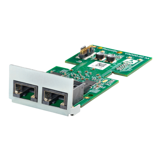
Multi-Ethernet Card Bosch Rexroth AG Hardware Installation 3 Hardware Installation 3.1 Hardware Description Fig. 3-1: Hardware illustration The MEP extension card is provided with two shielded female RJ45 connectors. 5/61 DOK-RCON0*-XFCX610*MUL -IT02-EN-P... -
Page 12: Installing The Card In Frequency Converter
Bosch Rexroth AG Multi-Ethernet Card Hardware Installation 3.2 Installing the Card in Frequency Converter The MEP extension card must be installed in combination with the extension card module in the EFCx610 frequency converter. For details, please refer to Ex- tension Card Module Mounting Instructions. -
Page 13: Leds
Multi-Ethernet Card Bosch Rexroth AG Hardware Installation 3.4 LEDs Two slots are provided in the extension card module. On each slot, four dual-col- or LEDs are equipped for state indication if the MEP extension card is applied. The network status (NS: H11/H21) and module status (MS: H12/H22) LEDs are red/green. -
Page 14: General Configuration
Bosch Rexroth AG Multi-Ethernet Card General Configuration 4 General Configuration 4.1 Protocol Selection The parameter H3.40 is used to define the type of Industrial Ethernet protocol to be used with MEP card. And parameter H3.41 indicates which industrial Ethernet protocol is currently engaged. Once the request protocol is changed, a cycle power or a reboot is needed to activate the selected protocol. -
Page 15: Communication Channel Setting
Multi-Ethernet Card Bosch Rexroth AG General Configuration 4.2 Communication Channel Setting The fieldbus communication channel should be configured according to the ac- tual application when the MEP communication extension card is applied. If the first control command and frequency setting are both transmitted via com- munication channel, parameters in table 4-2 should be set to open the first com- munication channel. -
Page 16: Process Data Setting Range
Bosch Rexroth AG Multi-Ethernet Card General Configuration 4.3 Process Data Setting Range The range of both output and input process data is listed in the table below. If the setting values exceed the range, "FPC-" error will be triggered. The output process data list includes the cyclic data objects that can be trans- ferred from controller to peripheral devices. - Page 17 Multi-Ethernet Card Bosch Rexroth AG General Configuration Code Name Code Name d0.33 I/O card EAI input d0.89 ASF Display09 d0.35 AO1 output d0.98 High resolution output current d0.37 I/O card EAO output H0.40 Dummy PZD d0.40 Digital input 1 Tab. 4-6: Intput process data parameter list The parameter H0.40 can be used for filler in the output / input con-...
-
Page 18: Device Profile
Multi-Ethernet Card General Configuration 4.4 Device Profile The Rexroth device profile described below is used as common profile for the MEP extension card. The following table is a general description of the H0.00 control words which are used to send commands from master to slave. - Page 19 Multi-Ethernet Card Bosch Rexroth AG General Configuration Bit 1 Jog active ● Jog frequency and acceleration/deceleration time are set by the parameters E0.60, E0.61, and E0.62. The control bits (bit 6…0) in the control word are all edge sensitive. It is recommended to reset value 0x0080 at the time when the pro- gram starts to run initially.
-
Page 20: Fault Management
Bosch Rexroth AG Multi-Ethernet Card General Configuration 4.5 Fault Management The response of the frequency converter can be configured via parameter E8.03 when the process data are lost. Code Name Setting range 0: Decelerating stop E8.03 Communication process data loss behavior... -
Page 21: Profinet Io
Multi-Ethernet Card Bosch Rexroth AG PROFINET IO 5 PROFINET IO 5.1 Protocol Configuration 5.1.1 Device Name A PROFINET IO device is addressed through the so-called device name. Each PROFINET IO device operating in the same network must have unique device name. -
Page 22: System Configuration
Bosch Rexroth AG Multi-Ethernet Card PROFINET IO 5.2 System Configuration 5.2.1 GSD file A GSD file which contains the setup information of IO device communication is required when configuring the PROFINET IO controller. Users can download the GSD file through the following steps: 1. -
Page 23: Io Device
Multi-Ethernet Card Bosch Rexroth AG PROFINET IO Two GSDML schema versions are supported. For configuration tools, which don't support GSDML schema version 2.1, please use with version 2.0. 5.2.2 IO Device In the configuration of project hardware, user can configure the EFC x610 as an IO device in the PROFINET IO system. -
Page 24: Topology
Bosch Rexroth AG Multi-Ethernet Card PROFINET IO The IO modules should be configured here according to the acutal application. The figure below shows the two input and output words by default. User can freely configure the IO modules from 1 to 15 words. -
Page 25: Process Data
Multi-Ethernet Card Bosch Rexroth AG PROFINET IO 5.2.4 Process Data The process data that are used for cyclic communication are configured via pa- rameters H3.30 and H3.31. The two parameters are list type that consist of parameter function codes. Fig- ure below shows the default configurations. -
Page 26: Acyclic Communication
Bosch Rexroth AG Multi-Ethernet Card PROFINET IO 5.3 Acyclic Communication 5.3.1 Principle Acyclic communication is mainly used for parameter read/write accesses from controller, supervisor etc. The PROFINET service “read/write record” (RPC over UDP) is utilized to realize the object addressing. -
Page 27: Example
Multi-Ethernet Card Bosch Rexroth AG PROFINET IO Group Index Value Example 0…9 0x50...0x59 F0: 0x50 0…9 0x60...0x69 H3: 0x63 Tab. 5-2: Parameter group mapping An offset of 0x30 must be added on the parameter sub-index to form the record index. For example, the record index of E0.26 Acceleration Time is: 0x3000 + 0x1A + 0x30 = 0x304A 5.4 Example... -
Page 28: Ethernet/Ip
Bosch Rexroth AG Multi-Ethernet Card EtherNet/IP 6 EtherNet/IP 6.1 Protocol Configuration The master communication address for EtherNet/IP is an IP address. It is set manually in the frequency converter side by using an engineering tool. The pa- rameter H3.06 can be set to enable the MEP in receiving IP address from a DHCP server, see chapter 10.2.2. -
Page 29: System Configuration
Multi-Ethernet Card Bosch Rexroth AG EtherNet/IP 6.2 System Configuration 6.2.1 EDS File An EDS file is provided with the EtherNet/IP application of MEP extension card. Users can download the EDS file through the following steps: 1. Click on http://www.boschrexroth.com/dcc. 2. Choose “Frequency converter -> EFC 3610 (or EFC 5610)” from the naviga- tion bar on left-hand side of the operation interface. - Page 30 Bosch Rexroth AG Multi-Ethernet Card EtherNet/IP Fig. 6-1: Process data default configurations The set of allowed functions codes for input and output process da- ta is contained at [b8.61] and [b8.62] respectively. Maximum sup- ported input and output process data length is 30 bytes, each.
- Page 31 Multi-Ethernet Card Bosch Rexroth AG EtherNet/IP Fig. 6-3: MEP name and IP address The frequency converter was added to the project. ● Fig. 6-4: Add frequency converter to project Download the project to RSLogix controller. The MEP monitor tag was added ●...
- Page 32 Bosch Rexroth AG Multi-Ethernet Card EtherNet/IP Fig. 6-5: MEP monitor tags Right-click then choose Monitor Tags. The interface is shown as below. ● Fig. 6-6: MEP monitor tags 1 Change the monitor tags xFC_MEP.O.0.data value to 129, the frequency con- ●...
- Page 33 Multi-Ethernet Card Bosch Rexroth AG EtherNet/IP Fig. 6-7: Change the data value of monitor tags 1 Change the monitor tags xFC_MEP.O.0.data value to 136, the frequency con- ● verter will stop. Fig. 6-8: Change the data value of monitor tags 2...
-
Page 34: Acyclic Communication
Bosch Rexroth AG Multi-Ethernet Card EtherNet/IP 6.3 Acyclic Communication 6.3.1 Message Parameters To allow parameter for being set via Ethernet/IP interface, all function code pa- rameters can be accessed, via a manufacturer-specific class object, with corre- sponding instances for each function code parameter. The function code param- eters can be either addressed via an "Unconnected Explicit Message"... -
Page 35: Error Codes
Multi-Ethernet Card Bosch Rexroth AG EtherNet/IP 6.3.2 Error Codes If a manufacturer-specific error occurs during the parameter access, the supple- mentary error code provides pointers to the cause of the error. Excerpts of the main error codes are listed in the following table:... -
Page 36: Example
Bosch Rexroth AG Multi-Ethernet Card EtherNet/IP 6.4 Example The following code fragment shows an example of explicit message: modifying frequency converter parameter E0.26. Fig. 6-10: Modify E0.26 to 1.0 s The configuration of the message box: Fig. 6-11: Message box configuration... -
Page 37: Sercos Iii
Multi-Ethernet Card Bosch Rexroth AG SERCOS III 7 SERCOS III 7.1 Protocol Configuration After the SERCOS III protocol is activated (H3.41 = S3), the unique device ad- dress in the SERCOS III network must be set via parameter H3.23. Fig. 7-1: Device address setting Or the SERCOS address can be assigned within project from automatically cal- culated topology index. -
Page 38: System Configuration
Bosch Rexroth AG Multi-Ethernet Card SERCOS III 7.2 System Configuration 7.2.1 XML file The SDDML and SPDML xml files are provided to add the EFCx610 to the device database of IndraWorks Engineering. Users can download the XML file through the following steps: 1. -
Page 39: Topology
Multi-Ethernet Card Bosch Rexroth AG SERCOS III 7.2.2 Topology Physical network topology shall be either a ring structure or a line structure. 7.2.3 Process Data The process data configuration is transmitted from master during bus startup. 7.2.4 SERCOS III Control Word and Status Word Bit No. -
Page 40: Acyclic Communication
Bosch Rexroth AG Multi-Ethernet Card SERCOS III 7.3 Acyclic Communication The MEP with SERCOS III supports two channels for object exchange: SERCOS service channel and SERCOS/IP. When accessing frequency converter parameters via service channel, the func- tion blocks IL_SIIISvcRead and IL_SIIISvcWrite shall be used. -
Page 41: Example
Multi-Ethernet Card Bosch Rexroth AG SERCOS III 7.4 Example An example with XLC L65 is shown below. Creating project in IndraWorks Engineering Suite 14V10, add XLC65 into the ● project and configure the interface of SERCOS master. Compatibility mode must be matched with XLC / MLC firmware ver- sion! Fig. - Page 42 Bosch Rexroth AG Multi-Ethernet Card SERCOS III Fig. 7-4: Creating project in IndraWorks_2 36/61 DOK-RCON0*-XFCX610*MUL -IT02-EN-P...
- Page 43 Multi-Ethernet Card Bosch Rexroth AG SERCOS III Fig. 7-5: Creating project in IndraWorks_3 In the “tools” menu, select “Device Database”, click “Add devices” for suitable ● XML file for EFC x610 converter, then drag the device from “Periphery” - > ”Sercos” into the “Sercos” of project explorer.
- Page 44 Bosch Rexroth AG Multi-Ethernet Card SERCOS III Fig. 7-6: Project Explorer window Double click on device name, modify the SERCOS address with values to be ● identical to that of EFCx610 MEP [H3.23]. Fig. 7-7: Modify SERCOS address_1 The SERCOS address can also be modified through the following steps: 1.
- Page 45 Multi-Ethernet Card Bosch Rexroth AG SERCOS III Fig. 7-8: Modify SERCOS address_2 2. Click "Scan" to scan the EFC device, then modify the address in the "Addr." column. Fig. 7-9: Modify SERCOS address_2 3. Click "Apply Addresses". You can modify the SERCOS address of multiple devices at the same time.
- Page 46 Bosch Rexroth AG Multi-Ethernet Card SERCOS III Fig. 7-11: Drive window It is mandatory that S-0-0135 (Drive status) and P-0-1098.0.1 (Status word "H0.01") must be always added to the input list in sequential order, also S-0-0134 (Drive control) and P-0-1098.0.0 (Control word "H0.00") must be added to the output list sequentially*.
- Page 47 Multi-Ethernet Card Bosch Rexroth AG SERCOS III In order to control the frequency converter and monitor on the status, Drive ● control, Control word, Drive status and Status word need to be mapped to PLC variable. Fig. 7-13: IO Mapping Run / Stop the frequency converter ●...
- Page 48 Bosch Rexroth AG Multi-Ethernet Card SERCOS III Fig. 7-15: Example code_2 42/61 DOK-RCON0*-XFCX610*MUL -IT02-EN-P...
-
Page 49: Ethercat
Multi-Ethernet Card Bosch Rexroth AG EtherCAT 8 EtherCAT 8.1 Protocol Configuration For EtherCAT, the IP address configuration is done on master’s side. From Ether- CAT state PreOp, Ethernet over EtherCAT (EoE) is started and IndraWorks can be used. 8.2 System Configuration 8.2.1 Configuration File... -
Page 50: Mode Selection
Fig. 8-1: Add EtherCAT device 8.2.2 Mode Selection Beside the Rexroth profile mode described in chapter 4.4, the CiA 402 velocity profile mode is also supported by MEP card when the EtherCAT protocol is ac- tive. These two modes are selected by CAN object index [0x6060]. -
Page 51: Process Data
8.3 Acyclic Communication With supporting of CAN over Ethernet (CoE), all function code parameters of the EFC series frequency converter can be read, and if permitted can be written, di- rectly by SDO. Table below shows the CAN indexes corresponding to the function code parame- ters. -
Page 52: Modbus/Tcp
Bosch Rexroth AG Multi-Ethernet Card Modbus/TCP 9 Modbus/TCP 9.1 Protocol Configuration For Modbus/TCP, three IP addresses need to be set via parameters: IP address H3.03 ● Subnet mask H3.04 ● Gateway address H3.05 ● A Modbus/TCP client can connect to default TCP port 502. Additionally, a user can specify another port by writing a port number to parameter H3.51. -
Page 53: Exception Codes
Multi-Ethernet Card Bosch Rexroth AG Modbus/TCP 1. When a Modbus/TCP client established a new connection to the MEP card, output process data status initially is set invalid at the MEP. The output data status changes to valid, as soon as all parameters at output process data list are written at least once. -
Page 54: Parameters
Bosch Rexroth AG Multi-Ethernet Card Parameters 10 Parameters 10.1 Parameter Address Each EFCx610 function code parameter XX.YY has a unique virtual address word. It’s composed of two bytes that the low byte is the hex value of YY and the high-byte can be derived from XX using the following table. - Page 55 Multi-Ethernet Card Bosch Rexroth AG Parameters Code Range* IDN Range F1.00…F1.99 P-0-1090.0.100 --- P-0-1090.0.199 F2.00…F2.99 P-0-1091.0.0 --- P-0-1091.0.99 F3.00…F3.99 P-0-1091.0.100 --- P-0-1091.0.199 F4.00…F4.99 P-0-1092.0.0 --- P-0-1092.0.99 F5.00…F5.99 P-0-1092.0.100 --- P-0-1092.0.199 H0.00…H0.99 P-0-1098.0.0 --- P-0-1098.0.99 H1.00…H1.99 P-0-1098.0.100 --- P-0-1098.0.199 H2.00…H2.99 P-0-1099.0.0 --- P-0-1099.0.99 H3.00…H3.99...
-
Page 56: Mep Parameters
Bosch Rexroth AG Multi-Ethernet Card Parameters 10.2 MEP Parameters 10.2.1 Terminology and Abbreviation Attri.: Parameter attribute ● – Run: Parameter setting can be modified when the converter is in run or stop state – Stop: Parameter setting can only be modified when the converter is in stop state –... - Page 57 Multi-Ethernet Card Bosch Rexroth AG Parameters Function Parameter Name Data Type Factory Default Attri. Code H3.25 MEP: IP address is remnant (PROFINET) DWORD MEP: EtherCAT List of Input Process Data H3.26 WORD LIST 0x0000, 0x0000 Read (Master) MEP: EtherCAT List of Output Process Data H3.27...
- Page 58 Bosch Rexroth AG Multi-Ethernet Card Parameters Name Function 15...12 Network Status Red LED 15..5 = Reserved 11...8 Network Status Green LED 4 = Steady On 7...4 Module Status Red LED 3 = Blink 4 Hz 2 = Blink 2 Hz 3...0...
- Page 59 Multi-Ethernet Card Bosch Rexroth AG Parameters Name Description Communication Platform Firmware consistency check done FW CRC-OK and status is OK. 16...15 - Reserved Process Data Configuration contains unknown/unsupported PDC Invalid parameters or exceeds maximum data length of 15 parame- ters for input and output data, each.
-
Page 60: Diagnosis
Bosch Rexroth AG Multi-Ethernet Card Diagnosis 11 Diagnosis 11.1 LED Indications The Network Status LED (Hx1) expresses the status of the MEP and the field- bus: Network status LED Meaning PROFINET IO, EtherNet/IP and Modbus/TCP Multi-Ethernet card does not have a valid IP address ●... - Page 61 Multi-Ethernet Card Bosch Rexroth AG Diagnosis Network status LED Meaning Blinking green Status Pre-Operational Green light blinking once Status Safe-Operational Green light steady on Status Operational Blinking red Configuration error Red light blinking once Synchronization error Red light blinking twice Timeout –...
-
Page 62: Warning Code
Bosch Rexroth AG Multi-Ethernet Card Diagnosis 11.2 Warning Code Panel Description Cause Countermeasures display Check fieldbus master status, if the ● Cyclic communication ● controller is in stop mode Fdi warn- been established, but was stop- Fieldbus proc- ing will appear also. -
Page 63: Error Code
Multi-Ethernet Card Bosch Rexroth AG Diagnosis 11.3 Error Code Panel Description Cause Countermeasures display Check H3.62 List of Invalid Parame- ● Parametrization of MEP has er- ters and rewrite invalid parameters ● rors. MEP could not start up with valid values. - Page 64 Bosch Rexroth AG Multi-Ethernet Card Diagnosis Panel Description Cause Countermeasures display Update the MEP firmware. If the prob- Subsystem FnF- Firmware file corrupted lem persists, exchange the MEP hard- corrupted ware. Reboot the frequency converter. If the FCE- Internal error Fatal error or exception problem persists, exchange the MEP hardware.
- Page 65 Multi-Ethernet Card Bosch Rexroth AG 59/61 DOK-RCON0*-XFCX610*MUL -IT02-EN-P...
- Page 66 Bosch Rexroth AG Multi-Ethernet Card 60/61 DOK-RCON0*-XFCX610*MUL -IT02-EN-P...
- Page 67 Multi-Ethernet Card Bosch Rexroth AG Notes...
- Page 68 Bosch Rexroth (Xi’an) Electric Drives and Controls Co., Ltd. No. 3999, Shangji Road, Economic and Technological Development Zone, 710021 Xi’an, P.R. China Phone +49 9352 40 5060 Fax +49 9352 18 4941 service.svc@boschrexroth.de www.boschrexroth.com *R912006860* R912006860 DOK-RCON0*-XFCX610*MUL -IT02-EN-P...
Need help?
Do you have a question about the efc series and is the answer not in the manual?
Questions and answers