Table of Contents
Advertisement
Available languages
Available languages
Quick Links
GENERAL INSTALLATION INFORMATION
Thank you for selecting Aquatic. To insure maximum performance from the Aquatic fixture, please read and follow the
instructions and cautions. Carefully inspect the new Aquatic fixture for any shipping damage. If such damage is found,
report it to your vendor immediately. Under no circumstances should a damaged Aquatic fixture be installed. Aquatic and it's
Distributor are not responsible for removal or reinstallation costs if a replacement fixture is necessary due to installation of a
damaged fixture. Do not make modifications to the Aquatic fixture. This could adversely affect the safety and performance of
the Aquatic fixture and void the warranty. Any failure to comply with the installation instructions and cautions may void the
warranty. For questions concerning installation and maintenance of the Aquatic fixture, contact Technical Services at
1-800-945-2726.
Items Included
Tub/Shower
Tools Needed
3/16"
Drill Bit
Phillips Screw Bi t
Hole saw
Drill
Hammer
#10 x 1 ½ self –tapping
washer head screw
OR 1 ½ Galvanized roofing nail
Customer Service (800) 945-2726 • www.aquaticbath.com
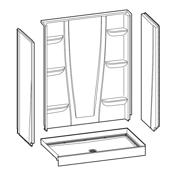
Installation Instructions
Shower
Level
Tape
Safety Glasses
Measure
— 1 —
4-Piece A
Composite Shower System Models
2
NOTE: Caulk is NOT
needed for this installation.
Advertisement
Table of Contents

Summary of Contents for Aquatic A2
- Page 1 Do not make modifications to the Aquatic fixture. This could adversely affect the safety and performance of the Aquatic fixture and void the warranty. Any failure to comply with the installation instructions and cautions may void the warranty. For questions concerning installation and maintenance of the Aquatic fixture, contact Technical Services at 1-800-945-2726.
-
Page 2: Installation Instructions
PLEASE READ ALL INSTALLATION INSTRUCTIONS COMPLETELY BEFORE BEGINNING THE INSTALLATION. PRE-INSTALLATION PLANNING 1. Review job print and Aquatic rough-in dimensions; verify all key dimensions against actual job conditions. MUST INSURE ROUGH DIMENSIONS ARE PROPER AND SQUARE. 2. Locate studs as required and in remodeling, if necessary, add studs at each end to provide a vertical nailing surface for the side nailing flanges of the Aquatic fixture. -
Page 3: Installation Procedure
Installation Instructions 4-Piece A Composite Shower System Models INSTALLATION PROCEDURE 6"x12" 6"Dia. 6"Dia. Check dimensions. For tub-showers, refer to Diagram 1A; for showers, refer to Diagram 1B. NOTE: If you’re adding additional accessories such as a grab bar–additional framing may be needed for support. Models 6030CT/CTM 60”... - Page 4 Installation Instructions 4-Piece A Composite Shower System Models INSTALLATION PROCEDURE, CONT. Lift and place the back wall, making sure locking tabs are engaged. Level back wall vertically & horizontally. Shim if necessary. Slide right side wall into position. Be sure locking mechanism is engaged. Check for level.
- Page 5 Installation Instructions 4-Piece A Composite Shower System Models INSTALLATION PROCEDURE, CONT. Using a hole saw (fine tooth or abrasive grit cutting edge), make necessary Install drain assembly per manufacturer’s instructions. Place base into framing pocket. openings for filler and valves, drilling from inside (smooth side) out. Level lengthwise and widthwise using 3 ft.
- Page 6 Installation Instructions 4-Piece A Composite Shower System Models INSTALLATION PROCEDURE, CONT. Fasten flanges along top of back wall with fasteners of choice (see Pre- Slide right side wall into position. Be sure locking mechanism is engaged. Installation Planning #12) into each corresponding stud. Pre-drill both NOTE: Finish caulking is not required, however, if using caulk, weep channel (vertical) side flanges and nail fasten to side studs 8”...
- Page 7 Installation Instructions 4-Piece A Composite Shower System Models INSTALLATION PROCEDURE, CONT. Slide left side wall into position. Be sure locking mechanism is engaged. Fasten flanges along top of left side wall with fasteners of choice NOTE: To accommodate any stud variation, you may have to add a bead of (see Pre-Installation Planning #12) into each corresponding stud.
-
Page 8: User Maintenance Instructions
Gel or Comet Gel. Read all labels carefully and DO NOT USE if they say “not suitable for use with fiberglass.” To keep your Aquatic fixture sparkling clean, apply a coat of good quality automotive paste wax or polish and buff to a high shine with a soft cloth or towel. -
Page 9: Instrucciones De Instalación
Revise cuidadosamente el nuevo mueble Aquatic para asegurarse de que no se haya dañado en el envío. Si encuentra algún daño, informe de inmediato al proveedor. Si el mueble Aquatic está dañado, no debe instalarlo bajo ninguna circunstancia. - Page 10 PLANIFICACIÓN PREVIA A LA INSTALACIÓN Revise los documentos del trabajo y las dimensiones preliminares de Aquatic. Verifique todas las dimensiones clave en relación con las condiciones de trabajo reales. DEBE ASEGURARSE DE QUE LAS DIMENSIONES PRELIMINARES SEAN CORRECTAS Y ESTÉN A ESCUADRA.
-
Page 11: Procedimiento De Instalación
Instrucciones de instalación Modelos de sistema de regadera de 4 piezas de resina compuesta A PROCEDIMIENTO DE INSTALACIÓN 6"x12" 6"Dia. 6"Dia. Verifique las dimensiones. Para tinas-regaderas, consulte el Diagrama 1A; para regaderas, consulte el Diagrama 1B. NOTA para 1B: Si debe agregar accesorios adicionales, como una barra de seguridad, puede necesitar usar un armazón de montaje adicional como soporte. Modelos 6030CT/CTM 60”... - Page 12 Instrucciones de instalación Modelos de sistema de regadera de 4 piezas de resina compuesta A PROCEDIMIENTO DE INSTALACIÓN, CONTINUACIÓN Nivele el panel posterior en sentido horizontal y vertical. Use cuñas Deslice el panel lateral derecho hasta colocarlo en posición. Asegúrese de si es necesario.
- Page 13 Instrucciones de instalación Modelos de sistema de regadera de 4 piezas de resina compuesta A PROCEDIMIENTO DE INSTALACIÓN, CONTINUACIÓN Instale el montaje de desagüe de acuerdo a las instrucciones del fabricante. Si lo desea, coloque material de relleno y cimentación. Si va a aplicar materiales de relleno y cimentación, siga estas instrucciones: Mezcle el material de relleno y cimentación.
- Page 14 Instrucciones de instalación Modelos de sistema de regadera de 4 piezas de resina compuesta A PROCEDIMIENTO DE INSTALACIÓN, CONTINUACIÓN Nivele el panel posterior en sentido horizontal y vertical. Use cuñas Clave o atornille los rebordes de toda la parte superior del panel posterior si es necesario.
- Page 15 Instrucciones de instalación Modelos de sistema de regadera de 4 piezas de resina compuesta A PROCEDIMIENTO DE INSTALACIÓN, CONTINUACIÓN Clave o atornille los rebordes de toda la parte superior del panel Deslice el panel lateral izquierdo hasta colocarlo en posición. Asegúrese de lateral derecho con los sujetadores que prefiera (consulte el punto que se enganche el mecanismo de sujeción.
-
Page 16: Instrucciones De Mantenimiento Para El Usuario
Agua dura: El agua de ciertas regiones, si no se seca después usar la unidad, puede quitar el color del mueble Aquatic. Este es un proceso natural fuera del control de Aquatic y Aquatic no se responsabiliza de ningún tipo de pérdida de color de la unidad por el efecto del agua dura. -
Page 17: Instructions D'installation
Nous vous remercions d’avoir choisi Aquatic. Pour assurer la performance maximale de votre appareil Aquatic, veuillez lire et suivre les instructions et mises en garde. Inspectez attentivement le nouvel appareil Aquatic à la recherche de tout dommage survenu en cours de transport. - Page 18 VEUILLEZ LIRE EN ENTIER TOUTES LES INSTRUCTIONS D’INSTALLATION AVANT DE COMMENCER L’INSTALLATION. PLANIFICATION AVANT L’INSTALLATION Prenez connaissance de ce guide ainsi que des dimensions pour l’installation de l’unité Aquatic, vérifiez toutes les principales dimensions sur le lieu de l’installation. ASSUREZ-VOUS QUE LES DIMENSIONS POUR L’INSTALLATION SONT APPROPRIÉES ET À ANGLE DROIT.
- Page 19 Instructions d’installation Modèles de système de douche en composite A en 4 pièces INSTRUCTIONS D’INSTALLATION 6"x12" 6"Dia. 6"Dia. Vérifiez les dimensions. Pour les bains-douches, reportez-vous au schéma 1A; pour les douches, reportez-vous au schéma 1B. REMARQUE : Il peut être nécessaire de renforcer la charpente si vous ajoutez des accessoires additionnels, telle une barre d’appui. Modèles 6030CT/CTM 60”...
- Page 20 Instructions d’installation Modèles de système de douche en composite A en 4 pièces INSTRUCTIONS D’INSTALLATION (SUITE) Soulevez la paroi arrière verticalement et horizontalement. Placez Faites glisser la paroi de droite en place. Assurez-vous que le mécanisme des cales de nivellement au besoin. de blocage est engagé.
- Page 21 Instructions d’installation Modèles de système de douche en composite A en 4 pièces INSTRUCTIONS D’INSTALLATION (SUITE) Installez la vidange conformément aux directives du fabricant. Si nécessaire, appliquez des matériaux de fondation. Les éléments suivants s’appliquent lors de l’utilisation de matériau de fondation : Mélangez le matériau de fondation. Placez trois ou quatre monticules de plâtre sur le sous-plancher autour, mais en évitant l’orifice de vidange.
- Page 22 Instructions d’installation Modèles de système de douche en composite A en 4 pièces INSTRUCTIONS D’INSTALLATION (SUITE) Soulevez la paroi arrière verticalement et horizontalement. Placez Fixez les brides le long du dessus du mur du fond à l’aide des attaches des cales de nivellement au besoin. choisies (voir la section 12 de la rubrique «...
- Page 23 Instructions d’installation Modèles de système de douche en composite A en 4 pièces INSTRUCTIONS D’INSTALLATION (SUITE) Fixez les brides le long du dessus du mur latéral droit à l’aide des attaches Glissez la paroi gauche en place. Assurez-vous que le mécanisme de choisies (voir la section 12 de la rubrique «...
-
Page 24: Instructions D'entretien Par L'utilisateur
Lisez soigneusement les étiquettes et N’UTILISEZ PAS LE PRODUIT si elles indiquent « non recommandé pour la fibre de verre ». Pour que votre accessoire de bain Aquatic soit propre et conserve son brillant, appliquez une couche de cire en pâte ou poli pour automobile de bonne qualité...
Need help?
Do you have a question about the A2 and is the answer not in the manual?
Questions and answers