
Related Manuals for LynTec RPC

Summary of Contents for LynTec RPC
- Page 1 LynTec RPC Instruction Bulletin Remote Power Controller Retain for future use. 139-0498-02 11/7/14...
- Page 2 No responsibility Square D for any consequences arising out of the use of this manual. is assumed by LynTec for any consequences arising out of the use of this manual. Class A FCC Statement...
-
Page 3: Table Of Contents
TCP/IP ......................................17 sACN ......................................17 DMX ......................................17 RS-232 ......................................17 RS-485 ......................................17 Switch Wiring Instructions ...............................18 LynTec SS-2 Switch Set ................................18 SS-2PL and SS-2LRP Locking Switch Sets ........................19 Initial Power up procedure ................................23 Chapter 5--Control Setup (Web Page)..............................24 OVERVIEW ......................................24 Status .........................................24 Control ........................................24... - Page 4 Assigning Contact Closures to Zones ..........................38 Individual Momentary Contact ON and OFF Pushbuttons ...................39 I/OR Setup ....................................40 Email Alert Setup ..................................41 Chapter Six: Operating your RPC ..............................42 Using the built-in web page ..............................42 Using a secondary controller ..............................42 Appendix A--RPC Quick Start Guides ...............................43 RPC to RPS Wiring Instructions ............................43...
-
Page 5: Chapter 1--Introduction
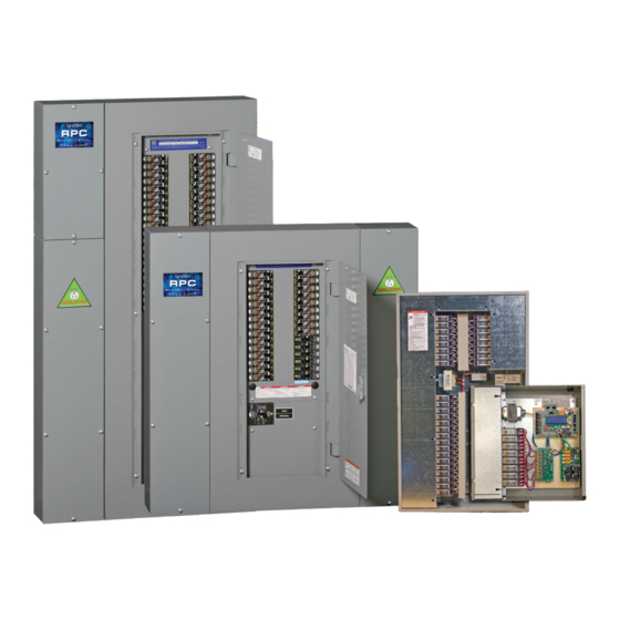
Introduction Chapter 1--Introduction OVERVIEW This bulletin explains how to install and operate the LynTec Remote Power Controller (RPC) and the RPCR relay panel. The controller uses remotely operated circuit breakers to control up to 167 remotely operated branch circuits. In the case of the RPCR, the controller can control up to 64 relays. -
Page 6: Controller Overview
Chapter One--Overview Controller Overview Figure 1–1 shows the parts of the RPC controller. Controller overview A brief description of each part follows in Table 1–1. Figure 1-1: RPC Controller A. DMX Input and Thru B. Off Button (Red) C. On Button (Green) D. - Page 7 Chapter One--Overview Controller Overview Table 1-1: Parts of the RPC Controller Component Description N. I/O Board Port Connects additional I/O boards to the controller. Up to two boards can be added for a total of 38 contact closure inputs. OR, the I/OR board may be added to provide outbound relay control O.
- Page 8 Chapter One--Overview Additional Boards Overview Figure 1–3 shows the parts of the additional slave Figure 1-3: Multi-Panel Expander Board board. A brief description of each part follows in Table 1–3. Table 1-3: Parts of the Multi-Panel Expander Board Component Description A.
-
Page 9: Chapter Two--Safety Precautions
Chapter Two--Safety Precautions Chapter Two--Safety Precautions This chapter contains important safety precautions that must be followed before attempting to install, service, or maintain electrical equipment. Carefully read and follow the safety precautions below. READ AND FOLLOW ALL SAFETY INSTRUCTIONS DANGER HAZARD OF ELECTRIC SHOCK, EXPLOSION, OR ARC FLASH This equipment must be installed and serviced only by... -
Page 10: Chapter Three--Quick Start Guide
Chapter Three--Quick Start Guide INTRODUCTION This chapter is a quick reference listing the steps necessary to install the RPC system. The steps in this chapter are provided as an installation checklist. For complete installation instructions, refer the chapter listed. Steps Reference 1. -
Page 11: Chapter 4--Wiring
To initially wire the RPCR connect the power breaker in your panel to the transformer in the RPCR. For additional RPCR wiring, skip to page 14. To initially wire the RPC follow these easy steps: 1. Install and connect all main and neutral feeds as per NEC. -
Page 12: Additional Control Options
Communication Power 1. If RPS Slave panels are being used in conjunction with an RPC Master panel, install and connect one 18 AWG six (6) conductor, (Belden 27600 A or equivalent) or two 18-24 AWG twisted pairs for data and one 16-18 AWG for power per RPS unit. - Page 13 Chapter Four--Wiring 2. At the RPS Slave panels, strip the cable sheath back approximately 20 inches. Cut the conductors for Left Bus B, Left Bus A, – and + down to approximately 4 inches and terminate them in the Left Bus screw-terminal header from left to right.
- Page 14 Chapter Four--Wiring Figure 4-3: Digital I/O Remote RJ-45 8PC Cable Switch and Sensor Wiring to I/O Port on Controller 24 VDC LED Indicator I/O Port Momentary ON Contact Switch Momentary OFF Contact Switch 24 VDC LED Indicator Maintained Contact Switch Light Sensor for Zone Control I/O Port...
-
Page 15: Emergency Shutdown Wiring
Emergency Shutdown Wiring: To connect your fi re alarm or emergency management system to the RPC, follow these steps. 1. From the fi re alarm unit or latching Emergency Shutoff switch, wire the Normally Open (NO) contacts to the IN and 24V positions of Digital I/O Port #1 on the Controller. -
Page 16: Emergency Lighting Wiring
Emergency Lighting Wiring: To connect your fi re alarm or emergency management system to the RPC, follow these steps. 1. From the fi re alarm unit or latching Emergency Lighting switch, wire the Normally Open (NO) contacts to the IN and 24V positions of Digital I/O Port #6 on the Controller. -
Page 17: Tcp/Ip
Chapter Four--Wiring Figure 4-6: Control Wiring Ethernet Cable to Facility Network 24 VDC LED Indicator ––++ Momentary Input Thru Momentary Analog Inputs for DMX-512 Control Contact RX TX Ethernet Digital I/O Analog Control Functions Cat 5e Inputs RS-232 RS-485 RS-232 Maintained 24 VDC LED Contact Switch... -
Page 18: Switch Wiring Instructions
Chapter Four--Wiring The I/O ports on your RPC controller allow for a variety of Switch Wiring Instructions switch options. Using a standard LynTec SS-2 Switch Set with illuminated ON LynTec SS-2 Switch Set switch. See Figure 4-6 1. Wire the ON switch to Digital I/O port 2 on the left edge of... -
Page 19: Ss-2Pl And Ss-2Lrp Locking Switch Sets
Chapter Four--Wiring Using a standard LynTec SS-2PL or SS-2 LRP Switch Set with SS-2PL and SS-2LRP Locking Switch illuminated ON switch. See Figure 4-7 Sets 1. Wire the ON switch to Digital I/O port 2 on the left edge of... - Page 20 Chapter Four--Wiring Figure 4-11: Complete RPC Wiring for Motorized Breaker Panels RS-232 Input Slave DMX Input Control DMX-512 Analog RS-232 Cat 5e L BusR BusP WR Control + + – – Controller Power 139-0498-0220...
- Page 21 Main Breaker options - Part # suffix -MHG3110, MHG3125, -MJG3150, -MJG3175, -MJG3200 (all 65k Amp Interrupt Rating) 28.00" Main Breaker wire: 3/0-350 kcmil Aluminum or Copper 200% Neutral has one feed lug that accepts two 350 kcmil wires. 139-0500-00 RPC 341 Mechanical 9/25/08 139-0498-02.21...
- Page 22 Chapter Four--Wiring Figure 4-13: RPCR-32 Mechanical Drawing 20” Power 34” Power supply Relay Driver 139-0498-0222...
-
Page 23: Initial Power Up Procedure
RPC will “beep” four times. Connect a computer with an Ethernet port and installed web browser program to the RPC Network connector using the provided crossover cable. Then enter the default IP address for the controller, 192.168.1.250. -
Page 24: Chapter 5--Control Setup (Web Page)
Chapter Five--Control Setup Chapter 5--Control Setup (Web Page) There are 5 main tabs on your RPC web page. This page will OVERVIEW give you a quick overview of the pages and their functions. STATUS The status page allows you to view the current status of the breakers and zones. -
Page 25: Setup
Chapter Five--Control Setup This section will guide you through the process of setting up yur Setup RPC Controller. First enter the IP address or NetBios name into your web browser. When the RPC screen pulls up. Select “Setup” and “SetupHome” Tabs. -
Page 26: Network Setup
If DHCP is enabled and available on the network, all these values will be obtained from the DHCP server. If DHCP is disabled and a static address is used, save changes and then press “Reset RPC” or the reset button on the controller to apply changes. 139-0498-02.26... - Page 27 Chapter Five--Control Setup Figure 5-3: Interface options The port type section is used to select the preferred Port Type communication protocol. The controller defaults to Ethernet (TCP/IP) for setup but can be controlled in conjunction with RS-232, sACN or DMX-512 protocols. For RS-232 operation use the following steps: RS-232 Select a baud rate in the dropdown box from 300 to 115,200...
- Page 28 Chapter Five--Control Setup For DMX operation use the following steps: The RPC allows up to four diff erent sets of DMX starting addresses within a single universe. In the fi rst set, enter the fi rst individual breaker address. All motorized breakers need to be assigned addresses manually.
-
Page 29: Panel Setup
Chapter Five--Control Setup This section explains how to setup your panel and Panel Setup motorized breakers for remote operation. To setup breakers, follow these steps: BREAKER SETUP 1. Under Setup, go to the Panels tab. 2. After breakers are installed by a qualifi ed electrician, click the “Scan Breakers”... -
Page 30: Zone Setup
Chapter Five--Control Setup 4. Assign names to the breakers. (Figure 5-5) Figure 5-5 Breakers can be controlled individually or arranged into zones. ZONE SETUP Breakers in zones can be toggled at 25 ms intervals (Grouped Operation), at variable intervals (Sequenced Operation), or via DMX or sACN. - Page 31 Chapter Five--Control Setup 2. Name the Zone. (Figure 5-7) 3. Choose Grouped, Sequenced, DMX or sACN operation. Note: DMX and sACN may not be used within the same RPC (Figure 5-7) Figure 5-7 Name the Zone Choose operation type from the dropdown 4.
- Page 32 Chapter Five--Control Setup 5. Select a breaker to add to the zone by clicking on the breaker you want to add. Only motorized breakers (indicated in green) may be added to zones. (Figure 5-10) Figure 5-10 Click on the green oval to add a breaker to a zone.
- Page 33 Chapter Five--Control Setup 8. Click the “Close” button when fi nished to save. Or, click “Remove” to remove the breaker from the zone. 9. When fi nished adding breakers to the zone, click the “Test Mode” (Figure 5-12) button to do a blind test (breakers will not actually toggle).
-
Page 34: Global Preferences
GLOBAL PREFERENCES many features and preferences in your RPC system. SETUP In addition to labeling breakers, each panel in your RPC system Labeling can be named (up to 16 characters) and the changes dated (Figure 5-14). For multi-panel systems, scroll down to see additional panels. -
Page 35: Global Control Preferences
Chapter Five--Control Setup The following features can be selected for additional system Global Control Preferences fl exibility Figure 5-16 Table 5-1 All Breakers On/Off Turns all the breakers on or off by order of zone and sequence Hurry-Off Turns breakers off rapidly without sequencing E. -
Page 36: Selecting Breakers For Emergency Shutdown, Emergency Lighting Or Brownout
Chapter Five--Control Setup Selecting breakers for Emergency Shutdown, Emergency Lighting or Brownout Figure 5-17 Select breakers to actuate Select breakers for in the event of a brownout in emergency shutdown in green outlined check boxes. pink outlined check boxes. Select breakers for emergency lighting in yellow outlined check boxes. -
Page 37: Schedule Setup
Chapter Five--Control Setup Schedule Setup Follow these steps to set a schedule (not compatible with DMX or sACN). 1. Enable Schedules in Setup Home tab 2. Rename each schedule as desired 3. Assign weekday (M-F) on and off times by clicking on time and off time buttons, using pull-down menu and clicking the pick button to select. -
Page 38: Contact Closure Setup
Chapter Five--Control Setup Contact Closure Setup Confi gure the digital I/O port and link it to a zone as follows: Note: If the Emergency Shutoff feature is selected, the fi rst position in the Onboard fi eld (on the Controller) is automatically assigned to that. -
Page 39: Individual Momentary Contact On And Off Pushbuttons
Chapter Five--Control Setup Using a standard LynTec SS-2 Switch Set with illuminated ON Individual Momentary Contact ON and switch or two illuminated pushbuttons: OFF Pushbuttons Confi gure the Digital I/O port and link it to a zone as follows: 1. Follow the previous instructions for naming the contact closure and setting closure type. -
Page 40: I/Or Setup
Chapter Five--Control Setup I/OR Setup The I/OR board combines the imput function of the I/O board with output devices (either low-voltage SPDT relays or high- current transistors) to control external devices. In the contact closure setup page the fi rst eight contacts in the I/OR Module are standard I/O ports. -
Page 41: Email Alert Setup
Chapter Five--Control Setup Email Alert Setup Follow these steps to set an email alert 1. Go to Setup Alerts tab 2. Enter email addresses. 3. Select alert types (tripped breaker, BO/EO/EL, On Recovery and/or Temperature 4. If using Temperature alerts, enter the temperature threshold. -
Page 42: Chapter Six: Operating Your Rpc
Chapter Six--Operation Chapter Six: Operating your RPC Figure 6-1 To operate the RPC using the built in web page, select the Using the built-in web page control tab from the top of the page. Once on the CONTROL page, simply click each breaker for individual control. Or, click a zone for zone control. -
Page 43: Appendix A--Rpc Quick Start Guides
Appendix A Appendix A--RPC Quick Start Guides RPC to RPS Wiring Instructions Figure A-1 Left Bus B Twisted Pair Left Bus A Right Bus B Twisted Pair Right Bus A Slave Common Slave +24VDC Slave Panel 2 Power Slave Panel 3... - Page 44 Appendix A 1. If RPS Slave panels are being used in conjunction with an RPC Master panel, install and connect one 18 AWG six (6) conductor (Belden 27600 A or equivalent) or two 18-24 AWG twisted pairs for data and one 16-18 AWG for power per RPS unit.
-
Page 45: Rpc Quickstart Guide
Appendix A RPC Quickstart Guide 139-0498-02.45... - Page 46 Appendix A 139-0498-02.46...
-
Page 47: Rpcr Quickstart Guide
Appendix A RPCR Quickstart Guide 139-0498-02.47... - Page 48 Appendix A 139-0498-02.48...
-
Page 49: Rpc Contact Closure Wiring Instructions
Appendix A RPC Contact Closure Wiring Instructions 139-0498-02.49... - Page 50 Appendix A 139-0498-02.50...
-
Page 51: Appendix B--Rs-232 And Tcp/Ip Protocols
Appendix A Appendix B--RS-232, Telnet and TCP/ IP Protocols RS-232/TELNET PROTOCOL Note: Telnet port = 23. Send Telnet commands to RPC IP address/23 (e.g. 192.168.1.250/23) Table B-1 Command Codes Command Decimal Hexidecimal Start Byte 0xB0 Activate breakers 0xB4 Deactivate breakers... - Page 52 Appendix B Deactivate breakers 0xB0, 0xB5, breaker_address_1, …, breaker_address_n, 0xF0 breaker_address_1, …, breaker_address_n – addresses of reakers to be deactivated n<=168 Activate/deactivate breakers 0xB0, 0XB5, breaker_address_1, …, breaker_address_m, 0xB6, breaker_address_1, …, breaker_address_n, 0xF0 breaker_address_1, …, breaker_address_m – addresses of breakers to be activated breaker_address_1, …, breaker_ address_n –...
-
Page 53: Zone Related Commands
Appendix B Reply to request breakers status command: Same format as “Request Bus Status”; contains addresses and status of the breakers specifi ed in the request command Reply to request all breakers status command: status of all breakers 0xB0, 0xB6, byte_1, …, byte_84, 0xF0 byte_i: bits 7-4: status of breaker # 2i, bits 3-0: status of breaker # 2i-1, i=1-84 Reply to request bus status command: status of all breakers... -
Page 54: Event Related Commands
Appendix B 0xB0, 0xB9, 0xF0 Reply to activate/deactivate zone command: status of updated zones 0xB0, 0xC9, zone_address_i, zone_status_i, zone_address_j, zone_ status_j, …, zone_address_n, zone_status_n, 0xF0 zone_address_i, zone_status_i, zone_address_j, zone_status_j, …, zone_address_n, zone_status_n – addresses and status of zones updated by the command reply is generated for Reply to request zone status command: status of all 12 zones 0x40, 0xB9, byte_1, byte_2, byte_3, 0x80 byte_i: bits 7-6: status of zone # 4i, bits 5-4: status of zone 4i-1,... - Page 55 Status Processing Device Discovery Beacon request “AMX\r” Beacon “AMXB<-SDKClass=Utility><-Make=Lyntec><-Model=RPC><- Revision=1.1.4>\r” (rev changed from 1.1.3; 1.1.3 supported old protocol) Emergency override response If system is in Emergency Override mode, it replies to to breaker, zone, or event on/ breaker, zone or event on/off command with emergency...
-
Page 56: Checksum
0xCE, 0xD0, 0xD4 TCP/IP PROTOCOL TCP/IP communications and control via a third party control system is facilitated by the use of the HTTP GET command. In the example below, GET= the RPC’s IP address Example of GET command: GET /p2.rpc?IPB002=1 Three modes of control are: Breaker control = “B”... -
Page 57: Events Control = E
Event 7 = “DMX/sACN” Event 8 = “EL” Emergency Lighting Verifi cation Scheme: The following GET command will return the current status of all breakers, zones and events in the RPC system. GET /p2.rpc The system will return the following: breakers=10110111111111111111... -
Page 58: Appendix C--Troubleshooting
Appendix C--Troubleshooting/FAQ Appendix C--Troubleshooting TROUBLESHOOTING THE Use the following table if you need to troubleshoot the RPC controller. CONTROLLER DANGER HAZARD OF ELECTRIC SHOCK, EXPLOSION, OR ARC FLASH This equipment must be installed and serviced only by qualifi ed electrical personnel. - Page 59 Appendix C--Troubleshooting/FAQ Table C-1: RPC Controller Troubleshooting Condition Possible Causes Solutions Verify that the power supply’s LED status indicators are ON. Make sure the 15A breaker that provides power to Power supply is not energized. the power supply is on. Also, verify that the power supply line terminal is secured.
-
Page 60: Appendix D--Rpc System Components
Appendix D The LynTec system consists of control buses, a panelboard, Appendix D--RPC System remotely operated circuit breakers, a power supply, a buffer, Components a transducer and a controller. Optional expansion boards are available to add up to three additional panels or 16 or 32 additional I/o outputs. -
Page 61: Control Bus
ON and OFF. The circuit breaker works with the RPC controller, power supply, and control buses to provide a remote power switching system in a panelboard. Figure D-3... -
Page 62: Power Supply
(up to four panels). This is a capacitive buffer and is lead and acid free. Figure D-5 Transducer The transducer converts incoming AC line voltage to a varying DC output, allowing the RPC to monitor line voltage. Figure D-6 139-0498-02.62... -
Page 63: Controller
Appendix D Controller The RPC Controller provides control logic for the operation of a RPC system. The controller uses remotely operated circuit breakers to control up to 167 remotely operated branch circuits. The built in web server allows for easy setup and operation. Also, it provides input channels for connecting external dry-contact control devices. - Page 64 Appendix D Inputs Six (6) independently confi gurable digital inputs/outputs Input Types Maintained N.O. Maintained N.C. Momentary N.O. Momentary N.C. Momentary toggle Three (3) analog inputs 0-5 or 0-10VDC Thirty-two (32) I/O ports on optional expander boards Status Output 24 Vdc (60mA maximum load for all outputs combined) Indicator output on each I/O port Auxiliary Power Supply...
Need help?
Do you have a question about the RPC and is the answer not in the manual?
Questions and answers