
Subscribe to Our Youtube Channel
Related Manuals for Micro Motion CDM100P

Summary of Contents for Micro Motion CDM100P
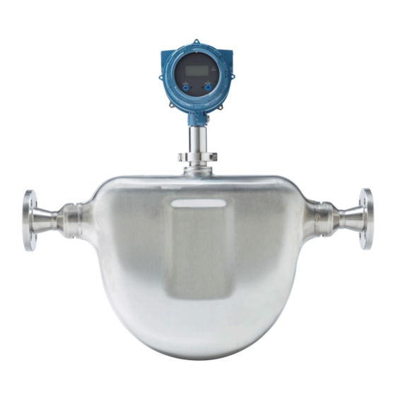
- Page 1 Installation Manual MMI-20020974, Rev AC May 2015 ® Micro Motion Compact Density Meters Peak performance precision density meter installation...
- Page 2 Safety and approval information This Micro Motion product complies with all applicable European directives when properly installed in accordance with the instructions in this manual. Refer to the EC declaration of conformity for directives that apply to this product. The EC declaration of...
-
Page 3: Table Of Contents
Contents Contents Chapter 1 Planning ...........................1 Installation checklist ........................1 Best practices ..........................2 Pressure drop in the meter ......................5 Power requirements ........................6 Perform a pre-installation meter check ...................9 Chapter 2 Mounting ........................11 Mount the meter ..........................11 Rotate the electronics on the meter (optional) ................12 Rotate the display on the transmitter (optional) ................13 Chapter 3 Wiring ........................... - Page 4 Contents Micro Motion Compact Density Meter...
-
Page 5: Chapter 1 Planning
Consider the maximum cable length between the meter and transmitter. The maximum recommended distance between the two devices is 1000 ft (300 m). Micro Motion recommends using Micro Motion cable. □ For optimal performance, install the meter in the preferred orientation. -
Page 6: Best Practices
Thermally insulate the meter and the inlet and bypass-loop pipeline to maintain stable temperatures. • There are no pipe run requirements for Micro Motion meters. Straight runs of pipe upstream or downstream are unnecessary. • Keep the meter tubes full of process fluid. - Page 7 Planning Figure 1-1: Bypass installation: S-Bend Figure 1-2: Bypass installation: Pressure bend Figure 1-3: Bypass installation: Laminar flow Important The laminar flow installation is only recommended for processes using refined, clean fluids with low viscosity. Installation Manual...
- Page 8 Planning Figure 1-4: Bypass installation: Pitot tube Vent Figure 1-5: Bypass installation: Orifice plate Orifice plate Micro Motion Compact Density Meter...
-
Page 9: Pressure Drop In The Meter
In addition, these charts show how the meter compares to the Micro Motion 7835/7845 liquid density meters. Important For the most accurate pressure drop calculations using your process variables, use the Micro Motion product selector available at www.micromotion.com. Installation Manual... -
Page 10: Power Requirements
Density = 800 kg/m Viscosity = 10 cP 0.70 0.60 0.50 0.40 0.30 7835 7845 CDM100 0.20 0.10 0.00 Flow Rate ( /hr) Power requirements Following are the DC power requirements to operate the meter: Micro Motion Compact Density Meter... - Page 11 Planning • Explosion-proof/flameproof meters: 24 VDC, 0.65 W typical, 1.1 W maximum Minimum recommended voltage: 21.6 VDC with 1000 ft of 24 AWG (300 m of 0.20 mm ) power-supply cable At startup, power source must provide a minimum of 0.5 A of short-term current at a minimum of 19.6 V at the power-input terminals.
- Page 12 2952.76ft 3280.84ft Distance of installation Power cable recommendations for intrinsically safe meters Figure 1-11: Minimum wire gauge (AWG per feet) Minimum Wire Gauge 22.8V 1200 1500 1800 2100 2400 2700 3000 Distance of Installation (ft) Micro Motion Compact Density Meter...
-
Page 13: Perform A Pre-Installation Meter Check
Visually inspect the meter for any physical damage. If you notice any physical damage to the meter, immediately contact Micro Motion Customer Support at flow.support@emerson.com. Position and secure the meter in a vertical position with the flow arrow pointing upward. - Page 14 If the meter passes the test, then it has not drifted or changed during shipment. For more information on performing a KDV check, see the configuration and use manual that shipped with the product. Micro Motion Compact Density Meter...
-
Page 15: Chapter 2 Mounting
Mounting Mounting Topics covered in this chapter: • Mount the meter • Rotate the electronics on the meter (optional) • Rotate the display on the transmitter (optional) Mount the meter Use your common practices to minimize torque and bending load on process connections. To reduce the risk of condensation or excessive moisture, the transmitter conduit opening should not point upward (if possible). -
Page 16: Rotate The Electronics On The Meter (Optional)
Rotate the electronics on the meter (optional) You can rotate the transmitter on the meter up to 90°. Using a 4 mm hex key, loosen the cap screw that holds the transmitter in place. Micro Motion Compact Density Meter... -
Page 17: Rotate The Display On The Transmitter (Optional)
Mounting Figure 2-2: Component to secure transmitter in place A. M5 socket-head cap screw Rotate the transmitter clockwise to the desired orientation up to 90°. Secure the cap screw in place and tighten to 60 lb·in (6.8 N·m). Rotate the display on the transmitter (optional) The display on the transmitter electronics module can be rotated 90°... - Page 18 If you have removed the display screws, line them up with the matching holes on the sub-bezel, then reinsert and tighten them. Place the display cover onto the main enclosure. Turn the display cover clockwise until it is snug. If appropriate, power up the meter. Micro Motion Compact Density Meter...
-
Page 19: Chapter 3 Wiring
Wiring Wiring Topics covered in this chapter: • Available output terminals and wiring requirements • Explosion-proof/flameproof or non-hazardous output wiring • Hazardous area output wiring ™ • Processor wiring for remote-mount 2700 FOUNDATION fieldbus option • Wiring to external devices (HART multidrop) •... -
Page 20: Explosion-Proof/Flameproof Or Non-Hazardous Output Wiring
CAUTION! Meter installation and wiring should be performed by suitably trained personnel only in accordance with the applicable code of practice. Procedure Wire to the appropriate output terminal and pins (see Figure 3-1). Micro Motion Compact Density Meter... - Page 21 Wiring Figure 3-1: Wiring the Analog outputs mA1+ HART RS-485 A RS-485 RS-485 B A. 24 VDC (250 Ω resistance) B. R load C. HART-compatible host or controller; and/or signal device D. Signal device Note Ω is For operating the milliamp outputs with a 24V supply, a maximum total loop resistance of 657 allowed.
- Page 22 CAUTION! Meter installation and wiring should be performed by suitably trained personnel only in accordance with the applicable code of practice. Procedure Wire to the appropriate output terminal and pins (see Figure 3-2). Micro Motion Compact Density Meter...
- Page 23 Wiring Figure 3-2: Wiring the TPS or Discrete output version mA1+ HART TPS/DO RS-485 A RS-485 RS-485 B A. 24 VDC (250 Ω resistance) B. R load C. HART-compatible host or controller; and/or signal device Ω resistance recommended) D. R (500 load E.
-
Page 24: Hazardous Area Output Wiring
Wiring Hazardous area output wiring Micro Motion provides safety barrier and galvanic isolator installation kits for wiring the meter in a hazardous environment. These kits provide the appropriate barriers or isolators depending on the outputs available and approvals required. Information provided about wiring the safety barriers and galvanic isolators is intended as an overview. - Page 25 Wiring RS-485 output and cable parameters All connections to the meter receive their power from the connected intrinsically safe barrier. All cable parameters are derived from the output parameters of these devices. The RS-485 connection also receives power from the connected barrier (MTL7761AC), although this connection has specific output and cable parameters.
- Page 26 Li + Lcable ≤ La 3.3.2 Wire all intrinsically safe using safety barriers Micro Motion provides a safety barrier installation kit for wiring the meter in a hazardous area. Contact your local sales representative or Micro Motion Customer Support at flow.support@emerson.com for more information on ordering a barrier kit.
- Page 27 Wiring Figure 3-3: Intrinsically safe mA/DO/TPS output wiring using safety barriers Hazardous Area Non-Hazardous Area mA1+ 250 Ω MTL7728P+ HART 24 VDC mA2/ MTL7728P+ TPS/DO 24 VDC RS-485 A RS-485 MTL7761AC RS-485 B 24 VDC MTL7728P+ A. HART/Field Communicator device B.
- Page 28 Wire the intrinsically safe Analog outputs version using galvanic isolators Micro Motion provides a galvanic isolator installation kit specific to wiring the Analog version of the meter in a hazardous area. Contact your local sales representative or Micro Motion Customer Support at flow.support@emerson.com...
- Page 29 Wiring Figure 3-4: Intrinsically safe output wiring using galvanic isolators (mA outputs option) Hazardous Area Non-Hazardous Area mA1+ 24 VDC HART 250 Ω 24 VDC 250 Ω RS-485 A RS-485 RS-485 B 24 VDC LINK A. HART/Field Communicator device B. Signal device CAUTION! •...
- Page 30 Wire the intrinsically safe Time Period Signal (TPS) or Discrete output version using galvanic isolators Micro Motion provides a galvanic isolator installation kit specific to wiring the Time Period Signal (TPS) and Discrete versions of the meter in a hazardous area. Contact your local sales representative or Micro Motion Customer Support at flow.support@emerson.com...
- Page 31 Wiring Figure 3-5: Hazardous area output wiring using galvanic isolators (TPS and Discrete output options) Hazardous Area Non-Hazardous Area mA1+ 24 VDC HART 250 Ω 1 kΩ 1 kΩ TPS/DO 24 VDC RS-485 A RS-485 RS-485 B 24 VDC LINK A.
-
Page 32: Processor Wiring For Remote-Mount 2700 Foundation Fieldbus ™ Option
3.4.1 RS-485 entity parameters for the remote-mount 2700 ™ FOUNDATION fieldbus option DANGER! Hazardous voltage can cause severe injury or death. To reduce the risk of hazardous voltage, shut off power before wiring the meter. Micro Motion Compact Density Meter... - Page 33 Wiring DANGER! Improper wiring in a hazardous environment can cause an explosion. Install the meter only in an area that complies with the hazardous classification tag on the meter. Table 3-5: RS-485 output and cable entity parameters Cable parameters for intrinsically safe circuit (linear) Voltage (U 17.22 VDC Current (I...
- Page 34 3. Strip all but 1/2 inch (12 mm) of shielding. Wrap the drain wires twice around the shield and cut off the excess drain wires. Drain wires wrapped around shield Go to the shielding procedure Micro Motion Compact Density Meter...
- Page 35 Micro Motion offers two types of 4-wire cable: shielded and armored. Both types contain shield drain wires. The 4-wire cable supplied by Micro Motion consists of one pair of red and black 18 AWG (0.75 mm ) wires for the VDC connection, and one pair of white and green 22 AWG (0.35 mm...
- Page 36 The inner individual screen(s) should be connected at only one end, the controller end. • Metal cable glands should be used where the cables enter the meter amplifier box. Unused cable ports should be fitted with metal blanking plugs. Micro Motion Compact Density Meter...
-
Page 37: Wiring To External Devices (Hart Multidrop)
Wiring Wiring to external devices (HART multidrop) You can wire up to three external HART devices with the meter. The following information provides wiring diagrams for making those connections in safe and hazardous environments. 3.5.1 Wire mA1 in a HART multi-drop environment Important To wire power and outputs, see Wire power and outputs in a HART single-loop... - Page 38 You can wire up to three external HART devices in an intrinsically safe environment. Following are diagrams showing a HART multidrop connection using a single barrier connection (see Figure 3-11) and multiple barrier connections (see Figure 3-12). Micro Motion Compact Density Meter...
- Page 39 Wiring When connecting to a single barrier, do the following to determine your cable parameters (for each device): • Sum the C and L parameters for each device connected. • Subtract the sum from the C and L for the barrier. •...
- Page 40 For safety, do not terminate the inner individual screens to earth in a hazardous area. • Use metal cable glands where the cables enter the meter amplifier box. Fit unused cable ports with metal blanking plugs. Micro Motion Compact Density Meter...
- Page 41 Wiring Figure 3-12: Wiring external devices in an intrinsically safe area (multiple barriers) Hazardous Area Non-Hazardous Area Barrier 1 24 VDC Barrier 2 Barrier 3 MTL7728P+ HART Device 1 HART Device 2 HART Device 3 Meter (mA+/HART output) HART/Field Communicator CAUTION! •...
-
Page 42: Wiring To Signal Converters And/Or Flow Computers
When wiring the meter to an active HART host or signal converter/flow computer, you are not required to provide external power to the output connections. These active devices provide the 24 VDC necessary for these connections. Micro Motion Compact Density Meter... - Page 43 Wiring 3.6.1 Wire to a signal converter/flow computer in an explosion-proof/flameproof or non-hazardous area Figure 3-13: Wiring to a signal converter/flow computer in an explosion-proof/ flameproof or non-hazardous area mA1+ HART RS-485 A RS-485 RS-485 B 24 VDC Active HART host Active signal converter/flow computer CAUTION! •...
- Page 44 For safety, do not terminate the inner individual screens to earth in a hazardous area. • Use metal cable glands where the cables enter the meter amplifier box. Fit unused cable ports with metal blanking plugs. Micro Motion Compact Density Meter...
-
Page 45: Chapter 4 Grounding
The meter must be grounded according to the standards that are applicable at the site. The customer is responsible for knowing and complying with all applicable standards. Prerequisites Micro Motion suggests the following guides for grounding practices: • In Europe, EN 60079-14 is applicable to most installations, in particular Sections 12.2.2.3 and 12.2.2.4. - Page 46 Emerson Process Management The Emerson logo is a trademark and service mark of Emerson 1-2-5, Higashi Shinagawa Electric Co. Micro Motion, ELITE, ProLink, MVD and MVD Direct Shinagawa-ku Connect marks are marks of one of the Emerson Process Tokyo 140-0002 Japan Management family of companies.
Need help?
Do you have a question about the CDM100P and is the answer not in the manual?
Questions and answers