Table of Contents
Advertisement
Operation, Parts and Maintenance Manual
Model:
Serial #:
Options:
6926 Smithville Hwy. McMinnville, TN 37110
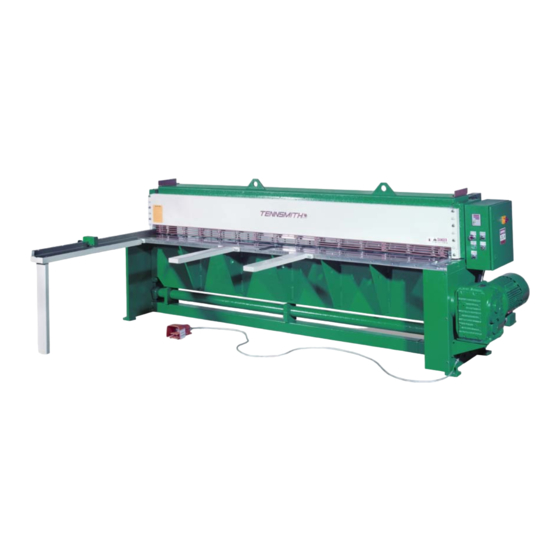
Model LM1010-2x
Phone: 931-934-2211 • Fax: 931-934-2220
Email info@tennsmith.com
www.tennsmith.com
Proudly Made in the USA
A Family Tradition Since 1928
Model LM1010 Performance "R"
Prepared for:
Date of Manufacture:
Inspected By:
Notes:
Advertisement
Table of Contents

Related Manuals for Tennsmith LM1010-2x


Summary of Contents for Tennsmith LM1010-2x
- Page 1 Model LM1010 Performance “R” Operation, Parts and Maintenance Manual Model LM1010-2x Model: Prepared for: Serial #: Date of Manufacture: Options: Inspected By: Notes: 6926 Smithville Hwy. McMinnville, TN 37110 Phone: 931-934-2211 • Fax: 931-934-2220 Email info@tennsmith.com www.tennsmith.com Proudly Made in the USA...
-
Page 2: Table Of Contents
TABLE OF CONTENTS SUBJECT PAGE NUMBERS SHEAR SPECIFICATIONS…………………………………… 2 SAFETY LABELING AND INSTUCTIONS…………………. 3-6 INSTALLATION………………………………………………. 6 OPERATING INSTRUCTIONS………………………………..7-8 BLADE CLEARANCE/ADJUSTMENT………………………. 9 BLADE ROTATION/REPLACING…………………………… 10-11 BACKGAUGE INFORMATION……………………………… 11 HOLDDOWN INFORMATION……………………………….. 11 SHEET SUPPORT SYSTEM INFORMATION……………….. 12 MAINTENANCE………………………………………………. 12 WARRANTY INFORMATION……………………………….. 13 PARTS VIEW AND DESCRIPTIONS…………………………... -
Page 3: Shear Specifications
LM 1010 Specifications Maximum Shearing Capacity, Mild Steel 10 gauge/3,5mm Maximum Capacity of Mild Steel is rated at 80,000 psi tensile 44,000 yield Maximum Shearing Capacity, Stainless Steel 14 gauge/2,0mm Maximum Capacity of Stainless Steel is rated at 90,000 psi tensile 55,000 yield Maximum Cutting Length 121 in/3073mm Back gauge Range... -
Page 4: Safety Labeling And Instuctions
ATTENTION Please verify that the following safety decals are attached to the LM Shear. If you do not locate all of the decals, please contact Tennsmith to replace any missing or unreadable safety labels. NEVER operate this machine without the proper safety... - Page 6 SAFETY INSTRUCTIONS Do not operate service or perform maintenance prior to reading and understanding the instruction manual. Become familiar with and understand the hazards and limitations of your shear. Wear approved eye protection and protective footwear while operating the machine. Be certain this machine is properly wired and grounded to conform to the National Electric Code.
-
Page 7: Installation
Insure that the point of operation safeguarding is provided, used and maintained for any applicable use or service which exposes bodily hazards. For more details please refer the ANSI Standards for Shear Operations. Keep the Work area around this machine clear and clean to avoid tripping or slipping. -
Page 8: Operating Instructions
LM Control Box Overlay... - Page 9 It is unsafe to operate this shear without the illuminated switch. Please contact Tennsmith if you need assistance replacing the bulb. 2. To the right of the Push/Pull Switch is the Jog/Run Switch. This selector type switch is designated 2 on the previous page.
-
Page 10: Blade Clearance/Adjustment
BLADE CLEARANCE The blade clearance on the LM1010 was set at the factory to .004 in. on the ends of the blades with a .003 gap in the center of the machine. At this setting, your shear should provide satisfactory results over a broad range of materials and thickness. However, when shearing lighter gauge materials a tighter blade gap may be desired. -
Page 11: Blade Rotation/Replacing
REPLACING/ROTATING BLADES The blades on the LM Series shears are four edged blades constructed of high carbon, high chromium tool steel. Top and bottom blades are interchangeable. Upon utilizing all four edges of you blades, you may return the blades to the factory for re-sharpening or to a qualified blade re-sharpener, such as a blade manufacturer. -
Page 12: Backgauge Information
Otherwise, crashing of the blades could result in severe damage to the machine. 7. Reposition the hold down assembly. BACKGAUGE INFORMATION The LM shear is fitted with a front operated back gauge as standard equipment. The gauge was installed and calibrated at the factory and shipped intact mounted on the shear. Inspect the gauge carefully to determine any possible movement or damage in transit. -
Page 13: Sheet Support System Information
SHEET SUPPORT SYSTEM 1. Single Stroke: When the foot pedal is activated, the sheet support will drop down and remain down until the cycle is complete and then return to the up position. 2. Continuous Stroke: When the foot pedal is activated, the sheet support will drop down and stay down as long as the foot pedal is activated. -
Page 14: Warranty Information
LM SERIES 3-YEAR LIMITED WARRANTY TENNSMITH machinery and component parts are carefully inspected at various stages of production and are tested and inspected prior to shipment. We agree that for a period of twelve (12) months from the date of delivery from our authorized distributor to replace, at our option, any machine (or component part thereof) proving defective within the above period. -
Page 15: Parts View And Descriptions
LM Machine PARTS View... - Page 16 MODEL LM1010 PARTS LIST ITEM# LM PART# DESCRIPTION QTY. 1010001 CUTTER HEAD 101002L GIBB PLATE LEFT 101002R GIBB PLATE RIGHT 1010003 BLADE TOP & BOTTOM 1010004 SET SCREW, ROD MOUNTING 1010005 BOLT, BLADE MOUNTING 1010006 LOCK WASHER, BLADE 1010007 DOWEL PIN, GIBB PLATE 1010008 BOLT, GIBB PLATE 1010009...
- Page 17 LM 2x Back gauge Crank Assembly...
- Page 18 LM 2x Back Assembly gauge Crank Parts List ITEM# LM PART# DESCRIPTION QTY. 20083 THRUST WASHER 20085 LOCK WASHER, BOLT, SPROCKET MOUNTING 20086 SPACER RING, SPROCKET MOUNTING 20087 BEARING, SPROCKET MOUNTING 20088 SPROCKET 20089 CHAIN 20102 BOLT, SPROCKET AND SPACER BLOCK MOUNTING 20103 FLAT WASHER, BOLT, SPROCKET SPACER BLOCK 20139...
- Page 19 LM 2x Back gauge Assembly Pointer LM 2x Back gauge Pointer Assembly Parts List ITEM# LM PART# DESCRIPTION QTY. 20136 COVER, SCALE POINTER ASSEMBLY 137A 2137A SCALE, INCH/METRIC 30 ICHES 20138 SCREW, SCALE BRACKET AND COVER MOUNTING 20139 LOCK WASHER, SCREW, SCALE BRACKET 20140 BRACKET, SCALE MOUNTING 20141...
- Page 20 LM 2x Back gauge Pointer Assembly Parts List ITEM# LM PART# DESCRIPTION QTY. 20160 NUT, SET SCREW, POINTER BLOCK 20161 CLAMP, CHAIN LOCK, POINTER BLOCK 20162 BOLT, CLAMP MOUNTING, POINTER BLOCK 20163 BEARING, POINTER BLOCK 20164 SCREW, POINTER MOUNTING 20165 POINTER, SCALE LM 2x Back gauge Drive Assembly Parts List ITEM#...
- Page 21 LM 2x Back gauge Assembly Drive...
- Page 22 LM 2x Back Arm Assembly gauge LM 2x Back gauge Arm Assembly Parts List ITEM# LM PART# DESCRIPTION QTY. 20094 SET SCREW, SHAFT MOUNTING 20095 SUPPORT BLOCK, FRONT 20096 SET SCREW, SUPPORT BLOCK MOUNTING 20097 SUPPORT ROD 20098 SUPPORT BLOCK, REAR 20099 BOLT, REAR SUPPORT BLOCK ADJUSTING 20100...
- Page 23 LM Four Foot Squaring Arm LM Four Foot Squaring Arm Parts List ITEM# LM PART# DESCRIPTION QTY. 40005 BOLT, TABLE, SQUARING ARM MOUNTING 40006 LOCK WASHER, BOLT, TABLE SQ ARM MOUNTING 40046 SET SCREW, SCALE 40181 NUT, LOCK HANDLE, BLOCK SQ ARM 40185 RATCHET STUD, LOCK HANDLE, BLOCK SQ ARM 40186...
- Page 24 LM Front Return Sheet Support System LM Front Return Sheet Support System ITEM# LM PART# DESCRIPTION QTY. FS10195 SUPPORT BRACKET, FRONT RETURN, SYSTEM 195A FS10195A SUPPORT BRACKET, FRONT RETURN, SYSTEM FS10197 LOCK WASHER, BRACKET MOUNTING FS10198 SCREW, BRACKET MOUNTING FS10199 WASHER, RACK MOUNTING FS10200 TEFLON WASHER, RACK MOUNTING...
- Page 25 LM Rear Sheet Support System LM Rear Sheet Support System Parts List ITEM# LM PART# DESCRIPTION QTY. RS10197 SCREW, BRACKET MOUNTING RS10198 LOCK WASHER, BRACKET MOUNTING RS10199 WASHER, RACK MOUNTING RS10200 TEFLON WASHER, RACK MOUNTING RS10201 STRIPPER BOLT, RACK MOUNTING RS10202 BRACKET, AIR CYLINDER MOUNTING RS10203...
-
Page 26: Electrical Diagram And Parts List
LM1010 WIRING DIAGRAM... - Page 27 LM1010 Electrical Parts List SQUARE D COMPONENTS 240 VOLT MACHINE LM PART# DESCRIPTION QTY. 9007C062 LIMIT SWITCH BODY 9007CT62 LIMIT SWITCH RECEPTACLE 9007D LIMIT SWITCH HEAD TOP ROLLER 9070T500D1SF41 500VA 480/240 XFORMER LC2D40G7 40 AMP 120 VAC REVERSING CONTACTOR LRD3355 OVERLOAD ELAY FLA 30-40 XB2BN4161 3 POSITION PUSH PULL OPERATOR...
- Page 28 LM1010 OPTIONS WIRING DIAGRAM...
- Page 29 LM1010 OPTIONS Parts List Light Beam LM1010 LM PART# DESCRIPTION QTY. ZB4BD2 2 POSITION MAINTAINED SELECTOR SWITCH ZBE101 1 N/O CONTACT BLOCK ZB4Z009 MOUNTING COLLAR LIGHTS OFF – ON LEGEND PLATE R2E75STP 2 LAMP F60T12 BALLAST USM1 1 POLE FUSE HOLDER ATQ2 2 APM FUSE...
- Page 30 Motors and Brakemotors OPERATING INSTRUCTIONS 09 793 67 US Type BM (G) Brakes ≥ 230000 ohms = value of at least 1000 x V (e.g. at V = 230VAC: R insul 0.23M ohms). If the measured value is smaller, the motor should be dried Every SEW-Eurodrive motor is thoroughly tested, checked, and properly before use (for example, with hot air up to a maximum of 90°C or by re- packed prior to shipment.
- Page 31 Brake Coil Resistance Motor Frame DT71-80 DT80 DT90-100 DT100 DV112-132S DV132M-160M DV160L-225 Brake Size BM(G)05 BM(G)1 BM(G)2 BM(G)4 BM(G)8 BM15 BM30/31/32/62 Brake Torque (lb-ft) 0.89 - 3.7 4.4 - 7.4 3.7 - 14.8 17.7 - 29.5 7.00 - 55.3 18.4 - 110.6 36.9 - 442.5 (Ω) BRAKE VOLTAGE...
- Page 32 There are specific instances when the brake voltage can be tapped from the motor's terminal block. The advantage of brake systems wired in this way is when power is applied to the motor, the brake releases, (requiring no additional brake supply power wiring). The brake can be wired to the motor terminal block under the following conditions: a single speed motor;...
- Page 33 At the motor, measure the line voltage, line current and motor resis- A properly adjusted brake air gap is critical for correct operation. The fol- tance of all three phases. lowing table indicates the required air gap measurement. If all three phases read a similar current value the following condi- tions may exist: Motor Size Brake Size...
- Page 34 BM(G) Brake Cross Section and Exploded Views (1) Brake end shield (16) Dowel pin (2) Rubber sealing collar (17) Fan (3) Braking springs (18) N/A (4) Hand release lever (19) Brake adjustment nut (5) Releasing screw (20) Retaining stud (6) Closing plate (21) Brake coil body (7) Release arm (22) Stationary disc...
- Page 35 Troubleshooting Chart PROBLEM CAUSE REMEDY Motor not connected for proper supply Check connection diagram on conduit box voltage cover and correct the wiring. Supply voltage varies outside the allow- able tolerance causing an undervoltage or Assure correct supply voltage. overvoltage condition. Insufficient cooling air volume due to: Increase air flow: a.
- Page 36 OPERATING INSTRUCTIONS Gearmotors and Gear Reducers 01 805 52 US GENERAL SHAFT MOUNTED REDUCERS These operationg instructions are intended to help you install and SEW-Eurodrive supplies the recommended hollowshaft mount- operate the drive. For trouble free service, proper installation and ing paste with every hollowshaft reducer.
- Page 37 LUBRICANTS LUBRICATION SCHEDULE FOR SEW-EURODRIVE GEAR UNITS Gear Ambient air Reducer Lubrication temperature Viscosity Mobil CHEVRON Shell Texaco Kluber Type Type range °F Grade Oil Co. Oil Co. Oil Co. Oil Co. Oil Co. Oil Co. Chevron Non-Leaded Mobilgear Shell Omala BP Energol Kluberoil VG220...
- Page 38 LUBRICANTS The approximate lubricant in US gallons and liters per mounting position is as follows: Mounting Position Gear Unit Gallons Liters Gallons Liters Gallons Liters Gallons Liters Gallons Liters Gallons Liters RX57 0.16 0.21 0.34 0.34 0.24 0.24 RX67 0.21 0.21 0.45 0.50...
- Page 39 LUBRICANTS The approximate lubricant in US gallons and liters per mounting position is as follows: Mounting Position Gear Unit Gallons Liters Gallons Liters Gallons Liters Gallons Liters Gallons Liters Gallons Liters 0.16 0.21 0.18 0.18 0.16 0.16 0.26 0.32 0.18 0.32 0.26 0.29...
- Page 40 LUBRICANTS The approximate lubricant in US gallons and liters per mounting position is as follows: Mounting Position Gear Unit Gallons Liters Gallons Liters Gallons Liters Gallons Liters Gallons Liters Gallons Liters 0.13 0.26 0.26 0.34 0.26 0.26 0.21 0.34 0.40 0.53 0.42 0.42...
- Page 41 LUBRICANTS The approximate lubricant in US gallons and liters per mounting position is as follows: Mounting Position Gear Unit Gallons Liters Gallons Liters Gallons Liters Gallons Liters Gallons Liters Gallons Liters 0.07 0.25 0.11 0.13 0.16 0.11 0.11 0.18 0.09 0.35 0.21 0.29...
Need help?
Do you have a question about the LM1010-2x and is the answer not in the manual?
Questions and answers