
Subscribe to Our Youtube Channel
Related Manuals for Alluris FMT-310

Summary of Contents for Alluris FMT-310
- Page 1 Bedienungsanleitung Operation Manual FMT-310 Force Tester (BDA Version 1.1 DE & ENG)
-
Page 2: Table Of Contents
1.0 SAFETY PRECAUTIONS............................3 2.0 OVERVIEW OVER THE COMPONENTS AND THE INITIATION ..............3 3.0 ENGAGING THE INSTRUMENT AND PREPARATING THE MEASURMENT..........4 4.0 MENUSTRUCTURE, FUNCTIONS, SIMBOLS AND GENERAL HANDLING ..........5 4.1 MENUSTRUCTURE ..............................5 4.2 GENERAL OPERATING ADVICES AND SYMBOLS ..................5 4.2.1 NAVIGATIONBUTTONS FOR OAGING AND CHANGE OF THE LEVEL OF THE MENU ...... -
Page 3: Safety Precautions
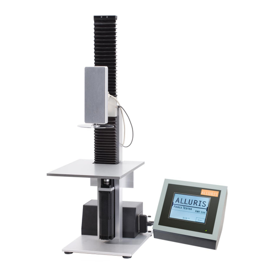
2.0 Overview over the components and the initiation The FMT-310 Force Tester consists of two base units, the motorised test stand (1) with integrated load cell (2) and the control unit (3) with touchpanel (4) for the operation. -
Page 4: Engaging The Instrument And Preparating The Measurment
Connect now the control unit with the test stand by inserting and locking the 37-pol connector (11). Check if the two plug connections (9;10) for the position sensor (8) and the load cell are inserted. Connect now the power cable (12) and switch on the instrument. -
Page 5: Menustructure, Functions, Simbols And General Handling
4.0 Menustructure, functions, symbols and general handling The menu of the control is structured in a way that allows to return to the subordinated menu at any time by pressing the BACK-button (right above). You choose a submenu by pressing the appropriate button. -
Page 6: Navigationbuttons For Oaging And Change Of The Level Of The Menu
As far as possible, the arrangement of the buttons on the screen is identically. Consecutively the general construction is outlined: The headline gives the titel of the actually retrieved menu. In the footer date, time and the memory capacity (depending on the menu) and the number of the version get indicated. -
Page 7: Handling Arrows To Control The Test Stand
4.2.2. Handling arrows to control the test stand Guide Start Stop Acknowledgement key To guide upwards or downwards arrow By pressing this key you within the manual mode. acknowledge the indicated To initiate, abort or stopp ATTENTION: The same arrows, at process. -
Page 8: Path Measurment
5.1.2 Path measurement The whole traverse path (405mm) of the drive gets suspended in 1.687.500 steps. This corresponds to an intern resolution of 0,24µm, the change of the position in single steps gets indicated with a resolution of 0,01mm. As both the load cell and the machine itself get expanded or compressed under load, the absolute traverse deviates from the actual path on the measuring axle. -
Page 9: Regulation Of The Limits
5.2.2 Regulation of the limits The traverse path of the load cell can be limited within the machine and load cell determined maximum values. Therefore the submenu limits gets called in which you can regulate the values within the navigation bar. Advice ! i The limits regulated for the manual mode have no influence within the test programs. -
Page 10: Tare The Force And Path Indication
5.2.6 Tare the force and path indication All indicated values can be reset to 0 during stillstand of the drive. Thereby the internal data of the load cell and absolute position of the linear unit do not get tared. Therefore a reference path has to be effected. -
Page 11: Zero-Point-Search
5.3.3.1 Zero-Point-Search During the zero-point search the reletive zero points of the force measurment and the path measurment get sincronized. Herefore the load cell gets moved with a predefined speed till the adjacent force value exceeds 0,5 % of the par value of the load cell. After this the load cell gets driven back to the force-zero- point with a predefined speed and the path measurment gets tared. -
Page 12: Predefined Test Programms
5.3.4 Predefined test programms During a test run the relevant dates are indicated on the display. After the test has been finished, the stored values can be called with the help of the result-button. If the test procedure effects a diagramm record, too, the force/path curve of the list of readings can be indicated by the help of the diagramm-button. -
Page 13: Break Testing 1 - Diagramm
5.3.4.1 Break testing 1 - diagramm The test procedure serve to appraise the breaking force by pressing continuously at a uniform speed the measurment object, while the readings get recorded continuously with a frequenz of 100Hz and than saved in the result memory. The operation consists of following steps: 1. -
Page 14: Bend Testing - Path Depending
5.3.4.3 Bend testing – path depending The test programm serves to appraise the necessary pressure force at a uniform speed and a predefined stretch of way. 1. Research of the HOME position at the speed v Home 2. Movement with the speed v up to the position START directly above the object;... -
Page 15: Endurance Testing (Pressure) With Pressure-Force-Regulation
5.3.4.4 Endurance testing (Pressure) with pressure-force-regulation The measurment object gets comprimied with the help of the inspection process. Herefore a forceregulation gets switched on after the excess of a predetermined force. This regulation maintains the force value for a predetermined time, if neseccary by changing the position of the force gauge. 1. -
Page 16: Tow Testing 1 - Diagramm
5.3.4.5 Tow testing 1 - Diagramm The inspection process serves to appraise the tear-out force at a continuous tension at a uniform speed until the break of the measurment object. Substantially the single steps corrispond with the break testing 1. For tambling the samle there is another intermediate Stepp in which the force gauge can be positionated manually. -
Page 17: Strech Testing - Path Depending
5.3.4.7 Strech testing – path depending With the help of the Inspection process it’s possible to calculate the necessary tension force to effect a the predetermined elongation of a measurement object at a constant speed. Hereby the measurement values get recorded with a measurement range of 100 hz. 1. -
Page 18: Endurance Testing With Tension Force Regulation
5.3.4.8 Endurance testing with tension force regulation Substantially the inspection process corrisponds with the endurance testing with pressure force regulation. But for an easier clamping, a manual intermedia Stepp is inserted. Adjustable parameter for the test procedure Parameter Zulässiger Wertebereich Reference Min. -
Page 19: Service Functions
6.1.2 Password Categorical the servicefunctions are protected by a password. You can change these passwords and afterwards not even the Alluris-Service is able to access the servicefunctions without a direct interference into the firm ware. It’s possible to protect the parameters for the corrisponding inspection processes with a user-password, which you can change within the service-menu, too. -
Page 20: Calibration
12 month. If you prefer not to effect the calibration on your own, our on-site service or our calibration laboratory is always at your disposal. Please find more informations on www.alluris.de. Condition for the calibration is a test weight which complies with the international and national standards so that you can effect the load cell under regard of tools which may have been assembled. -
Page 21: Adjust Date And Time
7.0 Connection to the PC The Force Tester FMT-310 can be conected to the serial interface of a PC by the help of a 9-p D-Sub connection cable (Art.No.: 2054). In this way, by using the software programm FMT-Connect (Art.No.: FMT-972S) it is possible to transfer measurment date and analyze them in MSExcel. -
Page 22: Technical Data
You can order an adequate lubricating grease (Art.No.: FMT-9802) and a manual compactor with a fitting tube attachment (Art.No.: FMT-9803) on www.alluris.de . 9.2 Updates (Software) Software-Updates can be brought in via the seriell interface of a PC. It is advisable to save the all the date before initiating the update as it can happen that parameter sets and result list get canceld during the update. -
Page 23: Change Components
9.3. Change components The three principle components of the FMT-310 Force Tester are with each other compatible ancd can be swiched at any time. Please take care that the test stand is swiched off and the power cable has been removed. - Page 24 Instrument” and should not be disposed as unsorted municipal waste. You may return it to Alluris for recycling. For more information please contact our website www.alluris.de The compliance to the requirements of all relevant EEC directives is confirmed by the CE- marking of the product.
- Page 25 Service Adressen: Alluris GmbH & Co. KG Technischer Service Basler Strasse 63 DE 79100 Freiburg | Deutschland Fon: +49 (0)761 47979 3 Fax: +49 (0)761 47979 44 service@alluris.de www.alluris.de...
Need help?
Do you have a question about the FMT-310 and is the answer not in the manual?
Questions and answers