
Related Manuals for Penlon AV-S


Summary of Contents for Penlon AV-S
- Page 1 Draft Copy July 2005 No update will be given AV-S Ventilator Remote Display Module and Interface for use with A200SP Absorber Service Manual Partnership for Life...
- Page 2 THE IMPORTANCE OF PATIENT MONITORING WARNING Anaesthesia system monitors and patient monitors are very desirable aids for the anaesthetist but are not true clinical Anaesthetic systems have the capability monitors as the condition of the patient is to deliver mixtures of gases and vapours also dependent on his respiration and the to the patient which could cause injury or functioning of his cardio-vascular system.
- Page 3 Annual / 2 Year / four year service including component replacement. Details of these operations are given in this Manual for the AV-S, available only for Penlon trained engineers. For any enquiry regarding the servicing repair of this product, contact the nearest...
- Page 4 Anaesthesia Ventilator. Information contained in this manual is correct at the date of publication. The policy of Penlon Limited is one of continued improvement to its products. Because of this policy, Penlon Limited reserves the right to make any changes which may affect instructions in this manual, without giving prior notice.
-
Page 5: Table Of Contents
CONTENTS Page No. USER RESPONSIBILITY ........WARNINGS AND CAUTIONS . - Page 6 CONTENTS PRE-OPERATION PROCEDURES Ventilator Set-up ..........5.1.1 Mounting the Ventilator .
-
Page 7: User Responsibility
Penlon or its appointed agents. USA and Canadian Federal Law restricts the sale and use of this device to, or on the order... - Page 8 The driving gas supply must be clean been approved and authorised by prevent ventilator Penlon for use with AV-S should be malfunction. employed. Do not use conductive breathing This ventilator is designed to be driven system hoses.
- Page 9 To assist the maintenance of the Using the Ventilator delivered patient tidal volume, the ventilator control system software includes: The AV-S ventilator is not intended for compliance compensation use in intensive care applications. algorithm, fresh compensation This apparatus must not be used with, algorithm.
-
Page 10: Warnings And Cautions
WARNINGS AND CAUTIONS The High and Low Airway Pressure Check that the cable between the Alarms are important for patient care. control unit and remote display screen It is important that the sensor is unit is connected before use. properly located in the expiratory limb Always use a cable type recommended of the circuit - refer to section 5.1.10. - Page 11 WARNINGS AND CAUTIONS CAUTIONS Circuit compliance is not activated until Fresh Gas Compensation is switched OFF. Do not sterilise the ventilator control unit. The patient block assembly must be removed from the control unit before sterilisation ( see section 6.2.4). NOTES All other internal components are not compatible with sterilisation techniques...
- Page 12 WARNINGS AND CAUTIONS - Oxygen Monitor Oxygen Monitor NOTES The O2 SENSOR FAULT alarm indicates WARNINGS that one of the following conditions has We recommend calibration of the occurred. oxygen monitor every time the system a) Internal electrical fault is turned on, as a safety precaution. b) Software/electronics fault c) Oxygen sensor fault.
-
Page 13: Purpose
The ventilator is intended for use by health care providers, i.e. Physicians, Nurses and Technicians with patients during general anaesthesia. The AV-S ventilator is not intended for use in intensive care applications. Oxygen Monitor Oxygen Monitor intended... -
Page 14: Description 3.1 General
3. DESCRIPTION AV-S Ventilator General Description Patient Monitoring Airway pressure, measured from the The AV-S Ventilator is a pneumatically expiratory limb of the breathing circuit. driven, software controlled, multi-mode Tidal volume Minute Volume ventilator. measurement is provided by a dual... -
Page 15: Description
A paediatric bellows assembly is available as an option Mounting options The AV-S integral screen and control unit can be mounted securely on the anaesthetic machine shelf or side bracket. Drive gas supply The supply must be at 310 to 689 kPa (45 to 100 psi ). - Page 16 13. VGA 14. Printer port Electrical Connection Electrical mains input and fuse unit 15. RS232 NOTE USB port is for use by Penlon-trained engineers only. All other data ports are read only. For further information, please contact Penlon Technical Support.
-
Page 17: Ventilation Cycle
DESCRIPTION Ventilation Cycle This section provides a simplified description of the ventilation cycle. Inspiratory Phase The inspiratory proportional valve (1) in the control unit opens, and bellows drive gas is delivered to the bellows housing (2). The expiratory proportional valve (3) opens and gas flows through the bleed valve. - Page 18 DESCRIPTION End of Expiratory Phase With the bellows at the top of its housing fresh gas continues to flow. prevent a high pressure build up the exhalation diaphragm (5) lifts and allows gas to exit through the exhaust valve (4). PEEP Positive End Expiratory...
- Page 19 DESCRIPTION Pneumatic Flow Diagram 3 to 7 bar 241 kPa (35 psi) 0 - 80 cmH 0 - 90 cmH 100 cmH...
-
Page 20: Pneumatic System
B) Pneumatic Control Manifold Block A) Gas inlet manifold block Inspiratory Proportional Valve The AV-S Ventilator is designed to operate on a 310 - 689 kPa (45 -100 psi) drive gas supply (oxygen or air - to customer’s requirement). Flow Sensor... -
Page 21: Electrical System
DESCRIPTION Electrical System Mains Supply mains supply inlet is designed for connection to any mains voltage from 100 to 240 VAC and a frequency of 50 to 60 Hz, without any adjustment. The connector is a standard IEC type. Back-up Battery In the event of mains electrical failure, the back- up battery cuts in automatically. -
Page 22: Control Panel
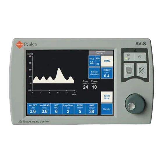
DESCRIPTION AV-S Gas Mixture cm H2O + air SMMV Trigger Freeze cmH2O Waveform -1.0 Pmax Pmean cmH2O cmH2O Spont Mode secs V m SET LIMIT PEEP V m MEAS Insp Time Standby cmH 2 O cmH 2 O Litres Litres... -
Page 23: Operational Capability
DESCRIPTION 3.5.2 User Adjustable Parameters Tidal Volume Range 20 - 1600 ml Rate 4 - 100 bpm I:E Ratio 1:0.3 to 1:8 PEEP 4 - 30 cmH2O Can be set to OFF Pressure Limit Volume mode: 10 - 80 cmH2O Pressure mode: 10 - 70 cmH2O 3.5.3 Operational Capability... -
Page 24: Output Compensation Functions
DESCRIPTION 3.5.4 Output Compensation Functions WARNING The AV-S automatically compensates for fresh (spirometry On), fresh mixture (spirometry and oxygen monitor On), and altitude. However, the actual tidal volume delivered to the patient may be different to the ventilation parameters set by the user, due to:... - Page 25 DESCRIPTION Interface to Prima SP2/3 and A200SP The AV-S is designed to interface with the Prima SP Anaesthetic Machine and the A200SP Absorber. 3.6.1 Prima SP Interface The interface cable links the socket (A) on the control panel to a socket on the rear panel of the anaesthetic machine.
-
Page 26: Ventilation Modes
DESCRIPTION Ventilation Modes 3.7.1 Standby Mode Allows parameters to be set. Some patient alarms are active: High airway pressure (at 80 cmH2O) High/Low O2 Negative pressure Incorrect Rate/Ratio... -
Page 27: Volume Mode
DESCRIPTION 3.7.2 Volume Mode Volume Mode Parameters The ventilator delivers a mandatory set volume of gas at preset, fixed breath Tidal volume 20 – 1600 mL intervals. Rate 4 – 100 bpm The Patient is making no respiratory effort. I:E ratio 1:0.3 –... -
Page 28: Pressure Mode
DESCRIPTION 3.7.3 Pressure Mode 3.7.3.1 Parameters The ventilator delivers a volume of gas to achieve a set pressure at fixed breath intervals. The Patient is making no respiratory effort. This is a common mode for the ventilation of small paediatric patients. Inspiratory pressure 10 - 70 cmH2O Rate... -
Page 29: Spontaneous Mode
DESCRIPTION 3.7.4 Spontaneous Mode 3.7.4.1 Parameters The ventilator monitors the following patient parameters: Rate I:E ratio Pressure Tidal volume Provides waveform displays Inspiratory oxygen is measured 3.7.4.2 Spontaneous mode operating functions No mechanical ventilation No Inspiratory Pause function Patient Monitoring (Bag mode and Ventilator mode): Airway pressures FiO2, Rate... - Page 30 DESCRIPTION 3.7.5 Advanced Spontaneous Breathing Modes 3.7.5.1 SIMV Synchronised Intermittent Pmax Mandatory Ventilation Guarantees a minimum level of volume. SIMV allows spontaneous breaths and a set mandatory breath PEEP 0 cmH SIMV Spontaneously Breathing Patient Inspiratory flow in the Trigger Window (generated by the patient’s spontaneous SIMV - Spontaneously Breathing Patient A = Cycle Time (set from BPM)
- Page 31 DESCRIPTION 3.7.5.2 SMMV Synchronised Mandatory Minute Ventilation Pmax Guarantees a set level of minute volume ventilation. SMMV allows spontaneous breaths, combined with a PEEP synchronised mandatory breath, to achieve the set minute volume 0 cmH SMMV - Spontaneously Breathing Patient SMMV - Spontaneously Breathing Patient Inspiratory flow in the Trigger Window A = Cycle Time (set from BPM)
-
Page 32: Psv Pressure Supported Ventilation
DESCRIPTION 3.7.5.3 Pressure Supported Ventilation PSV assists each spontaneous breath to achieve a preset pressure, thus reducing the effort required to breathe Inspiratory flow (generated by the PEEP patient’s spontaneous breath) results in synchronised 0 cmH pressure support PSV is used to support spontaneously breathing patients ONLY PSV Pressure Supported Ventilation... -
Page 33: Peep ( Positive End Expiratory Pressure)
DESCRIPTION 3.7.5.4 PEEP ( Positive End Expiratory Pressure) The AV-S ventilator includes a microprocessor- controlled, electronically integrated PEEP system, regulated using secondary pressure on exhaust diaphragm. The ventilator controls PEEP by allowing flow from, or delivering flow into the bellows drive circuit, maintaining... -
Page 34: On-Screen Menus
DESCRIPTION On-Screen Menus To Access: Press the menu switch on the front panel to access the following functions and parameters via drop-down menus: EXIT MENUS O2 MONITOR & SPIROMETRY FRESH GAS COMPENSATION: ON SPECIAL MODES Menu Switch WAVEFORM ALARM SETTINGS GAS MIXTURE: O2+AIR USER SETTINGS SERVICE MENU... -
Page 35: Spirometry
DESCRIPTION Spirometry Spirometry can be enabled, or disabled via the on-screen menu system. NOTE If the spirometry system is turned OFF: a) Fresh gas / fresh gas mixture compensation is disabled. b) Special Modes are disabled. See Appendix 3, for a detailed description of the spirometry system. -
Page 36: Alarms
DESCRIPTION 3.11 Alarms... -
Page 37: Oxygen Monitor
Bacterial Filter Use a breathing system bacterial filter in the expiratory limb of the breathing circuit to protect the oxygen sensor (see section 5 in the AV900 or AV-S user manual). CAUTION Replacement/Disposal - always follow the instructions supplied with the filter, and always replace at the recommended interval. -
Page 38: Menus
DESCRIPTION 3.12.3 Monitor sub-menu Monitor sub-menu ON/OFF Turn the navigator wheel to switch between O2 Monitor & Spiro ON and OFF. Press to confirm. ESCAPE FROM MENU Scroll to EXIT MENUS and press the wheel > O2 MONITOR: on to exit. CALIBRATION: 100% HIGH ALARM SET: 105 NOTE... -
Page 39: Display
DESCRIPTION - O Monitor 3.12.4 Display High Alarm Set Value High-set, low-set, and oxygen concentration percentage readings are displayed on screen. Touch the tab to activate O2 menu Oxygen Concentration The display provides a direct readout of measured oxygen concentrations in the range 0-100%. -
Page 40: Alarms
4. SPECIFICATION 4.1 Application Ventilation for use in anaesthesia. 4.2 Internal Compliance Adult bellows 3 ml/cmH O (nominal) Paediatric bellows 2 ml/cmH O (nominal) 4.3 Physical Size (mm) - control unit only 290 wide x 300 deep x 185 high - with adult bellows 290 wide x 300 deep x 385 high Screen Size... - Page 41 SPECIFICATION 4.5 Functional Tidal Volume Adult bellows 20 to 1600 ml (±10%) Paediatric bellows 20 to 350 ml (±10%) At ambient temperature of 20 o C (+/-10%) and ambient atmosphere of 101.3 kPa (+/-10%) Minute Volume 0 to 30 L Rate 4 - 100 bpm I:E Ratio...
- Page 42 SPECIFICATION 4.6 Advanced Spontaneous Breathing Modes (SIMV, SMMV, PSV) Trigger (PEEP Referenced) 0.2 to 4 L/min Trigger Window Set 60% of Expiratory Time Vt and Vm As Volume Mode Insp Time (Ti) 0.5 to 5 secs Support Pressure 3 to 20 cmH Default settings Volume Pmax...
- Page 43 SPECIFICATION Monitor 4.15 Oxygen Monitor Measurement Range: 0-l00% Resolution: ±1% Accuracy and Linearity: ±2% of full scale (at constant temperature and pressure) Response Time: 90% of final value in approx. 10 seconds (air to 100% O Operating Temperature: 50°F to 100°F (10°C to 38°C) Storage Temperature: 23°F to 122°F (-5°C to 50°C) Relative Humidity Range:...
- Page 44 SPECIFICATION Monitor Oxygen Monitor - continued Humidity Effects Sensor output is relatively unaffected by prolonged operation in either high or very low relative humidity. If the sensor shows signs of being affected by condensation, dry the sensor with soft tissue. CAUTION DO NOT use heat to dry the sensor.
-
Page 45: Ventilator
The following page contains a schematic 5.1.2 Electrical Power Connection diagram showing the cables and tubing for an AV-S ventilator mounted on a Prima SP Before connecting the ventilator to the mains anaesthetic machine with an integral A200SP supply, check that the power supply is within Absorber. - Page 46 PRE-OPERATION PROCEDURES Hoses and Cables Schematic AV-S and A200SP Absorber Note 1. AV-S has spirometry and oxygen monitor. 2. Interface cabling is shown for Prima SP2 On/Off switch and A200SP Bag/Vent switch.
- Page 47 PRE-OPERATION PROCEDURES Bellows Ventilator Control Unit Outlets to Anaesthetic Gas Scavenging System (AGSS) Bacterial Filter Absorber valve block Heat and moisture exchanger Patient CGO Block on anaesthetic machine (Fresh Gas Supply) Auxiliary Outlet on anaesthetic machine (Drive Gas Supply) Flow sensor - expiratory Flow sensor - inspiratory Connectors - sensor - pressure monitor Expiratory Valve - Absorber...
-
Page 48: Bellows Drive Gas
13. VGA 14. Printer port Electrical Connection Electrical mains input and fuse unit 15. RS232 NOTE USB port is for use by Penlon-trained engineers only. All other data ports are read only. For further information, please contact Penlon Technical Support. -
Page 49: Anaesthetic Gas Scavenging System
(labelled: DRIVE GAS) and the outlet (1) at the rear of the A200SP absorber. All other AV-S configurations: Connect a 16 mm diameter corrugated hose between the control unit drive gas outlet (labelled: DRIVE GAS) and the bellows base DRIVE GAS inlet port. -
Page 50: Breathing System
PRE-OPERATION PROCEDURES 5.1.9 Breathing System Connect the ventilator bellows base BREATHING SYSTEM port to the breathing system. a) Use a breathing system bacterial filter in the expiratory limb of the breathing circuit to protect the oxygen sensor. Use a heat and moisture exchanger (HME) at the patient Y piece. - Page 51 Delivery on/off switch. This will stop all gas flows (including the AHD basal flow). This will also turn the AV-S off. Turn the AV-S on at the ventilator (Do not use the Prima SP Gas Delivery switch). Disconnect the fresh gas hose from the CGO block on the anaesthetic machine.
-
Page 52: Pressure Monitor Connections
PATIENT PRESSURE port (A) on the rear panel of the control unit: Use the appropriate Penlon tubing assembly to connect to the expiratory limb of the breathing system, close to the circle system expiratory valve. -
Page 53: Bellows Assembly
Function test the ventilator - section Function test the ventilator - section 5.3.1. 5.3.1. NOTE If there is any malfunction, the ventilator must NOT be used. If the problem cannot be rectified, the ventilator must be checked by a Penlon trained engineer. -
Page 54: Pre-Use Checklists
PRE-OPERATION PROCEDURES Pre-use Checklist 5.2.1 Daily Checklist The following tests must be carried out at the beginning of every working day: Alarm System WARNING The operation of each alarm function should be verified daily. If the audible alarm or the visual display for any alarm function fails to activate during any alarm condition or fails to reset after the alarm has been cleared, refer the unit to an authorised service technician. -
Page 55: Function Test
NOT be used. patient connection as a test lung. If the problem cannot be rectified, the ventilator must be checked by a Penlon trained engineer. Adult bellows only: Set the tidal VOLUME to 600 ml; RATE to 10 bpm, and I:E RATIO to 1:2.0. -
Page 56: Weekly Checklist
If there is any malfunction, the ventilator must NOT be used. If the problem cannot be rectified, the ventilator must be checked by a Penlon trained engineer. Bellows Check the condition of the bellows and exhalation diaphragm valve - see section... -
Page 57: Installation
Installation Fit the probe (A) to the A200SP absorber. Connect the cable to the input socket (B) on the back of the AV-S ventilator control unit NOTE The anaesthetic machine gas control switch must be in the ON position for gas delivery. -
Page 58: Calibration
PRE-OPERATION PROCEDURES - O Monitor 5.3.2.1 Calibration - Using 100% Oxygen AV-S ventilator mounted on a Prima SP anaesthetic machine fitted with a A200SP absorber Calibrate with the sensor in position within the absorber. Detach the absorbent canister (1). Remove the breathing circuit hoses from the inspiratory and expiratory connectors (2) on the absorber. -
Page 59: Sensor Low Indication
PRE-OPERATION PROCEDURES - O Monitor 5.3.3 Sensor Low Indication The unit automatically detects when sensor O2 Monitor & Spiro life is low. The message: ESCAPE FROM MENU OXYGEN SENSOR LOW OUTPUT O2 MONITOR: on will appear on screen to indicate that the CALIBRATION: 100% sensor must be replaced. -
Page 60: Service Procedures
6. SERVICE PROCEDURES Service Intervals At 6 months, 12 months, 2 years and 4 years, the ventilator must be serviced by a Penlon-trained engineer, following the schedule given below, and the procedures given in section 7 in this Service Manual. Every day:... -
Page 61: Control Unit Patient Block Removal
SERVICE PROCEDURES Control Unit Patient Block Assembly - Removal On a regular basis (in line with hospital procedures for infection control), the patient block (1) must be removed, cleaned and sterilised. Detach the hoses from the outlets (2). Note different diameters for correct refitment. -
Page 62: Service Schedule
Select 'Upgrade Menu' check software revisions I/O Firmware for the main board Main Firmware for CPU core Select 'Ambient Pressure' Check reading is correct adjust as necessary by selecting 'Engineer Menu' - 'Penlon Options Menu' - 'Cal Pressure' Adjust to correct value. -
Page 63: Service Schedule
SERVICE SCHEDULE Engineer Error Codes (every six months) Select 'Service Menu' - 'Engineer Menu' - 'Diagnosis Menu'- 'Display Error Log' Check and investigate errors. Up to 30 Error Codes can be stored. Format is: Date - Time - Fault Example: 08/05/01 - 09:12:40 - On/Off Valve Reset Error log. - Page 64 SERVICE SCHEDULE Use an inflation bulb to apply pressure to the drive gas connector. Pressure should relieve at 100 cmH2O ± 10% Replace diaphragm valve and Non-return valve (every 12 months) Replace 5 mm, 7 mm, and 12 mm probe O-rings (every 12 months) Remove the 5mm hexagonal fitting at the rear of the control unit.
- Page 65 SERVICE SCHEDULE Connect the pressure tube to 'Patient Pressure' connection on the rear panel of the control module to the Pressure Sensing port on the rear of the absorber. Connect the cable from the 'Interface' connector on the rear panel of the control module and to the Spirometer connection on the rear of the absorber and the rear of the Prima SP anaesthesia.
- Page 66 SERVICE SCHEDULE lower or higher than reading on ventilator O2 display respectively. Return alarm levels to original settings. 11.9 Restore ventilator O2 sensor to correct location. Remove test O2 analyser. Refit canister. Spirometer Calibration (every 6 months) 12.1 Check condition of external Spirometer cables and connections. 12.2 Disconnect fresh gas hose from anaesthesia machine Common Gas Outlet.
- Page 67 SERVICE SCHEDULE Re-select 'Spont Mode' and select 'SIMV' NB: If absorber switch is not enabled in service menu, message will read 'Absorber in vent mode?' Press 'SIMV' once again. 13.8 Operate Test Lung very gently (by hand) Check that occasional ventilator assistance is given. 13.9 Stop operation of test lung.
- Page 68 SERVICE SCHEDULE 14.8 Apply a flow of Oxygen from Anaesthetic Machine of 8 L/min. Check displayed 'Vt Meas' Rises. 14.9 From Menus select Fresh Gas compensation ON. Allow 2 minutes for reading to stabilise. Check displayed 'Vt Meas.' = 600 ml +/- 50 ml. Observe that the bellows delivers less gas than before 14.10 Press 'Wave Freeze' Check waveform freezes on display.
- Page 69 SERVICE SCHEDULE Check that the 'AC Power Fail' alarm is displayed. Reconnect Mains lead to ventilator. 15.7 Remove drive gas line from gas supply pressure. Check 'Low Supply Pressure' alarm activates. 15.8 Re-connect drive gas line and ensure alarm clears. Pressure Ventilation (every 6 months) 16.1 Switch Ventilator to 'Pressure'...
-
Page 70: Parts Lists
8. PARTS LIST Preventive Maintenance Kits One year Kit Part No 57298 Exhaust diaphragm 300580 One-way valve 300581 O-rings (x 5) 5 mm - 041204 7 mm - 041245 12 mm - 041222 Inlet filter 300560 Bellows 57550 2 year Kit Part No 57299 As One year kit, plus: 12v battery... -
Page 71: Assemblies
PARTS LIST 5000492 Arm Assembly Control Unit and Remote Display Screen Assemblies Item Part No. Description Quantity 01056 M5 x 12 SKT HD Cap Screw 300529 Screen Display Assembly (Remote) 5000543 Chassis Assembly (Remote) 01130 M5 X 16 SKT Cap Head Screw ST STL 300549 Interface Cable - screen to control unit (not shown) - Page 72 PARTS LIST Display Screen Assembly Item Part No. Description Quantity 300540 Front Moulding 300541 Rear Cover 300575 Spinner Ø38 mm 300573 Gasket 01253 M4 X 25 SKT HD Cap 300550 Membrane Switch + LED’s 019122 M3 X 6 LG Button HD 300516 LVDS Encoder Assembly 01013...
- Page 73 PARTS LIST Screen Assembly (300524) Item Part No. Description Quantity 300565 8.4” TFT Screen (NEC) 300531 TFT Mounting Plate 300567 Inverter 5V 300599 M2.5 X 16 Butt HD SS 5000544 M2.5 Nyloc Nut ST STL 300536 Tape (Touch Screen To TFT) 300537 Tape (TFT To Plate) 300566...
- Page 74 PARTS LIST Control Unit Assembly (5000453) Item Part No. Description Quantity 01056 M5 x 12 SKT HD Cap Screw 300534 SP Mounting Plate 019171 M4 x 10 But Flanged HD 300564 Short Form Instructions 019049 M3 X 10 LG Pan HD 5000489 Chassis Assembly 5000499...
- Page 75 PARTS LIST...
- Page 76 PARTS LIST Control Unit Chassis Assembly (5000489) Item Part No. Description Quantity 5000459 Chassis - AVS 5000156 Regulator & Control Assembly 300595 DISS Con’ Nut 011240 Rubber Foot 01235 M8 Internal Star 01149 M8 Locknut 103996 Battery 104715 LEC Mains Connector / Filter 2220-099 LEC Mains Plug Retainer Assembly 5000449...
- Page 78 PARTS LIST...
- Page 79 PARTS LIST Regulator Assembly and Control Block Assembly Item Part No. Description Quantity 300526 Regulator Assembly 5000482 Control Block Assembly 019037 M3 X 35 Cap HD 041221 ‘O’ Ring Ø8.1 X Ø1.6...
- Page 80 PARTS LIST Patient Block Assembly Item Part No. Description Quantity 300580 Diaphragm 300581 One-way valve 300583 Inline Relief Valve 5000478 Check Valve Cap 300593 Taper Adaptor 300594 Tapered Conn 5000448 Spring Guide 5000450 Valve Body 5000451 Seat Insert 5000452 Drive Gas Block 5000453 Valve Base 0501...
- Page 81 PARTS LIST...
- Page 82 7. APPENDIX APPENDIX 1 Care of Back-up Battery CAUTION Damage may occur if the battery is allowed to remain in a discharged state. Never discharge the battery to below 10.2 volts. A. Battery installed in ventilator The battery must be charged before the machine is released for use with an 14 hour charge from the ventilator’s internal power supply (ventilator connected to the mains supply, but not running).
- Page 83 APPENDIX APPENDIX 2 On-screen Menus NOTE: All selection or changes in the menu are followed by a "CONFIRM" message prompt on the screen, and accompanied by a "BEEP" (user volume set) The selected text or option will invert in colour User settings menus only activate in Standby mode.
-
Page 84: Main Menu
Menu Structure O2 Monitor & Spirometry ESCAPE FROM MENU off / on (Toggle option O2 MONITOR: on 21 / 100% (Toggle option) CALIBRATION: 100% 19 -105 (Integer) HIGH ALARM SET: 105 18 - 99 (Integer) LOW ALARM SET: 18 off / on (Toggle option) SPIROMETER: on SPIRO CALIBRATION: 0 L/min... - Page 85 Service ESCAPE FROM MENU LANGUAGE: ENGLISH Language pick list PRINT PATIENT DATA ENGLISH SERIAL MODE: none ITALIANO CLOCK MENU TURKCE UPGRADE MENU POLSKI AMBIENT PRESSURE: 988 mBar ESPANOL DISPLAY HISTORY *SERVICE PIN: 0 Serial mode pick list *ENGINEER MENU NONE Philips SPACELABS Clock...
-
Page 86: Appendix
10 ms to the processor for calculation of the volume delivered to the Ventilator Spirometry Measurement patient. The AV-S ventilator drive gas and This delivered volume will consist of the spirometry system uses a total of three volume delivered from the ventilator bellows... - Page 87 APPENDIX near as possible, under the circumstances. Altitude Effects Accuracies for spirometry measurement are Gas flow measurements are also affected >300 ml ± 10% by atmospheric pressure, in a linear >100 ml <300 ml ± 20% relationship. <100 ml ± 50%. To compensate for altitude effects an ambient pressure sensor is available.
- Page 88 APPENDIX Dual Wheatstone bridges control airflow measurement - one provides closed loop heater control, the other contains the dual sensing elements. The heater circuit minimizes shift due to ambient temperature changes by providing an output proportional to mass flow. The circuit keeps the heater temperature at a constant differential (160°C) above ambient air temperature which is sensed by a heat-...
-
Page 89: Cleaning
APPENDIX APPENDIX 4 Cleaning Outside surfaces and bellows housing CAUTION Care must be taken not to allow liquids to run into the control unit; serious damage may result. Check that the unit is disconnected from the electrical supply before cleaning. Do not use cleaning solutions containing alcohol;... -
Page 90: Spirometer Sensors
APPENDIX Exhalation Diaphragm Valve The exhalation diaphragm valve is under the bellows and can be removed by loosening the three thumbscrews. The valve seat is now visible. WARNING Great care must be taken. Do not damage the precision surface of the valve seat (D). Never use any hard object or abrasive agent to clean it;... -
Page 91: Patient Connector Block
APPENDIX Sterilisation Recommended guidelines for sterilisation CAUTION To prevent possible damage to components, peak sterilisation temperatures must not exceed : 54 o C (130 o F) for gas (ethylene oxide) or, 134 o C (275 o F) for steam autoclave. Low temperature autoclave is 121 o C Do not sterilise the ventilator control unit. -
Page 92: Oxygen Sensor Replacement
APPENDIX Oxygen Monitor Sensor - Cleaning / Disinfection / Sterilisation In case of contamination the sensor may be cleaned with distilled water and allowed to dry naturally. CAUTION The sensor is not suitable for sterilisation by steam or exposure to chemicals such as ethylene oxide or hydrogen peroxide. - Page 94 Doc No AV-S (USA) 0105U SM July 2005 Manufactured by: Penlon Limited Abingdon Science Park Barton Lane Abingdon OX14 3PH Technical Support Tel: 44 (0) 1235 547076 Fax: 44 (0) 1235 547062 E-mail: technicalsupport@penlon.co.uk International Sales Tel: +44 1235 547001...
Need help?
Do you have a question about the AV-S and is the answer not in the manual?
Questions and answers