Advertisement
Quick Links
Thank you for choosing FAST™ products; we are proud to be your manufacturer of choice. Please read this
instruction sheet carefully before beginning installation, and also take a moment to review the included limited
warranty information.
These instructions focus on the Standalone XIM™. Please refer to the original XIM™ instructions (Part
#FAST4-101) for general XIM™ information.
Standalone Modes
The XIM™ has three modes of Standalone operation.
1. Onboard – adjustments made with physical switches mounted directly on the XIM™ circuit board.
2. Remote – adjustments made through a small, handheld device intended to be used in the cockpit.
3. PC Software – adjustments made through a software package loaded on a laptop.
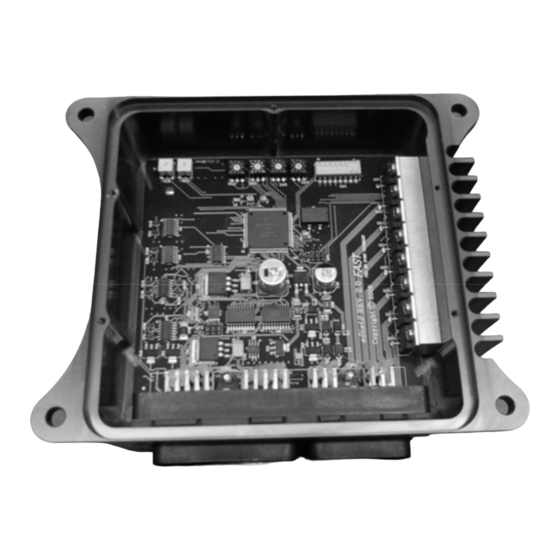
Onboard Switch Settings
The XIM™ is configured through a series of DIP switch settings. The switches are located under the back cover
of XIM™. To access the switches, simply take the lid off by removing the 5 screws, being careful not to tear the
gasket beneath the lid.
These example settings can be used to get up and running quickly. They are on the "safe" side. If desired, any of
the settings can be adjusted to suit the motor or application. More detail about each switch setting is given on the
following page.
Standalone XIM™
Quick Start Guide for Onboard Mode
FAST™
FAST™
3400 Democrat Rd.
3400 Democrat Rd.
Memphis, TN 38118
Memphis, TN 38118
Phone: (901) 260-3278 Fax: (901) 375-3408
Phone: (901) 260-3278 Fax: (901) 366-1807
www.fuelairspark.com
www.fuelairspark.com
INSTRUCTIONS
Part # FAST4-160
Part #???
Revised 11/30/09
Revised ??????
1
Advertisement

Related Manuals for Fast Standalone XIM

Summary of Contents for Fast Standalone XIM
- Page 1 INSTRUCTIONS Standalone XIM™ Thank you for choosing FAST™ products; we are proud to be your manufacturer of choice. Please read this instruction sheet carefully before beginning installation, and also take a moment to review the included limited warranty information. These instructions focus on the Standalone XIM™. Please refer to the original XIM™ instructions (Part #FAST4-101) for general XIM™...
- Page 2 GM Gen 4 / Gen 3 Cam 60-2 (1 pulse cam) 1 - 0 - 0 - 1 24 Pulse Dist. Plug 24X (Even, 1 cam) 50 - 60 FAST™ FAST™ 3400 Democrat Rd. 3400 Democrat Rd. Memphis, TN 38118 Memphis, TN 38118...
- Page 3 Timing Curve SW2, SW3 & SW5 are used to construct a base timing curve. SW3: Idle Timing SW2: Max Timing SW5: All-in RPM 1250 FAST™ FAST™ 3400 Democrat Rd. 3400 Democrat Rd. Memphis, TN 38118 Memphis, TN 38118 Part # FAST4-160...
-
Page 4: Manifold Pressure
Used to update firmware in XIM™.) Tach Output Pin 30-A3 is a 12V square wave tach output. It is available as a loose Brown/white wire and at pin F of the “CAM/HALL EFFECT” connector. FAST™ FAST™ 3400 Democrat Rd. 3400 Democrat Rd. - Page 5 Notes: 30-H1 EST Output A Purple See letters and numbers molded into sides of 30-H2 EST Output B Purple/White FAST™ FAST™ 3400 Democrat Rd. 3400 Democrat Rd. Memphis, TN 38118 Memphis, TN 38118 Part # FAST4-160 Part #??? Phone: (901) 260-3278 Fax: (901) 375-3408...
- Page 6 Blue Limited Warranty FAST, Inc. warrants that all of its products are free from defects in material and workmanship for a period of 1 year from the date of purchase. This limited warranty shall cover the original purchaser. FAST, Inc.’s obligation under this warranty is limited to the repair or replacement of its product. To make a warranty claim, the part must be returned within 1 year of purchase to the address listed below, freight prepaid.
Need help?
Do you have a question about the Standalone XIM and is the answer not in the manual?
Questions and answers