
Summary of Contents for Thermo Scientific CW3
- Page 1 Thermo Scientific CW3 Cell Washer Instruction Manual 50144259_h • 06 / 2018 Visit us online to register your warranty: www.thermofisher.com/labwarranty...
-
Page 4: Table Of Contents
4. 2. Operation Modes ............ 36 Thermo Scientific... - Page 5 Index ..............49 Thermo Scientific...
-
Page 6: Preface
Items Supplied 1. Preface 1. 1. Items Supplied Article No. Description Quantity Thermo Scientific CW3 cell washer S402776A Bowl Assembly S413259C Tank (5 L) 4744346 Tubing 75000015 Tube Connector S4011034 Drain Tube 2.5 m Test Tubes (12 mm in diameter and 75... - Page 7 Items Supplied Article No. Description Quantity Replacement Parts Rotor Assembly 75000022 24 places 75000023 12 places Distributor Assembly 75000024 24 places 75000025 12 places Thermo Scientific...
-
Page 8: Intended Use
1. 2. Intended Use The Thermo Scientific CW3 cell washer is designed to perform cell washing in multiple washing cycles using saline solution. The cell washer provides blood cells after sample separation, which can be used for further blood testing such as Antiglobulin test, ABO compatibility, Rh testing, Cross-matching and Antibody screening. - Page 9 While the rotor spins, never unlock the door. 10. Repairs, disassembly, and other modifications to the cell washer are strictly prohibited unless performed by a Thermo Fisher Scientific authorized sales/service representative. Thermo Scientific...
- Page 10 16. Depending on the magnitude, an earthquake might damage the cell washer. If you observe some abnormality, contact a Thermo Fisher Scientific authorized sales/service representative. N O TIC E Usually the control panel and the surface of the cell washer get warm during operation. Thermo Scientific...
-
Page 11: Symbols Used On The Cell Washer
This symbol demands to make sure, that the drain cover is installed in the cell washer door before you start the CW3 cell washer. If not, biological hazard is possible when contaminated samples are used. “5. 1. 4. 4. Drain Cover” on page 40 for removing and installation. -
Page 12: Symbols Used In The Manual
CAUTION means that material damage could occur. WARNING means that injuries or material damage or contamination could occur. This symbol refers to biological hazards. Observe the information contained in the instruction manual to keep yourself and your environment safe. Thermo Scientific... -
Page 13: Technical Specifications
Width 370 mm Depth 450 mm Weight ² 28 kg Front Side Measurement, 1 m in front of the instrument at 1.6 m height. 3 washing-cycles each with about 35 s centrifugation. Mode manual centrifuge Mode manual decant Thermo Scientific... -
Page 14: Directives And Standards
2. 2. Mains Supply The following table contains an overview of the electrical connection data. This data is to be taken into consideration, when selecting the mains connection socket. Unit Thermo Scientific CW3 cell washer Article No. 75007404 75007405 Mains Voltage... -
Page 15: Location And Function Of Parts
Rotates together with the rotor. It determines the angle to which the test-tube holders of the rotor swing. Door Test tubes are set on the rotor after opening the door. The drain cover and nozzle are installed on the back of the door. Thermo Scientific... -
Page 16: Rear View
Provided for supplying saline into the cell washer. Pump inlet connector To be connected to the saline tank by tubing. Door stopper parts Designed to keep the open angle (60°) of the door to prevent the door to be wide-open. Thermo Scientific... - Page 17 Location and Function of Parts Top view Part Decatation coil O-ring (2x) Rubber gasket Thermo Scientific...
-
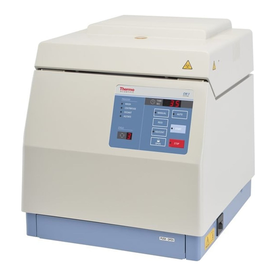
Page 18: Control Panel
TIME indicator Indicates the remaining time of centrifugation (in 3 digits). In case of an abnormality, the proper error code is shown. It also shows the rotor speed (×10 rpm) when PUSH SPEED on the condition-setting panel is pressed. Thermo Scientific... -
Page 19: Condition-Setting Panel
Operates only the first, second and the third cycles. Operates only the first, second, third and the fourth cycles. Operates only the first, second, third, fourth and the fifth cycles. 6 to 9 Selectable up to 9 in the same manner. Thermo Scientific... - Page 20 SALINE PRIME switch To be used for pump bleeding at the time of initial operation. The pump for saline supply operates while this switch is kept depressed. This switch is ineffective while the cell washer is in operation. Thermo Scientific...
-
Page 21: Transport And Set Up
21). Do not keep the rest of the one way packaging. Contact a shipping company or the customer service for the transport. Always remove the rotor before moving the cell washer. If you do not remove the rotor you might damage the cell washer drive or cell washer spindle. Thermo Scientific... -
Page 22: Leveling
3. 6. Setting Up NO T I CE Setting up the CW3 Cell Washer is easier when done by 2 people. 1. Install the motor guard plate Lift the front bottom of the cell washer. Put the two styropor pieces from the one way cell washer packaging below the cell washer feet. - Page 23 The buzzer stops as STOP is pressed or on its own after a short time. 5. Open lid Press OPEN and open the door. 6. Switch off cell washer Switch off the power supply switch. Thermo Scientific...
- Page 24 Remove the packagings from the rotor chamber. 8. Remove the drain cover Slide the pins in direction of the arrows at both sides. Pull the drain cover forward to remove it. 9. Remove the splash guard Remove the splash guard from the rotor chamber. Thermo Scientific...
- Page 25 Do this until the rubber gasket is in position as shown in the picture. Part Rubber gasket O-ring (2x) Decantation coil Magnet base Part Rubber gasket Magnet base If the rubber gasket is not in position, fluids can damage the cell washer. Thermo Scientific...
- Page 26 CAUTION When installing the drain cover, check that the nozzle at the center of the door is put through the hole of the drain cover. Install the drain cover correctly. 13. Install bowl Lightly apply silicone grease (483719) to the inner rim of the bowl and both o-rings of the decantation coil. Thermo Scientific...
- Page 27 Check that the bowl can be turned freely. If the bowl cannot be turned freely, the rubber gasket might not be mounted properly. Error message E14 or E16 might be displayed if the bowl is not installed correctly („Check rubber gasket“ on page 24). Thermo Scientific...
- Page 28 Setting Up Cross Section 1 – Flush 2 – Decantation coil 3 – Bowl 1 – Tube holder Detail View 1 – Bowl 4 – Bowl 2 – Flush 5 – Tube holder 3 – Decantation coil Thermo Scientific...
- Page 29 Turn the rotor about a quarter so that the coupling pins are inserted into the rotor shaft holes. Turn the top of the rotor clockwise and counterclockwise to check that the coupling pins are inserted into the rotor shaft holes (no free turn) after setting. Thermo Scientific...
- Page 30 CAUTION If the rotor is not set correctly, the rotor holder may come off the bowl and overswing. 15. Install distributor Set the distributor on the top of the rotor. Make sure that the coupling pins at the bottom of the distributor move in the holes at the top of the rotor. Thermo Scientific...
- Page 31 L-shaped adapter into the drain connector. Tighten it with the hose band (big). Hold the L-shaped adapter facing downward and connect it to the drain connector. If not waste liquid can stow and result in bad drainage. Thermo Scientific...
- Page 32 If it is not connected using the hose bands liquid can leak from the tube and might get inside of the cell washer. If the liquid might have leaked into the inside of the cell washer, contact a Thermo Fisher Scientific authorized sales/service representative for cleaning and drying the cell washer. Thermo Scientific...
-
Page 33: Storage
ƒ The cell washer must be clean and decontaminated. The decontamination must be confirmed in a decontamination certificate (“Decontamination Information ƒ Certificate” on page 45). Contact customer service for more details. ƒ Install the motor holder for shipping. Thermo Scientific... -
Page 34: Operation
Ventilation Adjustment of saline injection volume The CW3 cell washer is factory-adjusted to the injection volume of saline for use with the 24 place rotor and the 12 mm diameter test tubes. When using the 24 place rotor and 12 mm diameter test tubes with this cell washer, there is no need to adjust the injec- tion volume. - Page 35 Fill the saline tank with saline. Hold a beaker or other container to the nozzle. Press SALINE PRIME on the condi- tion-setting panel that is located at the front bottom of the device to discharge saline from the nozzle until no bubbles come out of the nozzle. Thermo Scientific...
-
Page 36: Setting The Operating Conditions
Centrifugation Use the 80% or less of the test tube capacity as sample volume for centrifugation. The tubes are centrifuged at an angle of 38.5°. 38.5° Centrifugal force Drive shaft Thermo Scientific... -
Page 37: Operation Modes
To stop the cell washer temporarily in the middle of a process, press STOP. For restarting the process, press START. Upon finish of the process The end buzzer sounds and START lights off. AGI/CENT lights up and the door is opened. Thermo Scientific... -
Page 38: Operational Sequence For Antiglobulin Test
The rotor spins about 5 seconds to collect the blood cells adhered to the wall surfaces of the test tubes at the bottom. This is done to ensure the reaction with the Antiglobulin reagent. This operation is performed at the end of the washing cycle. Thermo Scientific... -
Page 39: Maintenance
Information provided is to be considered as general guideline and may vary depending on the usage of the unit. If you use other cleaning methods than those described here, make sure that the necessary cleanliness is achieved according to your requriements. Thermo Scientific... -
Page 40: Pump, Tank And Tubing
CAUTION The distributor is made of polycarbonate. For cleaning make sure that you use washing solution (0.5% sodium hypochlorite solution) or the distributor might deteriorate. Use neutral detergent (pH 6 to 8). Do not dip the distributor in the diluted detergent solution for a long time or the strength of the distributor can decrease. Thermo Scientific... -
Page 41: Chamber, Splash Guard, Drain Cover And Door Stopper Parts
The rubber mount cracks or deteriorates. The door keeps being wide-open after you open the door. If the door keeps being wide-open, drops of waste liquid on the drain cover might fall on the rear of the cell washer. Thermo Scientific... -
Page 42: Preventive Maintenance
For the countries of the European Union the disposal is regulated by the European Union’s Waste Electrical & Electronic Equipment (WEEE) Directive 2002/96/EC. Mind the information on transport and shipping (“3. Transport and Set Up” on page “3. 8. Shipping” on page 32). Thermo Scientific... -
Page 43: Troubleshooting
Insert the attached allen wrench straight into the small hole and push it in until a click is heard. Then insert the allen wrench into the small hole of the other side in the same manner. The door unlocks and opens. Thermo Scientific... -
Page 44: Error Codes
Check if the rubber gasket and the bowl are installed correctly. „Check rubber gasket“ on page 24 „Install bowl“ on page 25. If the error still occurs, contact Thermo Fisher Scientific service. Others System error Contact Thermo Fisher Scientific service. Thermo Scientific... -
Page 45: Troublshooting When No Error Code Is Indicated
2. Sample is contaminated by bacteria. 2. Clean the tank, tube and pump (especially the inside of the tank). 3. Fragments of a test tube are mixed. 3. Remove glass fragments in the chamber and the drain cover. Thermo Scientific... -
Page 46: Decontamination Information Certificate
Decontamination Information Certificate Complete and attach to equipment BEFORE servicing. econtamination ertified itle osition hone ePArtment nstitution ddress tAte nstrument eriAl umBer otor eriAl umBer umBer AZArdous ontAminAnt eContAminAtion eContAminAtion ethod eContAminAtion ‘ ertifier ignAture Thermo Scientific... -
Page 47: Chemical Compatibility
Ater eXtrAn iethyl ther iethyl etone iethylPyro CArBonAte imethylsulfoXide ioXAne erriC hloride CetiC lACiAl (5%) CetiC (60%) CetiC thyl CetAte (50%) thyl lCohol (95%) thyl lCohol thylene iChloride thylene lyCol thylene Xide APor ™ iColl yPAque Thermo Scientific... - Page 48 (2%) odium ArBonAte odium odeCyl ulfAte (5%) odium yPoChlorite odium odide odium itrAte odium ulfAte odium ulfide odium ulfite iCKel Alts etroleum ther leiC XAliC (10%) erChloriC (70%) erChloriC (5%) henol (50%) henol Thermo Scientific...
- Page 49 NO T IC E Chemical resistance data is included only as a guide to product use. Because no organized chemical compatibility data exists for materials under the stress of centrifugation, when in doubt we recommend pretesting sample lots. Thermo Scientific...
-
Page 50: Index
Door Stopper Parts Drain Cover Tank Technical Specifications Transport Transporting Error Codes Troubleshooting Troublshooting Tubing Injection Volume Adjustment Intended Use Items Supplied Leveling Location Location and Function of Parts Mains Connection Mains Supply Maintenance Manual Mode Mechanical Emergency Door Release Thermo Scientific... -
Page 52: Instruction Manual
Thermo Electron LED GmbH Zweigniederlassung Osterode Am Kalkberg, 37520 Osterode am Harz Germany thermofisher.com/centrifuge © 2018 Thermo Fisher Scientific Inc. All rights reserved. Delrin, TEFLON, and Viton are registered trademarks of DuPont. Noryl is a registered trademark of SABIC. POLYCLEAR is a registered trademark of Hongye CO., Ltd.
Need help?
Do you have a question about the CW3 and is the answer not in the manual?
Questions and answers