Table of Contents
Advertisement
Quick Links
Download this manual
See also:
Reference Manual
Advertisement
Table of Contents

Subscribe to Our Youtube Channel
Related Manuals for ProSoft MVI56E-AFC

Summary of Contents for ProSoft MVI56E-AFC
- Page 1 MVI56E-AFC Enhanced Liquid and Gas Flow Computer for ControlLogix® v4.04 October 2, 2018 SETUP AND CONFIGURATION GUIDE...
-
Page 2: Your Feedback Please
® ProSoft Technology , is a registered copyright of ProSoft Technology, Inc. All other brand or product names are or may be trademarks of, and are used to identify products and services of, their respective owners. In an effort to conserve paper, ProSoft Technology no longer includes printed manuals with our product shipments. -
Page 3: Warnings
Shock: 30 g, operational; 50 g, non-operational; Vibration: 5 g from 10 Hz to 150 Hz Relative Humidity: 5% to 95% with no condensation All phase conductor sizes must be at least 1.3 mm(squared) and all earth ground conductors must be at least 4mm(squared). Agency Approvals and Certifications Please visit our website: www.prosoft-technology.com... -
Page 4: Table Of Contents
Contents MVI56E-AFC ♦ Version 4.04 Contents Your Feedback Please ......................2 Important Installation Instructions ..................2 MVI (Multi Vendor Interface) Modules ................. 2 Warnings ..........................3 Battery Life Advisory ......................3 Before You Begin ..................9 Pre-Configuration Processes ..................9 Pre-Configuration Requirements ................ - Page 5 MVI56E-AFC ♦ Version 4.04 Contents What Parameters Do I Have to Configure? ............. 47 Configuring Meter and Stream Identification Parameters ........48 Setting End of Period Parameters ..............49 Setting a Stream Name ..................51 Configuring Meter Type, Product Group, Units, and Primary Input ......52 Selecting and Configuring Meter Type, Product Group, Units and Primary Input Parameters ......................
- Page 6 Configuring Meter Factors..............101 Installing the Module in the Rack ............105 Module Initialization ....................105 Connecting the MVI56E-AFC to the EAFC Manager ......107 Downloading the Project to the MVI56E-AFC ........111 Creating a RSLogix Project and Importing an AOI ......113 Create an RSLogix Project ..................
- Page 7 MVI56E-AFC ♦ Version 4.04 Contents Meter Configuration ..................133 Stream Configuration ..................135 Meter Calculations .................... 136 Meter Accumulators ..................138 Meter Status ..................... 139 Data Displays ....................141 What’s Next? ..................143 Support, Service and Warranty ............145 Contacting Technical Support ................145 Warranty Information .....................
- Page 8 Contents MVI56E-AFC ♦ Version 4.04 Page 8 of 149 ProSoft Technology, Inc. October 2, 2018...
-
Page 9: Before You Begin
Before You Begin Pre-Configuration Processes This section describes the pre-configuration process. There are a small number of tasks to complete before configuring your MVI56E-AFC project. The following flow illustrates the full configuration process. ProSoft Technology, Inc. Page 9 of 149... -
Page 10: Pre-Configuration Requirements
Download EAFC Manager software Download the MVI56E-AFC Add-On Instructions (AOIs) Downloading EAFC Manager The EAFC Manager can be downloaded from the ProSoft Technology website. Navigate to the MVI56E-AFC webpage found here. Click on the D tab. OWNLOADS Click on the P... -
Page 11: Downloading Aois To Your System
MVI56E-AFC ♦ Version 4.04 Before you Begin Downloading AOIs to your system Navigate to the MVI56E-AFC webpage found here. Click on the D tab. OWNLOADS Select MVI56E-AFC A NSTRUCTIONS The AOIs are downloaded as a zip file. The zip file contains the Main AOI as well as four additional AOIs that pertain to your meter application. -
Page 12: Locating Information For Your Meter Type
MVI56E-AFC ♦ Version 4.04 Download the Main AOI and the AOI file that pertains to your meter type. For instance, if the MVI56E-AFC is going to be used for Differential Gas meter runs, you only need the MVI56E-AFC_MeterDifferentialGas_Vx_x.L5X file. You will use these files when you set up your RSLogix project later in this guide. - Page 13 MVI56E-AFC ♦ Version 4.04 Before you Begin To locate configuration information about your meter, refer to the following table: What type of meter What is the primary Configure your Configure your primary input as… are you output from your flow meter type as…...
-
Page 14: Configuration Aids
Before you Begin MVI56E-AFC ♦ Version 4.04 Configuration Aids This manual contains icons within each section. Each icon represents a relationship to the topic. Accumulator Alarm Back Calculate Calibrate Calibrate 2 Ethernet Event Export Flow Liquid Login Logout Meter Meter... - Page 15 MVI56E-AFC ♦ Version 4.04 Before you Begin Site Stream Temp User Delete User Add User Edit User View Delete View Add View Edit View Volume The icons are used as visual cues to provide a hint of the type of information contained within a section.
-
Page 16: Using The Modbus Dictionary
Before you Begin MVI56E-AFC ♦ Version 4.04 Using the Modbus Dictionary Important: Although this manual is continuously maintained to bring you the latest information, the Modbus Dictionary contains the latest information on registers and dictionary sections. It is recommended that you use the Modbus Dictionary to locate bank and register values to ensure that you are looking at the latest information. - Page 17 MVI56E-AFC ♦ Version 4.04 Before you Begin You can use the Modbus Dictionary locally or while EAFC manager is directly connected to the MVI56E-AFC. From the Source Configuration section, select if you are just running Modbus Dictionary locally or select O OCAL LINE connected to a module.
-
Page 18: Procedure
Before you Begin MVI56E-AFC ♦ Version 4.04 Procedure Ensure that you have a suitable project loaded, especially its version. This ensures that dictionary items present for your module are available for display. In EAFC Manager, select the P tab. ROJECT Select Modbus Dictionary, See Starting EAFC Manager for information on setting your module type. - Page 19 MVI56E-AFC ♦ Version 4.04 Before you Begin Click on the appropriate row. Once a row is selected, additional information is displayed at the bottom of the window. ProSoft Technology, Inc. Page 19 of 149 October 2, 2018...
- Page 20 Before you Begin MVI56E-AFC ♦ Version 4.04 Observe the Bank and Reg information in the first column. This column may contain a number of items with different representations. In the first row, the first position indicates whether the register is a Holding Register (H-) or an Input Register (I-), the second position represents the register (8000).
-
Page 21: Creating An Eafc Manager Project
Starting EAFC Manager Click S > P TART ROGRAMS From the Programs menu, choose P ECHNOLOGY From the ProSoft Technology folder, choose EAFC M ANAGER The EAFC Manager opens. Select F > N > MVI56E-AFC > MVI56E-AFC, 16 ). The METERS EAFC Manager project must match the firmware running on the EAFC. - Page 22 Creating an EAFC Manager Project MVI56E-AFC ♦ Version 4.04 Communications between the EAFC Manager and the MVI56E-AFC is not required during the configuration stage. However, you can establish communications at this point if you wish. Simply follow the instructions Chapter “Installing the Module in the...
-
Page 23: Configuring Site Parameters
Memory allocation Port configuration and mapping Site options and status You can also obtain the MVI56E-AFC firmware version from this window. Accessing Site Configuration Parameters From the Project menu, choose S ONFIGURATION ProSoft Technology, Inc. Page 23 of 149... - Page 24 This parameter allows an external application such as EAFC Manager to synchronize its database with the database resident in the module. Default is "MVI56E-AFC". If you plan on setting these parameters, please refer to the MVI56E- Primary and Virtual Modbus Slave Address AFC Reference Guide for additional details.
- Page 25 The calculation assumes that all meters measured by a single MVI56E-AFC are located at the same site and have the same barometric pressure. ProSoft Technology, Inc.
-
Page 26: Configuring Site Options
Configuring Site Parameters MVI56E-AFC ♦ Version 4.04 Configuring Site Options The Site Options dialog box opens when you click the S field in the PTIONS Site Configuration dialog box. Not all options are available unless other parameters and options are selected during the configuration process. -
Page 27: Configuring Pass-Thru Options
The Pass-Thru feature can be used for delivering data written by Modbus packets directly to the PLC logic, bypassing the MVI56E-AFC’s Modbus database. For details on configuring this option, please refer to the MVI56E-AFC Reference Guide. The module supports the Modbus Pass-Thru feature for write commands. When... -
Page 28: Udt Tag Prefix
Configuring Site Parameters MVI56E-AFC ♦ Version 4.04 UDT Tag Prefix Prefix for generated UDT names. UDT definition files generated for the AFC project, including those for backplane-return layouts and archive record layouts, may be imported into the RSLogix project. To avoid conflict with names of other... -
Page 29: Exporting Udt Files
MVI56E-AFC ♦ Version 4.04 Configuring Site Parameters Exporting UDT Files You can export UDT files through the Backplane Return window. Note: The backplane return window exports Backplane Return UDTs. Archive record layout UDTs are exported from the Archive Configuration Window (after saving the project). - Page 30 Configuring Site Parameters MVI56E-AFC ♦ Version 4.04 From the Dictionary section, select the UDT file files. This activates the button. NSERT Click the I button to add the file to the Process Input side of NSERT the page. When UDT files are inserted, the E...
-
Page 31: Setting Communication Parameters
MVI56E-AFC ♦ Version 4.04 Configuring Site Parameters Setting Communication Parameters ProSoft Technology, Inc. Page 31 of 149 October 2, 2018... - Page 32 Configuring Site Parameters MVI56E-AFC ♦ Version 4.04 Use to configure Modbus TCP/IP communication Communication settings. Serial 1 or Serial 2 Use Serial 1 or Serial 2 buttons to configure serial communication settings. Use Serial 2 to set up a Modbus Master.
-
Page 33: Configuring Modbus Tcp/Ip
MVI56E-AFC ♦ Version 4.04 Configuring Site Parameters Configuring Modbus TCP/IP You must configure the communication parameters for the Ethernet port using the EAFC Manager software (Site Configuration): ProSoft Technology, Inc. Page 33 of 149 October 2, 2018... - Page 34 Configuring Site Parameters MVI56E-AFC ♦ Version 4.04 Server Configuration The Server tabs allow you set different configurations for up to four servers. Page 34 of 149 ProSoft Technology, Inc. October 2, 2018...
- Page 35 MVI56E-AFC ♦ Version 4.04 Configuring Site Parameters The following process applies to each server: Step Task Description/Example Click on the tab of the server that you want to configure. Enable the server by clicking the Enabled checkbox. Configure the This field indicates the IP address of the physical interface in dotted network decimal format.
- Page 36 The effect of the AFC Slave option depends on Mode setting. If the device is set as End Device, then this option selects which of the two MVI56E-AFC slaves is to be the addressed end device. If the device is set to Gateway, then this option changes to a checkbox that hides the primary slave.
-
Page 37: Setting Whitelist Options
The relative positioning of non-empty entries is relevant however, as a later entry can override the effect of an earlier entry. See the MVI56E-AFC Reference Guide for detailed information. ProSoft Technology, Inc. Page 37 of 149... -
Page 38: Advanced Tab
Configuring Site Parameters MVI56E-AFC ♦ Version 4.04 Advanced Tab Overall Settings Parameter Description Keepalive idle time This setting enables a network server to free up resources allocated to broken connections. The three settings are: Idle time Probe interval ... - Page 39 MVI56E-AFC ♦ Version 4.04 Configuring Site Parameters Parameter Description A “probe” is a TCP/IP packet that asks the client “Are you still there?”. If the client answers any probe with “Yes, I’m still here”, then the connection is good. The client is merely silent and the server resets “keepalive” logic for another cycle.
-
Page 40: Configuring Serial 1 And Serial 2
Once configured, click R from the Site page to save changes. Configuring Serial 1 and Serial 2 The MVI56E-AFC contains two serial port connections. Serial 2 may be used as a Modbus Master. Serial Only The module supports the following communication parameters for each... - Page 41 MVI56E-AFC ♦ Version 4.04 Configuring Site Parameters You must configure the communication parameters for each communication port using the MVI56E-AFC Manager software (Site Configuration): ProSoft Technology, Inc. Page 41 of 149 October 2, 2018...
- Page 42 Configuring Site Parameters MVI56E-AFC ♦ Version 4.04 Port Options Option Description Modbus Master Enables the Modbus Master for the port (Serial 2). The Modbus Master command is generated from the processor using ladder logic (Modbus master block). After the Modbus Master transaction is completed the...
- Page 43 (Project > Site Configuration > Port X button). This feature requires ladder logic to read the pass-through block from the module to the processor. Refer to the Ladder Logic section in the MVI56E-AFC Reference Guide for more information about the pass- through feature. ProSoft Technology, Inc.
-
Page 44: Poll Button
Configuring Site Parameters MVI56E-AFC ♦ Version 4.04 Poll Button The function of the P button is to update the display of site status (the black- background boxes in the upper right quadrant of Site Configuration). Local Port Settings Dialog Box... -
Page 45: Read Button
MVI56E-AFC ♦ Version 4.04 Configuring Site Parameters Read Button The R button reads the current site configuration from the module to the local PC. Look at the result area (green rectangle) on the Site Configuration dialog box for the status of the read operation. When a "Success" indication shows in the result area, it indicates that the site configuration has been successfully read to the local PC. -
Page 46: Done Button
Manager, otherwise your configuration will be discarded. Remapping Button Refer to the MVI56E-AFC Reference Guide. Accessing the Data Information on accessing data is discussed in the MVI56E-AFC Reference Guide. Site Status Site status information is discussed in the MVI56E-AFC Reference Guide. -
Page 47: Configuring Meter Parameters
MVI56E-AFC ♦ Version 4.04 Configuring Meter Parameters Configuring Meter Parameters Prerequisites Ensure that all site information is configured as described in the previous chapters. What Parameters Do I Have to Configure? The Meter Configuration page allows you to configure your meter based on your application. -
Page 48: Configuring Meter And Stream Identification Parameters
Configuring Meter Parameters MVI56E-AFC ♦ Version 4.04 Configuring Meter and Stream Identification Parameters Identification Parameters identify the meter. Select the Meter number. Click the I button to display the Meter Identification window. DENTIFICATION Page 48 of 149 ProSoft Technology, Inc. -
Page 49: Setting End Of Period Parameters
MVI56E-AFC ♦ Version 4.04 Configuring Meter Parameters Add the following identifying parameters: General Type Manufacturer Model Serial Number Size Nominal K Factor Click OK when you are done. Repeat this for every configured meter. - Page 50 Configuring Meter Parameters MVI56E-AFC ♦ Version 4.04 Setting Precedence You can set the End-of-day minute and End-of-hour minute on the Site page as well. The parameters set on the site page represent a global setting and End of Period parameters set on the Meter Configuration are ignored. However, you can give the Meter setting precedence using the Meter Control Options dialog.
-
Page 51: Setting A Stream Name
MVI56E-AFC ♦ Version 4.04 Configuring Meter Parameters Sample rate alarming – This is the longest period that can elapse between successive fresh samples of process input values without raising the “sample rate too low” alarm. This value is specified in seconds with a range of 0 through 30. -
Page 52: Configuring Meter Type, Product Group, Units, And Primary Input
Configuring Meter Parameters MVI56E-AFC ♦ Version 4.04 Configuring Meter Type, Product Group, Units, and Primary Input These parameters must be configured before you configure any common or application detail parameters. What you select here affects the available parameters that must be configured for your application. -
Page 53: Selecting And Configuring Meter Type, Product Group, Units And Primary Input Parameters
MVI56E-AFC ♦ Version 4.04 Configuring Meter Parameters Selecting and Configuring Meter Type, Product Group, Units and Primary Input Parameters The following table helps you determine what Meter Type and Primary Input parameters must be entered in EAFC Manager based on the kind of meter you are configuring and the primary output of the meter and associated instrumentation. - Page 54 Configuring Meter Parameters MVI56E-AFC ♦ Version 4.04 Column 1 Column 2 Column 3 Column 4 Turbine Meter Pulse Count and Linear Pulse Count Pulse Frequency Pulse Frequency Linear Pulse Frequency Pulse Count Linear Pulse Count Positive Displacement Same as Turbine...
-
Page 55: Product Group
The Product Group represents what you are measuring (i.e., gas or liquid). The Product Group drop-down list allows you to select the appropriate Product Group for your application. Refer to the MVI56E-AFC Reference Guide for detailed information. Note: The Product Injected Meter Type feature produces an Accumulation Overflow error. The associated flow calculations will be invalid. -
Page 57: Configuring Common Parameters
MVI56E-AFC ♦ v4.04 Common Parameters Configuring Common Parameters Common parameters are common to all applications. These parameters are always visible and should be configured. ProSoft Technology, Inc. Page 57 of 149 October 2, 2018... -
Page 58: Selecting The Physical Device
Common Parameters MVI56E-AFC ♦ Version 4.04 Common parameters include: Physical Device Reference Conditions Accumulators and Flow Rates Process Input Control Options Backplane Return Calculation Options Resettable Accumulators Meter Factors Stream Options Selecting the Physical Device Select your device from the drop-down list. - Page 59 MVI56E-AFC ♦ Version 4.04 Common Parameters If you are using a differential gas type meter, measuring differential pressure, you have the option of selecting from the following standards: Orifice plate (AGA 3 [2012]) Orifice plate (AGA 3 [1992]) ...
-
Page 60: Specifying Reference Temperature And Pressure (Reference Conditions)
Common Parameters MVI56E-AFC ♦ Version 4.04 Specifying Reference Temperature and Pressure (Reference Conditions) Measurements of gas and liquids are calculated based on their characteristics at a specific temperature and atmospheric pressure. Specify the reference conditions in this area. The default values are 15°C/101.325 kPaa (SI) and 60°F/14.696psia (US), which are the standard API base conditions. -
Page 61: Setting Accumulators And Flow Rates
MVI56E-AFC ♦ Version 4.04 Common Parameters Setting Accumulators and Flow Rates Flow Rate Period Unit Click on the F box to change the flow rate period. LOW RATE PERIOD UNIT Flow Rate Unit Click on the F box to change the flow rate unit. -
Page 62: Accumulation Unit
Common Parameters MVI56E-AFC ♦ Version 4.04 Accumulation Unit Click on the A box to change volume accumulator units. CCUMULATOR UNIT Accumulator Rollover This is the value when mass accumulators are reset to zero and it 1 greater than the highest value that the accumulator may hold. -
Page 63: Configuring Process Input Scaling
If input data ROCESS NPUT is not within the configured range, the MVI56E-AFC will flag an alarm on the Meter Monitor dialog box (refer to Meter Monitor section) and the alarm bit for the meter is set. -
Page 64: Enabling/Disabling The Meter (Control Opts)
To retrieve the status of a meter, click the R button in the Meter Configuration area. Note: The meter can also be enabled or disabled from ladder logic (refer to the MVI56E-AFC Setup and Configuration Guide). Backplane Return There is at least one backplane function block that is repeatedly and frequently delivered from the processor (PLC) to the module. - Page 65 MVI56E-AFC ♦ Version 4.04 Common Parameters This provides the user with full functionality for the configuration of both backplane return blocks. The user is allowed to select desired values from the Modbus database which the module delivers to the PLC automatically and on a regular basis without having to create and issue a separate backplane transaction such as Modbus Gateway in order to retrieve those values.
-
Page 66: Configuring Calculation Options
ALCULATION dialog. Details on each option can be found in the Modbus Dictionary. Options that to not apply to the current application are grayed out. See Calculations Options in the MVI56E-AFC Reference Guide for detailed information. Page 66 of 149 ProSoft Technology, Inc. -
Page 67: Configuring Resettable Accumulators
MVI56E-AFC ♦ Version 4.04 Common Parameters Configuring Resettable Accumulators The MVI56E-AFC supports a total of 12 accumulators per meter channel, divided into the following categories: Non-Resettable Accumulators (6) Resettable Accumulators (4) Archive Accumulators (2) Click the R button. -
Page 68: Non-Resettable Accumulators
Common Parameters MVI56E-AFC ♦ Version 4.04 Non-Resettable Accumulators The non-resettable accumulators are only reset when the accumulator rollover value is reached. The accumulator rollover value, and the accumulator unit must be configured using the EAFC Manager. The module supports six non-resettable accumulators in order to show the measure quantity to be totalized. -
Page 69: Resettable Accumulators
MVI56E-AFC ♦ Version 4.04 Common Parameters Resettable Accumulators From the Resettable Accumulator Select window, click O PTIONS The resettable accumulators are referred to as: Resettable Accumulator 1 Resettable Accumulator 2 Resettable Accumulator 3 Resettable Accumulator 4 Resettable Accumulators are configured from the Resettable Accumulator Select dialog box. - Page 70 Common Parameters MVI56E-AFC ♦ Version 4.04 Each Resettable Accumulator can be configured to represent a different quantity as follows: Modbus address for accumulator Default Value Accumulator select (Meter-relative) Net (code 3) Resettable accumulator 1 Gross (code 4) Resettable accumulator 2...
- Page 71 MVI56E-AFC ♦ Version 4.04 Common Parameters The resettable accumulators are reset when one of the following situations occur. Resetting from EAFC Manager You may reset any of the resettable accumulators using the EAFC Manager (Meter Monitor): Resetting from Ladder Logic The ladder logic may send a meter signals block to command one or more resettable accumulators to be reset.
- Page 72 Common Parameters MVI56E-AFC ♦ Version 4.04 Resetting upon Archive Period End or Reset upon Event Use EAFC Manager to configure the resettable accumulator to be reset when the archive period ends or when an event occurs. Refer to Event Log in the MVI56E- AFC Reference Guide for more information on configuring and monitoring events.
- Page 73 MVI56E-AFC ♦ Version 4.04 Common Parameters Archive Accumulators The archive accumulators are part of the current archive (archive 0) data. These accumulators are automatically reset when a new archive is generated. Refer to the Modbus Dictionary – Meter Accumulator section.
-
Page 74: Net Accumulator Calculation
Common Parameters MVI56E-AFC ♦ Version 4.04 Net Accumulator Calculation The Net Accumulator Calculation depends on the product group (gas or liquid). For gas applications, the Net Accumulator is calculated as follows: Gross Accumulator Net Accumulator Converts to Reference Temperature and Pressure... -
Page 75: Accumulator Totalizer And Residue
MVI56E-AFC ♦ Version 4.04 Common Parameters Accumulator Totalizer and Residue The accumulators are expressed as the totalizer and residue parts. This implementation allows the accumulation of a wide range of increments, while keeping a high precision of fractional part with an approximately constant and small round off error. -
Page 76: Meter Alarm Control Options
Common Parameters MVI56E-AFC ♦ Version 4.04 Meter Alarm Control Options Click C from the Meter Configuration page. ONTROL PTIONS Bits 0 through 4 allow you to set up alarm configurations. Alarming Action Alarming: require If set, then any alarm appearing in the Meter Alarms, registers (I-30 through I- 37) must be manually acknowledged by writing a “1”... - Page 77 MVI56E-AFC ♦ Version 4.04 Common Parameters Alarming Action Alarming: If set, then the acknowledgement of any alarm requires that the Weights & Acknowledge Measures switch be in the "unlocked" position. If clear, then alarm action is sealable acknowledgement requires only that the acknowledging operator have the necessary permission ("Troubleshooting", permission bit 13).
-
Page 78: Setting Stream Options And Enabling/Disabling Meters
MVI56E-AFC Manager provides Page 78 of 149 ProSoft Technology, Inc. - Page 79 Modbus register, hense in exceptional circumstances it can be issued from anywhere, such as by a SCADA system connected to one of the Modbus ports or by the MVI56E-AFC Manager itself via the Modbus Master window. Parameters whose values may depend on the properties of the product being measured are configured for each stream separately.
- Page 80 Common Parameters MVI56E-AFC ♦ Version 4.04 Stream Option Definition Interpolate K-factor This option bit swaps the roles of K-factor and meter factor, so that when this option is selected, the "K-factor" entry becomes "Meter factor" and the "Meter Factor Linearization" table becomes "K-factor Linearization".
-
Page 81: Configuring Differential Meter Parameters
MVI56E-AFC ♦ Version 4.04 Differential Meter Parameters Configuring Differential Meter Parameters If Differential Meter is selected as the Meter Type, select either Differential Pressure or Flow Rate as the Primary input. ProSoft Technology, Inc. Page 81 of 149 October 2, 2018... - Page 82 Differential Meter Parameters MVI56E-AFC ♦ Version 4.04 If Differential Pressure is selected as the Primary Input, you must configure the following parameters: Parameter Description DP Flow Threshold If at any time the differential pressure input value is less than the DP Flow Threshold parameter, the module will treat the differential pressure as zero (no flow).
- Page 83 MVI56E-AFC ♦ Version 4.04 Differential Meter Parameters If you select Flow Rate as the primary input, you must configure the following parameter: FR Flow Threshold – If at any time, the flow rate value is less than the FR Flow Threshold parameter, the module will treat the flow rate as zero (no flow).
-
Page 85: Configuring Linear Meter Pulse Count Options
MVI56E-AFC ♦ Version 4.04 Gas Parameters Configuring Linear Meter Pulse Count Options If Linear Meter with Pulse Count is selected as the main Input parameter, you must configure the following parameters: ProSoft Technology, Inc. Page 85 of 149 October 2, 2018... - Page 86 Gas Parameters MVI56E-AFC ♦ Version 4.04 Parameter Description Frequency flow This is the threshold value for pulse frequency. If the received value is less than threshold the configured threshold, it is deemed to be zero. Pulse input When the meter is selected as a Pulse Meter, one of the input variables rollover transferred from the programmable logic controller is Pulse Count value.
-
Page 87: Configuring Linear Meter Pulse Frequency Options
MVI56E-AFC ♦ Version 4.04 Gas Parameters Configuring Linear Meter Pulse Frequency Options If Linear Meter Pulse Frequency is selected, you must configure the following parameters: Parameter Description Frequency Flow This is the threshold value for pulse frequency. Values can range Threshold between 0 and 1.0e+06 Hz. -
Page 88: Configuring Gas Parameters
Default relative Normally, the MVI56E-AFC uses the Detail Characterization Method of the density AGA 8 standard to calculate the density of the gas from its composition as given by the molar analysis. The density is used in all subsequent calculations. - Page 89 Default Fpv Normally, the MVI56E-AFC uses the Detail Characterization Method of the AGA 8 standard to calculate the compressibilities of the gas from its composition as given by the molar analysis. The compressibilities are used in all subsequent calculations.
- Page 90 Gas Parameters MVI56E-AFC ♦ Version 4.04 Parameter Description depend on the System of Units selected in the Meter Type, Product Group, and Units panel. A user can override the default heating value. In order to do so, you must enable the override. Click the Stream Options button to open the Stream x Options dialog.
-
Page 91: 10 Configuring Liquid Parameters
MVI56E-AFC ♦ Version 4.04 Liquid Parameters 10 Configuring Liquid Parameters This area is visible when the product group is set to a liquid group. Enter the values for Default Reference Density, Vapor Pressure, Default Ctl, Default Cpl and Shrinkage factor. - Page 92 Liquid Parameters MVI56E-AFC ♦ Version 4.04 If the Product Group is set to Special applications, the Thermal exp’n coef (/°C e-6) parameter is visible. If the Product Group is set to Oil-wtr emulsions (Crd), Oil-wtr emulsions (NGL), all parameters are visible and Water density @ 60°F (kg/m3) is added. If the Product Group is set to Produced/injected water, the Water Salinity (% mass) parameter, along with the Dflt reference density (°API) are the only two...
- Page 93 MVI56E-AFC ♦ Version 4.04 Gas Parameters The following parameters describe all requirements for the calculations: Low Limit High Limit Default Parameter 0 kg/m 2000 kg/m Dflt Reference Density 0 Rd60 2.0 Rd60 -60.75°API 320°API 100,000 kPa (14,000 psi) Default Vapor Pressure...
-
Page 95: 11 Configuring Density Units
MVI56E-AFC ♦ Version 4.04 Density Units 11 Configuring Density Units Liquid density units may be expressed as: Density is in kg/m Relative density Tbse/60ºF API gravity ProSoft Technology, Inc. Page 95 of 149 October 2, 2018... -
Page 96: 12 Configuring Primary Input Characteristics
Density Units MVI56E-AFC ♦ Version 4.04 12 Configuring Primary Input Characteristics Parameter Description Primary Input Measured This value specifies the physical property of the fluid that is measured quantity directly or indirectly by the primary input. Mass Energy (heating value) ... -
Page 97: 13 Configuring K-Factor Characteristics
MVI56E-AFC ♦ Version 4.04 K-factor Characteristics 13 Configuring K-factor Characteristics This area is visible when the meter type is Linear. Click the Measured quantity and Flow input unit fields to choose the quantity type and Flow input unit for this meter. - Page 98 K-factor Characteristics MVI56E-AFC ♦ Version 4.04 The K-factor units available for selection will depend on the selected measured quantity. Page 98 of 149 ProSoft Technology, Inc. October 2, 2018...
- Page 99 MVI56E-AFC ♦ Version 4.04 Configuring Primary Input Characteristics For a linear (pulse) meter: Gross volume = (pulses/K-factor) x meter factor The K-factor is a factor that converts raw pulse count (from the Pulse Meter) to a volume and is expressed as Pulses per unit volume, such as "1000 pulses per gallon"...
-
Page 101: 14 Configuring Meter Factors
MVI56E-AFC ♦ Version 4.04 Meter Factor 14 Configuring Meter Factors Meters may begin to wear out over time and the actual measured volume (the "gross volume") will tend to drift from the nominal measured volume (the "indicated volume"). The factor that corrects "indicated" to "gross" is called the "meter factor", and is a number very close to 1. - Page 102 (Since flow rate depends on the meter factor according to API, but meter factor depends on flow rate according to the linearization table, the MVI56E-AFC performs a second iteration of the interpolation in order to obtain an accurate meter factor).
- Page 103 MVI56E-AFC will sort it all out. If you do not want to enter meter factor linearization data, then populate only one entry (e.g., the first) leaving the other four empty (all zero).
-
Page 105: 15 Installing The Module In The Rack
15 Installing the Module in the Rack If you have not already installed and configured your processor and power supply, please do so before installing the MVI56E-AFC. Refer to the processor documentation for installation instructions. Warning: You must follow all safety instructions when installing this or any other electronic devices. - Page 106 Meter Factor MVI56E-AFC ♦ Version 4.04 Page 106 of 149 ProSoft Technology, Inc. October 2, 2018...
-
Page 107: Connecting The Mvi56E-Afc To The Eafc Manager
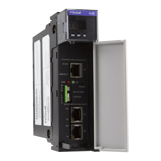
AFC; Ethernet or Serial. The top port (eth0) is used to create Ethernet connections. Serial 1 and Serial 2 are both available for serial connections. You will need the correct cables to connect the MVI56E-AFC to the computer running EAFC Manager. The null-modem cable as well as any required adapter cables are included in the box with the module. - Page 108 This section describes how to connect your PC to one of the serial ports on the module. Connect the DB-9 adapter to a serial port of the MVI56E-AFC (P1 or P2). Refer to the port labels on the front of the module to find the correct port.
- Page 109 MVI56E-AFC ♦ Version 4.04 RSLogix The null-modem cable that is supplied with the module uses the following cabling scheme: Start EAFC Manager, and select the port settings at C OMMUNICATIONS . The default serial communication settings are shown OCAL ETTINGS in the following illustration.
-
Page 111: 17 Downloading The Project To The Mvi56E-Afc
MVI56E-AFC ♦ v4.04 Project Download 17 Downloading the Project to the MVI56E-AFC In EAFC Manager, click P > D ROJECT OWNLOAD ROJECT This action opens the Local Port Settings window. If you are downloading via the network, click TCP/IP: If you are downloading through one of the serial ports, click S ERIAL ProSoft Technology, Inc. - Page 112 RSLogix MVI56E-AFC ♦ Version 4.04 Enter the port parameters to use, and then click D During the download operation, the following progress window is displayed: When the file transfer is complete, the following window is displayed: Troubleshooting Tip: If the EAFC Manager displays an "Illegal Data Value" message, it typically indicates an invalid meter type or product group configuration.
-
Page 113: Creating A Rslogix Project And Importing An Aoi
MVI56E-AFC ♦ Version 4.04 RSLogix 18 Creating a RSLogix Project and Importing an Create an RSLogix Project Create a new RSLogix/Studio 5000 project. In the Controller Organization window, expand the I/O Configuration folder. Select 1756 Backplane, and then click the right mouse button to open a shortcut menu. - Page 114 RSLogix MVI56E-AFC ♦ Version 4.04 On the Select Module dialog box, select 1756-MODULE. Create a new 1756-MODULE (I/O Configuration) with the following settings: Name = MVI56EAFC Comm Format = Data-INT Input Assembly Instance Input Assembly Size = 250 Output Assembly Instance...
- Page 115 Adjust the Slot and RPI settings for your application. 5ms is the recommended default RPI time, do not use an RPI setting below 5ms. Click OK to confirm. The MVI56E-AFC module is now visible in the I/O Configuration folder. ProSoft Technology, Inc. Page 115 of 149...
-
Page 116: Importing The Aoi Rungs
RSLogix MVI56E-AFC ♦ Version 4.04 Importing the AOI Rungs All meter-specific Add-On rungs must precede the Main AOI56EAFC instruction. The meter-specific AOIs can all be on a single rung, but the main AOI instruction must be on a separate rung. See the sample .ACD file for an example of this. - Page 117 MVI56E-AFC ♦ Version 4.04 RSLogix When the following window opens, select the Tags section as shown below: Edit the default AOI rung. The 4 tags are as follows: AFC – This tag must match the tag of the MAIN AOI that you will import last.
- Page 118 MVI56E-AFC ♦ Version 4.04 When finished importing all of the meter type specific rungs that you need for the project, import the MAIN MVI56E-AFC Add-On Instruction. Select the Tags section to display the following menu: The tags shown here are as follows: ...
- Page 119 MVI56E-AFC ♦ Version 4.04 RSLogix When the import is completed, the Add-On Instructions appear similar to the following example: The procedure has imported User-Defined data types that will be used by the sample program. ProSoft Technology, Inc. Page 119 of 149...
- Page 120 RSLogix MVI56E-AFC ♦ Version 4.04 The procedure has imported controller tags that will be used by the sample program. The import procedure is now complete. Save your project and continue configuring the AOI’s section. Note: An example for all 16 meter runs and all 4 meter types is provided as a .ACD file that can be used.
-
Page 121: Configuring The Aois
MVI56E-AFC ♦ Version 4.04 RSLogix Configuring the AOIs Now that all of the AOI’s are in the project you may now configure the ladder for the rest of your application. Below is the sample .ACD file available from the website: ProSoft Technology, Inc. - Page 122 RSLogix MVI56E-AFC ♦ Version 4.04 Page 122 of 149 ProSoft Technology, Inc. October 2, 2018...
-
Page 123: 19 Using The Mvi56E-Afc Web Page
Using the Module Web Page 19 Using the MVI56E-AFC Web Page The MVI56E-AFC web page is accessible through any browser simply by typing the module’s IP address. From this page, you can view general information about the module as well as upgrade the firmware. -
Page 124: Firmware Upgrade Link
Using the Module Web Page MVI56E-AFC ♦ 4.04 The web page opens in your browser. Firmware Upgrade Link Click on the F link in order to upgrade firmware if instructed to IRMWARE PGRADE do so from the support group. Page 124 of 149 ProSoft Technology, Inc. -
Page 125: Component Integrity Link
MVI56E-AFC ♦ 4.04 Using the Module Web Page Component Integrity Link Click on the C link. OMPONENT NTEGRITY The software component integrity table information provides the following information: Software Component – The Software Component column displays the list of legally relevant software identifiers. On the right side of the table, a vertical scroll is provided to scan this listing. -
Page 126: Software Component Detail Information
Using the Module Web Page MVI56E-AFC ♦ 4.04 Software Component Detail Information On mouse hover or click of the legally relevant software component identifier in the table, the software component detail information is displayed below the table. The software component detail information displays the following information. -
Page 127: Component Integrity Page Operation
Using the Module Web Page Component Integrity Page Operation The ProSoft MVI56E-AFC hash checking is performed by an internal process which scans each legally relevant software component once every 4 minutes and 30 seconds. The outcome of this scan is stored in a result file. The hash checking process runs continuously and is independent of all other processes that run on the module. -
Page 128: Verification
“application” firmware-image that adjusts/enhances the “base” environment and components the directly implement the measurement and flow computation. Both firmware images are required for full implementation of the ProSoft MVI56E- AFC Enhanced Liquid & Gas Flow Computer for ControlLogix® module. Both firmware images contain legally relevant software components. - Page 129 MVI56E-AFC ♦ 4.04 Using the Module Web Page Information is viewable for each of the 16 available meters. Click on the appropriate meter for data that pertains to that meter. If you hover or click over a meter, links appear under the appropriate headings.
-
Page 130: Site Configuration
Using the Module Web Page MVI56E-AFC ♦ 4.04 Site Configuration Site Configuration Overview Click on the O link to display the following information: VERVIEW Page 130 of 149 ProSoft Technology, Inc. October 2, 2018... - Page 131 MVI56E-AFC ♦ 4.04 Using the Module Web Page Site status LED indicators are displayed just under the meter selection links. These alarms are displayed on the Site Header, Meter Header, and alarm indication sections Site Header LEDs Site Header Value...
- Page 132 Using the Module Web Page MVI56E-AFC ♦ 4.04 Site Information is located directly below the Site Status LEDs: Parameter Description Project Displays the current project name Serial Number Displays the serial number of the device Firmware version Displays the current firmware version on the module.
-
Page 133: Meter Configuration
MVI56E-AFC ♦ 4.04 Using the Module Web Page Meter Configuration Selecting Meter Streams You can select specific streams per meter from any of the meter pages. Simply select the appropriate meter stream from the drop-down list as shown below: ProSoft Technology, Inc. - Page 134 Using the Module Web Page MVI56E-AFC ♦ 4.04 Meter Configuration Links Meter Configuration contains the following links: Overview Physical Device Identification Process Input Scaling Overview The Meter Configuration page displays the following information: Physical Device The Physical Device page displays the following information:...
-
Page 135: Stream Configuration
MVI56E-AFC ♦ 4.04 Using the Module Web Page Stream Configuration Stream Configuration contains the following links: Overview Identification Analysis Overview Identification Analysis ProSoft Technology, Inc. Page 135 of 149 October 2, 2018... -
Page 136: Meter Calculations
Using the Module Web Page MVI56E-AFC ♦ 4.04 Meter Calculations Meter Calculations provide the following data: Reference Conditions Process Inputs Heating value Flow Calculations Flow Rates Reference Conditions Process Inputs Page 136 of 149 ProSoft Technology, Inc. - Page 137 MVI56E-AFC ♦ 4.04 Using the Module Web Page Heating Value Flow Calculations Flow Rates ProSoft Technology, Inc. Page 137 of 149 October 2, 2018...
-
Page 138: Meter Accumulators
Using the Module Web Page MVI56E-AFC ♦ 4.04 Meter Accumulators Meter Accumulators provide the following data: Quantity Rollover Resettable Non-Resettable Quantity Rollover Resettable Non-Resettable Page 138 of 149 ProSoft Technology, Inc. October 2, 2018... -
Page 139: Meter Status
MVI56E-AFC ♦ 4.04 Using the Module Web Page Meter Status The meter status area provides alarm information for the selected meter and stream. In this example, the Active Stream indicates the active stream for Meter 1. You can change the meter stream by selecting the requested stream from the Meter Stream dropdown. - Page 140 Using the Module Web Page MVI56E-AFC ♦ 4.04 Meter enable Displays meter enable/disable state. Checksum Alarms Click to display details on the following: Alarm Indicators – Checksum Alarms Meter alarm Alarm Indicators – Meter Alarms Alarm Indicators – Meter Errors Process Input ...
-
Page 141: Data Displays
MVI56E-AFC ♦ 4.04 Using the Module Web Page Data Displays In addition to the information provided above, the web page displays current data along the bottom of the page. This information displayed automatically changes every few seconds and displays: ... -
Page 143: 20 What's Next
Congratulations! Your MVI56E-AFC is now configured and running. There are a number of features and customizations that you can set up and use. The MVI56E-AFC Reference Guide contains a wealth of information that will help you get the most out of your module. - Page 144 What’s Next MVI56E-AFC ♦ 4.04 In addition, the MVI56E-AFC Reference Guide provides further information on: Modbus communication Modbus database information Modbus communication parameters Modbus transaction sequencing and constraints Product groups Calculation results Molar Analysis ...
-
Page 145: 21 Support, Service And Warranty
Details about the serial, Ethernet or Fieldbus devices interfaced to the module, if any. Note: For technical support calls within the United States, ProSoft’s 24/7 after- hours phone support is available for urgent plant-down issues. Detailed contact information for all our worldwide locations is available on the following page. - Page 146 Support, Service and Warranty MVI56E-AFC ♦ Version 4.04 Setup and Configuration Guide Europe / Middle East / Africa Asia Pacific Regional Office Regional Office Phone: +33.(0)5.34.36.87.20 Phone: +603.7724.2080 europe@prosoft-technology.com asiapc@prosoft-technology.com Languages spoken: French, English Languages spoken: Bahasa, Chinese, English, REGIONAL TECH SUPPORT Japanese, Korean support.emea@prosoft-technology.com...
-
Page 147: Warranty Information
Phone: +54.911.4565.8119 scone@prosoft-technology.com Languages spoken: Spanish, English Warranty Information For complete details regarding ProSoft Technology's TERMS & CONDITIONS OF SALE, WARRANTY, SUPPORT, SERVICE, and RETURN MATERIAL AUTHORIZATION INSTRUCTIONS, please see the documents at: www.prosoft-technology/legal Documentation is subject to change without notice. -
Page 149: 22 Index
MVI56E-AFC ♦ Version 4.04 Support, Service and Warranty Setup and Configuration Guide Pinouts • 2, 3 22 Index Poll Button • 44 Port Options • 42 Accessing the Data • 46 Read Button • 45 Accumulator Totalizer and Residue • 75 Remapping Button •...
Need help?
Do you have a question about the MVI56E-AFC and is the answer not in the manual?
Questions and answers