Table of Contents
Advertisement
Advertisement
Table of Contents

Summary of Contents for Accufast P4
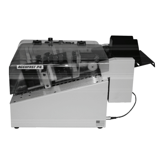
- Page 1 ACCUFAST P4 Small Envelope and Card Printer User’s Guide and Operating Manual...
-
Page 2: Table Of Contents
Table of Contents 1.0 Introduction 1.1 Items Included 1.2 Operating Manual Safety Terms 1.3 Safety Precautions 1.4 Power Connection and Fusing 2.0 Specifications and Requirements 2.1 Specifications 2.2 Requirements 3.0 Unpack and Setup 4.0 Mechanical Operation 4.1 Loading and Feeding Pieces 4.2 Feeder Set Up 4.3 Lining up the Print on the Piece 4.4 Controls, Adjustments and Indicators... -
Page 3: Introduction
The ACCUFAST P4 Small Envelope and Tag Printer is a simple, pro- ductive specialty printer designed to offer it’s owner years of trouble free operation. The P4 is equipped to print on a wide variety of media sizes and types. A variety of feeding units are used to match the diver- sity of media that the P4 prints. -
Page 4: Operating Manual Safety Terms
1.2 Operating Manual Safety Terms The following Blocks are used to draw the operator’s attention to impor- tant information. These blocks are set up in order of importance based on operator safety. WARNING USED TO ALERT THE OPERATOR TO CONDITIONS OR ACTIONS WHICH MAY PRESENT HAZARDS OR CAUSE PERSONAL INJURY Caution... -
Page 5: Power Connection And Fusing
1.4 Power Connection and Fusing The P4 is fused in both legs of the main power entry line. Accordingly, it can accept power from most services at all common voltages and amper- ages. The correct voltage is set at the factory. -
Page 6: Specifications And Requirements
2. Specifications and Requirements 2.1 Specifications Size and Weight: P4: 16.0” long x 12” high x 16.5” wide With card feeder: 22” long x 16” high x16” wide With Wide Feeder: 26” long x 20” high x 23” wide P4: 35 Lb. -
Page 7: Unpack And Setup
Note Report any signs of shipping damage to the carrier immediately. Open the Printer carton and remove the printer and accessory box. Belt Tracking The input end of the P4 is Adjustment pictured at right. Remove Screw the Encoder Shipping Knob first. - Page 8 ACCUFAST P4 Paper Guide Ink Jet Printer Extensions Tag Feeder Feeder mounting Slots (4) Feeder power connection Feeder Mounting Hooks (4) Feeder power cable To mount the Small Envelope and Tag Feeder: 1. Open the Printer Top Cover 2. Lift the Tag feeder up so that the Paper Guide Extensions are over the printer transport tray.
- Page 9 The Wide Format Feeder (ACCUFAST FX) merely sits on a stand at the input end of the P4. To set it up: 1. Unpack the Feeder and the Stand 2. Place the Stand against the Printer’s input end 3. Set the Feeder on the stand and slide it up to the printer.
-
Page 10: Mechanical Operation
4. Mechanical Operation 4.1 Loading and Feeding Pieces Both ACCUFAST Feeders covered in this publication work the same way. They have an adjustable separator and paper guides that control the thickness and location of the pieces being fed. They take power from the printer and run at variable speed controlled from the printer’s speed... -
Page 11: Feeder Set Up
4.2 Set Up the Feeder 1. Turn the printer transport OFF—Lift Printer Cover 2. Loosen the Feeder Piece Separator 3. Loosen the media side guides in the feeder. 4. Mark the first piece to be fed with the general area of desired print lo- cation. -
Page 12: Lining Up The Print On The Piece
Input Roll lock knob Imager height Input adjust- Roll ment Scale Envelope to be printed Vacuum Belt Pens 1 and 2 Print Location Empty stalls mark for pens 1&2 4.3 Lining Up the Print on the Piece 1. Once the Feed and Transport components have been set and locked in place, slide the first, marked piece under the separator ( this might require loosening the separator again,) 2. -
Page 13: Controls, Adjustments And Indicators
4.4 Controls, Adjustments and Indicators Transport Belts Main Power and Feeder Feed Speed Indicator Feed only Switch Imager Height Adj. Knob Product side guide latch Separator Lock Knob Input Roll Lock Knob 1. Main Power Switch: Black single pole switch on rear of machine shown on page 9. -
Page 14: Loading Ink
4.5 Loading Ink Open Latch Pen catch Pen Stall Latch caught on pen exposed Imager 2 Pens 3&4 Warning decal Ink Cartridge ( Pen) To insert a cartridge (pen) without moving the imager on its slide follow this procedure. Use only the type and brand of ink specified with your printer. -
Page 15: Feeding Pieces
4.6 Feeding Pieces Once the Feeder and Printer have been set up and pieces loaded in the feeder, it is time to begin to test and refine the set ups to obtain the best print quality possible. The feeder should have a small stack of material in the hopper, ready to feed, and the power to the machines should be OFF. -
Page 16: Feed Adjustments
4.7 Feed Adjustments It is common to make adjustments to the feed and transport of pieces prior to printing. It is useful to do so. Skew: First, Identify where the Skew enters the piece by watching it move through the machine. If an imager is too low, it will drag a piece and cause a jam or skew. -
Page 17: Software And Printing
5.0 Software and Printing The software that controls the ACCUFAST P4 comes in two sections, a print driver and a printer controller. The driver interprets output from any program and sends it to the printer controller. The printer controller is on screen, the windows driver is in the background. -
Page 18: Piece Design And Layout
2. Set both the top and left margins to 0 3. Enter the text, graphics, bar codes etc. that you wish to print. 4. Start the ACCUFAST Stitch line application 5. Place the stitch line overlay in the top left corner of the text. -
Page 19: Print A Document
5.4 Printing a Document When you print to the ACCUFAST P4, you format and send the items on the screen to the printer. This may take bit of time, depending on the complexity of the file being printed. A traffic light icon will appear along the bottom of the windows screen as one of the minimized program icons. -
Page 20: Printer Controls
5.5 Printer Controls Start with the “Start Print Job” (Green) button in the upper left corner of the control panel screen. The box just under the start/stop button con- tains 2 check boxes. Show pages while printing when checked the control panel scrolls through the pages of a variable data list. - Page 21 To the right of the set up box is the ink status box. The ACCUFAST P4 holds four HP45A style cartridges arranged electrically into one imager. This master imager is then split into two sections usually called imagers as well. The Control panel monitors the usage of ink in each cartridge.
-
Page 22: Advanced Set Up
The IMAGER Setup box contains Imager details and adjustments that effect communication and printer performance. The ACCUFAST P4 only has one imager, The Control Panel can be set up to handle up to 4 imagers, but leave it set at 1 as there is no other. - Page 23 There are 4 basic categories of ink. ACCUFAST uses print applications as a guide, assuming that for specialty printing, specialty inks have been purchased. For plain paper printing, use the Versatile or Overcoat set- tings. (Overcoat is the factory default.) For IR drying, use General. For UV Cure applications, select UV Ink.
-
Page 24: Stop Printing
Lifting the Cover or Pressing the Transport Switch will stop all moving parts and act as an Emergency Stop in case of a problem or jam. When re-starting, always turn the feed Speed down and the Feeder off before starting the P4 transport. -
Page 25: Maintenance
6.0 Maintenance The single most important maintenance factor is correct operation. Make sure that all correct procedures are followed. If so, maintenance will be routine and limited to cleaning and simple adjustments. 6.1 Ink and Pen Cleaning When the ink level indicator drops to about 10%, pay close attention to the print quality from that pen. -
Page 26: Pen Capping And Storage
6.2 Pen Capping and Storage Notch on Pen Pen Cap Ink cartridge (Pen) Capped Pen for Storage. 1. Remove and clean the pen. 2. Rock the Pen into its capping clip locking the clip over the notch. 3. Store at room temperature. 4. -
Page 27: Cleaning
Belt tracking Screws 6.4 Cleaning Keep the machine clean. Use a damp cloth (not the lint free pen clean- ing cloth) to wipe down all exterior surfaces. After prolonged usage, the belts may have ink build up on them. With the cover up and the machine unplugged, rotate the belts and wipe down each new area with a wet cloth until excess ink has been removed. -
Page 28: Trouble Shooting
7.0 Trouble Shooting Problem Cause Solution Belts Don’t turn, Cover not down Press the Cover fully Power indicator down to engage the On, Switches ON safety switch. Cover will not close with a pen lever No print. Belts No belt speed in Status Encoder failure.
Need help?
Do you have a question about the P4 and is the answer not in the manual?
Questions and answers