
Summary of Contents for Hanasis HW-3000
- Page 1 HW-3000 ※ Please read and learn the manual carefully for your safety and proper way of use. e-Manual...
-
Page 2: System Installation No
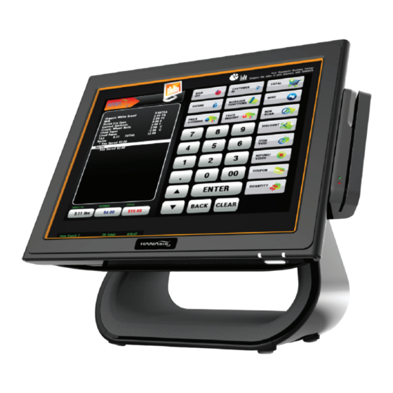
System Introduction Touch Screen System Block Diagram Remove the protective tape Safety precautions MotherBoard Layout Adjusting Viewing Angle HW-3000 preview Kitchen Printer Setting Jumper Connecting DC Power Specification & options Supply Cable & System on Winclon (Backup) I/O Pin Assignment Locations ㆍCOM 1, COM 2/ 3... - Page 3 For your security and to prevent damage, please read the following safety instructions carefully. Failing to follow instructions marked with this symbol may cause personal injury and even fatality. HW-3000 preview Specification & options Do not block the ports(holes), Vents, etc, of the system and do not insert objects.
-
Page 4: Assembly & Disassembly
BIOS The symbol mark is the foundation element that symbolizes the Hanasis corporation and it is also a symbol of communication at both home and abroad. The basic concept is a leading IT industry. It embodies Hanasis's corporate goal to link world faster by using advanced IT technology. - Page 5 Contents Specification & options System Introduction Safety precautions ◆ Specification ◆ Options HW-3000 preview Microsoft ® Windows7, POSReady7 / 2009, windows XP Processor(CPU) Intel ® 1037U Dual-Core (1.8GHz, 2M Cash) Celeron ® Specification & options Wall Mount Fixed Type , Swivel Type...
- Page 6 Contents Parts description System Introduction Cover cable Safety precautions HW-3000 preview Dual(touch) monitor Specification & options (9.7” / 15”) Card reader (MSR) Locations Power supply lamp ㆍParts description Error lamp Reset button ㆍI/O port Barcode scanner(Option) Camera(Option) HDD lamp ㆍRating label zone LAN lamp Power button &...
- Page 7 Contents I/O port System Introduction Safety precautions HW-3000 preview (standard) Specification & options MOUSE LINE-OUT Locations COM2 COM3 HDD Tray ㆍParts description POWER ㆍI/O port MIC-IN COM4 (USB) COM1 (12V) (12V) ㆍRating label zone System Installation PS/2 (MOUSE) PS/2 type of mouse...
-
Page 8: Bios
Contents Rating label zone System Introduction Safety precautions HW-3000 preview Specification & options Locations ㆍParts description ㆍI/O port ㆍRating label zone System Installation Using the product Assembly & Disassembly BIOS Appendix... -
Page 9: Appendix
Contents Remove the Protective Tape System Introduction Before you setup the product(HW-3000). Remove the protective tape before setup. System Installation Remove the protective tape Adjusting Viewing Angle Connecting DC Power Supply Cable & System on Using the product Assembly &... - Page 10 Contents Adjusting Viewing Angle System Introduction For optimal viewing it is recommended to look at the full face of the monitor, then adjust the monitor's angle to your own preference. You are able to adjust the monitor's angle from 5°to 50°. System Installation Remove the protective tape Adjusting Viewing Angle...
- Page 11 Contents Connecting DC Power Supply Cable & System on System Introduction Connect the power cord to the AC adaptor firmly. Use only the AC adaptor supplied with the product. Otherwise, there is a danger of fire due to an incomplete contact. Do not touch the system plug or power cord with wet hands System Installation Remove the protective tape Please always check the directions.
- Page 12 Contents Touch Screen ■ Touch Point Setup System Introduction When you use the touch screen for the first time or the pointer does not precisely match your touch, calibrate the touch screen System Installation in the ‘eGalaxTouch’. The calibration process for the touch screen may differ depending on the operating system and may not be available in some operating systems.
- Page 13 Contents ■ Proper way of using the card reader System Introduction Learn the proper way of using card reader before using the product. System Installation When the card is inappropriately recognized, the red ligth will be turned on with the beep sound. Using the product Touch Screen Kitchen Printer...
- Page 14 ■ cable connection specification for kitchen printer serial cable System Introduction In order to connect POS device with kitchen printer, please regard to the following connection drawing. System Installation You must use the interchangable gender that is provided by Hanasis. Using the product Touch Screen Extension Cable...
- Page 15 Contents Winclon (Backup) ■ HDD Backup System Introduction (The programs may vary depending on different model.) Back up your current Window user environment into restore field. System Installation It is much easier to operate if you know where the data is being backed up. You need to connect key board before you turn the power on.
- Page 16 Contents Winclon (Restore) ■ HDD Backup System Introduction (The programs may vary depending on different model.) You can recover quickly despite when you are not able to boot from the OS or when having any problems. System Installation Keyboard and mouse must be connected. If you recover the Hard disk, all the data of the system will be deleted.
- Page 17 Contents POS Driver and Utility System Introduction All the drivers and data that are provided with your purchase are in the D drive of Hard disk. System Installation Using the product Touch Screen Drivers Kitchen Printer Utility Winclon (Backup) Manual Winclon (Restore) POS Driver &...
- Page 18 Contents ■ MSR separation System Introduction When reassembling the card reader, you must assemble tightly otherwise the card will not be recognized by the reader. System Installation Using the product Screw Assembly & Disassembly Stand HDD Tray Rear Cover (USB) Cover cable 9.7”...
- Page 19 Contents Stand ■ Stand separation System Introduction The stand is heavy so please be careful with it. When reassembling, for your safety, System Installation you must put the lever in the correct insertion point. Using the product Lever Assembly & Disassembly Stand Rear Cover...
- Page 20 Contents ■ Hard Disk Drive Replacement System Introduction Care must be taken when removing the HDD and bracket to avoid injury. System Installation Save all your data before clicking on Shut down. Disconnect the Adaptor cable from the system. Using the product Assembly &...
- Page 21 Contents Rear Cover ■ Rear Cover separation System Introduction 1) before you lay down the product, please remove anything that could damage the product and touch panel, System Installation and then spread a clean fabric or cloth before you start the operation. 2) The disassembling and assembling process require professionality.
- Page 22 Contents ■ EMI separation System Introduction System Installation Check the caution for disassembling before disassemble EMI. Using the product Dual monitor Assembly & Stand Disassembly Stand Screw Rear Cover Cover cable Rear cover 9.7” Dual monitor Card reader (MSR) 15” Dual monitor Wall mount ①...
- Page 23 Contents 9.7” Dual monitor & Dual touch monitor - Step 1 ■ Setup & Connecting DC power supply cable System Introduction Connect the power cord to the AC adaptor firmly. Use only the AC adaptor supplied with the product. System Installation Otherwise, there is a danger of fire due to an incomplete contact.
- Page 24 Contents 9.7” Dual monitor & Dual touch monitor - Step 2 ● Dual(Dual touch) monitor Setting System Introduction The setting method may vary regarding to OS and version of graphic drivers. System Installation Please refer to relevant website for the latest driver and detailed setting method. [ POSReady 7, Windows 7 ] [ POSReady2009, Windows XP ] Using the product...
- Page 25 Contents 15” Dual monitor & Dual touch monitor - Step 1 ■ Setup & Connecting DC power supply cable System Introduction Save all your data before clicking on Shut down. Disconnect all cables and the Adaptor cable from the system. System Installation Connect 15”monitor adapter to dual power cable.
- Page 26 Contents 15” Dual monitor & Dual touch monitor - Step 2 ● Dual(Dual touch) monitor Setting System Introduction The setting method may vary regarding to OS and version of graphic drivers. System Installation Please refer to relevant website for the latest driver and detailed setting method. Using the product [ POSReady 7, Windows 7 ] [ POSReady2009, Windows XP ]...
- Page 27 Contents Wall Mount ■ Wall Mount installation System Introduction 1) Connect the power cord to the AC adaptor firmly. Use only the AC adaptor supplied with the product. System Installation 2) You may be injured by using various tools so please ask experts for help when installing. Using the product Progress after disassembling the stand.
- Page 28 Contents NFC - Step 1 ■ Setup & Connecting DC power supply cable System Introduction Connect the power cord to the AC adaptor firmly. Use only the AC adaptor supplied with the product. System Installation Otherwise, there is a danger of fire due to an incomplete contact. Do not touch the system plug or power cord with wet hands. Using the product Cover cable Assembly &...
- Page 29 Contents NFC - Step 2 ● BIOS Setup (NFC Voltage) System Introduction You need to connect key board before you turn the power on. System Installation Please refer to our website for the detailed information about BIOS set up. Connect the power cord to the AC adaptor firmly. Use only the AC adaptor supplied with the product. Using the product Otherwise, there is a danger of fire due to an incomplete contact.
- Page 30 Contents NFC - Step 3 Aptio Setup Utility - Copyright (C) 2011 American Main Advanced Topstar Chipset Boot Security Save & Reset System Introduction IT8786 Super IO Configuration IT8786 Super IO Chip IT8786 ▶ Serial Port 1 Configuration ▶ Serial Port 2 Configuration System Installation ▶...
- Page 31 Contents BARCODE SCANNER - Step 1 ■ Setup & Connecting DC power supply cable System Introduction Connect the power cord to the AC adaptor firmly. Use only the AC adaptor supplied with the product. System Installation Otherwise, there is a danger of fire due to an incomplete contact. Do not touch the system plug or power cord with wet hands. Using the product Cover cable Assembly &...
- Page 32 Contents BARCODE SCANNER - Step 2 ● BARCODE SCANNER Reset Default GuideaA System Introduction Please read the direction carefully and safely set up the product accordingly. System Installation Please follow the procedure below. 1) Please avoid setting when the store is crowded. Please set-up forehand before the store opens or after the store is closed. Using the product When start to set-up, stop and save all of your work.
- Page 33 Contents BIOS Setup System Introduction You need to connect key board before you turn the power on. Please refer to our website for the detailed information about BIOS set up. System Installation The BIOS setup enables you to configure your system hardware according to your needs. Use the BIOS setup to define a boot password, change the booting priority, or add a new device.
-
Page 34: System Block Diagram
Contents System Block Diagram System Introduction System Installation Using the product Assembly & Disassembly BIOS Appendix System Block Diagram MotherBoard Layout Setting Jumper I/O Pin Assignment... -
Page 35: Motherboard Layout
Contents MotherBoard Layout LVDS Panel Connector Inverter Power Header System Introduction System Introduction Panel Power Jumper ATX 12V Power Connector CPU Fan Connector Chassis Fan Connector System Installation System Installation SoDIMM Memory Slot (DDR3) SATA Power Connector SATA3 Connector Using the product Clear CMOS Header SATA2 Connector mini PCI Express Slot(mSATA Slot) -
Page 36: Setting Jumper
Contents Setting Jumper System Introduction ■ Jumper Setup Jumper cap System Installation The illustration shows how jumpers are setup. When the jumper cap is placed on pins,the jumper is “Short”. Using the product If no jumper cap is placed on pins, the jumper is “Open”. Jumper pin The illustration shows a 3-pin jumper whose pin1 and pin2 are “Short”... - Page 37 Contents IO Pin Assignment System Introduction ■ COM 1 - Serial Port (DSUB 9 Pin) Signal Description System Installation RS-232 RS-422 RS-485 Using the product RX (-) TX (+) Data (+) Assembly & Disassembly BIOS TX (-) Data (-) RX (+) Appendix System Block Diagram ■...
-
Page 38: Table Of Contents
Contents IO Pin Assignment System Introduction ■ COM 4 Port (RJ-45) Signal Description System Installation Using the product Assembly & Disassembly BIOS 8 8 8 Appendix System Block Diagram ■ VGA Port (DSUB 15 Pin) MotherBoard Layout Signal Description Signal Description Setting Jumper Analog - RED Analog - GRN... - Page 39 Contents IO Pin Assignment System Introduction ■ LAN Port (RJ-45 with LED) Signal Description System Installation MD0 (+) MD0 (-) Using the product MD1 (+) MD1 (-) Assembly & MD2 (+) Disassembly MD2 (-) BIOS MD3 (+) MD3 (-) 8 8 8 8 Appendix System Block Diagram ■...
- Page 40 Contents IO Pin Assignment System Introduction ■ USB Port (TYPE-A) System Installation Signal Description VUSB (5.0V) USB D(-) Using the product USB D(+) Assembly & Disassembly BIOS ■ DC-IN (Power DIN-4) Appendix Signal Description +12V System Block Diagram Mother Board Layout +12V Setting Jumper I/O Pin Assignment...
- Page 41 Contents IO Pin Assignment System Introduction ■ PS/2 MOUSE (DIN 6 Pin) Signal Description System Installation DATA DATA Using the product VCC +5V VCC +5V Assembly & CLOCK CLOCK Disassembly BIOS Appendix System Block Diagram ■ PS/2 KBD (DIN 6 Pin) Mother Board Layout Signal Description Setting Jumper...
- Page 42 □ Head Office □ R&D Center ・ A/S Center #517 Anyang Mega Valley, 268, Hagui-ro, B-1927 Geumgang Penterium IT Tower, 282, Hagui-ro, Dongan-gu, Anyang-si, Gyeonggi-do 431-767, Korea Dongan-gu, Anyang-si, Gyeonggi-do 431-810, Korea +82-31-337-5770 +82-31-337-5771 +82-31-426-4343 +82-31-426-4381...
Need help?
Do you have a question about the HW-3000 and is the answer not in the manual?
Questions and answers