
Summary of Contents for L3 Aviation Products SDU L-3
- Page 1 Iridium Iridium ® ® Welcome Welcome Package Package Package Package Airbus Iridium SATCOM System...
-
Page 2: Cattlemen Road, Sarasota, Florida
100 Cattlemen Road, Sarasota, Florida 34232 Telephone: 941-371-0811 Facsimile: 941-377-5591 Welcome! Dear Valued Customer, All of us at L-3 Aviation Recorders take this opportunity to say “thank you” for your selection of the L-3 Airbus Iridium Satellite Communication (SATCOM) system. This SATCOM system, also identified as the Automated Flight Information &... - Page 3 100 Cattlemen Road, Sarasota, Florida 34232 Telephone: 941-371-0811 Facsimile: 941-377-5591 Electronic Flight Bag (EFB) Interface If desired, the Iridium SATCOM System SDU provides an EFB with an interface to the EFB message transport system. An Ethernet port provides the physical connection between the devices – using industry standard IEEE 802.3 LAN technologies.
- Page 4 100 Cattlemen Road, Sarasota, Florida 34232 Telephone: 941-371-0811 Facsimile: 941-377-5591 Table of Contents This Welcome Package includes the documents listed in the table below. Keep in mind, these documents may not be the latest up-to-date revisions. Please check the L-3 Customer Support website for the latest update available at: http://www.l-3ar.com/customer/index.htm Documents...
- Page 5 Sarasota, Florida 34232 Fl id 34232 CAGE Code 06141 Phone: (941) 371–0811 | FAX: (941) 377–5591 http://www.l-3ar.com/ Iridium Customer Support Iridium Customer Support Technical support, Reliability, Product support Daren Welker Carlo Mammelli Dave Dowding Product Support Engineer Publications Supervisor Senior Product Support Engineer Phone 941.379.1620 Phone 941.377.5550 Phone 941.377.5551 Cell Cell 941.372.2313 941 372 2313 Cell Cell 941.726.9050 941 726 9050 Cell Cell 941.284.3048...
- Page 6 Sarasota, Florida 34232 CAGE Code 06141 Phone: (941) 371–0811 | FAX: (941) 377–5591 http://www.l-3ar.com/ Authorized Service Facility Authorized Service Facility A European service facility will be established later in 2014. Until such time, all Iridium repairs will be performed at L‐3 Factory. Address: L‐3 Communications Aviation Recorders 100 Cattlemen Rd. Sarasota, Florida 34232 Attention: Repair Station 941 377 5517 Attention: Repair Station – 941‐377‐5517 Repair Station Manager: Gerald Godbee Phone: 941.377.5531Email: gerald.godbee@l‐3com.com...
- Page 7 Airbus Iridium SATCOM System Airbus Iridium SATCOM System Quick Start Guide SDU L-3 part number 228E5733-00 SCM L-3 part number 418E5733-00 L‐3 Aviation Recorders Proprietary 165E5733‐01 Rev. 02 7 March 2014 Page 1 ...
- Page 8 Airbus Iridium SATCOM System SECTION 1 ‐ OVERVIEW 1. Airbus Iridium SATCOM System Overview The Airbus Iridium SATCOM System will be certified to TSO C‐159a for voice and data safety‐services. It has a dual‐channel Iridium link, one dedicated for data ‐ with the capability to send and receive standard ACARS messages between the aircraft’s Air Traffic Service Unit (ATSU), and the other prioritized for voice via a certified terrestrial service provider. The Automated Flight Information Reporting System (AFIRS) provides a satellite voice and data ® communications (SATCOM) link with the Public Switched Telephone Network (PSTN) via the Iridium satellite network. The system uses a standard ARINC 741/761 SATCOM interface to the flight crew’s Audio Integrating System and ARINC 739A Multi‐Purpose Control and Display Units (MCDUs) in the cockpit, as well as providing 3‐extension Public Branch Exchange (PBX) capability for up to 2 handsets in the cabin. L‐3 Aviation Recorders Proprietary 165E5733‐01 Rev. 02 7 March 2014 Page 2 ...
- Page 9 Airbus Iridium SATCOM System Satellite Data Unit (SDU) 2. SDU Configuration Module (SCM) The SCM is housed in a small enclosure, which is designed to be mounted within 24” of the SDU rear connector. The SCM and antenna connect directly to the SDU. The SDU is the heart of the system and provides all of the interfaces to other aircraft systems. L‐3 Aviation Recorders Proprietary 165E5733‐01 Rev. 02 7 March 2014 Page 3 ...
- Page 10 Airbus Iridium SATCOM System SECTION 2 – SYSTEM CONFIGURATION You configure the Airbus Iridium SATCOM System Satellite Data Unit (SDU) via Ethernet using a laptop, web browser, and the AFIRS Maintenance User Interface (MUI). An RJ‐45 Maintenance Port jack is located behind the access door on the front panel of the SDU. IMPORTANT: READ BEFORE CONFIGURING SATCOM SYSTEM The MUI only accepts English‐language characters and numbers. The aircraft’s status must be deemed “On‐Ground” to access Maintenance Mode and make any system changes. If the aircraft is deemed “In‐Air”, the Enter Maintenance Mode button will be, or will become, unavailable. If the aircraft status changes to “In‐Air” while in Maintenance Mode, the system will reboot automatically and return to Operational Mode without saving any changes. Entering Maintenance Mode disables all MCDU functions. L‐3 Aviation Recorders Proprietary 165E5733‐01 Rev. 02 7 March 2014 Page 4 ...
- Page 11 Airbus Iridium SATCOM System 1. Install SIM Card 1. Remove the four screws from the plate on the SCM. 2. Remove the plate on the SCM to reveal the SIM enclosure. 3. Slide the SIM Enclosure to release. 4. Lift the SIM Enclosure. L‐3 Aviation Recorders Proprietary 165E5733‐01 Rev. 02 7 March 2014 Page 5 ...
- Page 12 Airbus Iridium SATCOM System 5. Slide the SIM card in the slot. It will fit only one way; do not force. 6. Close the SIM Enclosure and slide to the left to lock. The SIM Card is now installed. 7. Replace the plate. 8. Replace the four screws using a small amount of threading Loctite 222. 9. Proceed to “Access the Maintenance User Interface (MUI)” below. L‐3 Aviation Recorders Proprietary 165E5733‐01 Rev. 02 7 March 2014 Page 6 ...
- Page 13 Airbus Iridium SATCOM System 3. Access the Maintenance User Interface (MUI) 1. With system power on, connect an Ethernet cable to the Maintenance Port via the front panel access door of the SDU. 2. Connect the other end of the cable to a laptop with a web browser (Mozilla FireFox® is recommended). 3. Confirm that the green link light is illuminated. The light can be steady or flashing – flashing means that data is being transmitted. 4. Set the laptop network adapter to the following: IP = 192.168.128.10 Subnet Mask =255.255.255.0 Note: The Maintenance port can auto‐negotiate the best speed (10/100) and mode (full/half duplex). 5. Open the laptop’s web browser and clear the cache. 6. In the Address bar, type the following default IP address: 192.168.128.1. The Airbus Iridium SATCOM System Home page will display with the General tab information displayed. L‐3 Aviation Recorders Proprietary 165E5733‐01 Rev. 02 7 March 2014 Page 7 ...
- Page 14 Airbus Iridium SATCOM System 1 ‐ Login area 2 ‐ Menu of available links to pages accessible to various users upon login 3 ‐ Tabs: GENERAL, ARINC, and DISCRETE IN 4 ‐ System and Link status display area 5 ‐ System information data display area 6 ‐ Mode: OPERATIONAL, MAINTENANCE, INITIALIZING, etc. 7. Proceed to “Access Maintenance Mode” below. 4. Access Maintenance Mode – On Ground Status Required 1. You are now connected to the Airbus Iridium SATCOM System MUI Home Page; type the following in the Login fields: Default User Name: AFIRSMAINT Default Password: 228MAINT 2. Click Login. 3. Click Enter Maintenance Mode. A message displays, prompting for confirmation to enter Maintenance Mode. 4. Click OK. The MUI – Maintenance Home Page will display. 5. Modify Owner Requirements Table (ORT) Parameters 1. You are logged into the MUI as a Maintenance User from the previous process. You will now be able to customize parameters for the individual aircraft operator based on operational requirements or preferences. 2. Click Enter Maintenance Mode. A confirmation message displays. 3. Click OK. L‐3 Aviation Recorders Proprietary 165E5733‐01 Rev. 02 7 March 2014 ...
- Page 15 Airbus Iridium SATCOM System 4. Click the ORT link on the left side of the screen to open the ORT page. The Owner Requirements Table will display. Field Available Options Call Progress Tones North American European Extension 1 Yes – Calls from cockpit can be placed manually No – Calls from cockpit can only be placed from address book Low Priority Calls Yes – Low priority calls can be received/made from cockpit No – Low priority calls cannot be received/made from cockpit Additional ACARS None – SITA Service Header ARINC – ARINC Service Air Traffic Service (ATS) Yes – SIM card with ATS No – SIM card without ATS 6. Create an Address Book 1. Click Downloads from the left menu. 2. Choose the Address Book option. 3. Click Download. 4. Choose the Save File option. L‐3 Aviation Recorders Proprietary 165E5733‐01 Rev. 02 7 March 2014 ...
- Page 16 Airbus Iridium SATCOM System 5. Click OK. An Address Book template will download to the computer as a comma‐separated‐values file (adb.csv). If the computer does not have Microsoft Excel®, the file can be opened as a Microsoft WordPad® file. Example of Microsoft Excel® Address Book file. Example of Microsoft WordPad® Address Book file. 6. Locate and open the adb.csv file. 7. Add entries to the address book (up to 300) and modify as necessary. There are no list numbers in the adb.csv file to identify individual entries. Important: The template (adb.csv) entries must adhere to the parameters exactly. Address Book Parameters Phone Number Up to 18 digits (Always include country code) Name Up to 23 upper‐case alpha‐numeric characters (A‐Z, 0‐9, +, ‐, /, space) Priority 4 – Public Use only ATS‐ 3 – Non‐Safety enabled Iridium 2 – Safety SIM cards. 1 – Emergency Protected 0 – No 1 – Yes Directory 4 – Public 3 – Non‐Safety 2 – Safety 1 – Emergency Speed Dial 1 1 ...
- Page 17 Airbus Iridium SATCOM System 10. Click Browse and locate the adb.csv file that you just created. 11. Click Upload. 12. Click Apply. 13. Click Exit Maintenance Mode when updates are complete. A message displays, prompting for confirmation to exit Maintenance Mode. 14. Click OK. The system saves changes, reboots, and returns to Operational Mode. 15. Proceed to “Enter Administrator Role” below. 7. Enter Administrator Role ‐ On‐Ground Status Required 1. You are still connected to the Airbus Iridium SATCOM System MUI Home Page; type the following in the Login fields: Default User Name: AFIRSADMIN Default Password: ADMIN228 2. Click Login. 3. Click Enter Maintenance Mode. L‐3 Aviation Recorders Proprietary 165E5733‐01 Rev. 02 7 March 2014 Page 11 ...
- Page 18 Airbus Iridium SATCOM System 8. Update User Access Table (UAT) Parameters The User Access Table (UAT) is used to set up user access privileges for up to 20 users. These settings may be changed as needed to meet operational requirements. 1. Click the UAT (Security) link on the left side of the screen to open the UAT page. 2. Add security roles as necessary based on the following parameters. Field Parameter User Name 4 ‐ 20 upper‐case alpha‐numeric characters Password 4 ‐ 20 upper‐case alpha‐numeric characters Security Level Data Collector (default) Maintenance Administrator Privileges Modifications Software/Data Loading (Upload) (User ADB (User ORT Address Access S/W ORT (Address Access Roles Parameters Book Table) Upgrades ...
- Page 19 Airbus Iridium SATCOM System a. Download Backup UAT File (Optional) You may want to download a backup UAT file that you could upload in the event that the system file should fail. 1. On the Home Page, type the following in the Login fields: Default User Name: AFIRSADMIN Default Password: ADMIN228 2. Click Login. 3. Click Downloads. 4. Select the UAT option from the Configurations section. 5. Click Download. 6. Choose Save. 7. Click OK. 8. Proceed to “Section 3 ‐ Testing” below. L‐3 Aviation Recorders Proprietary 165E5733‐01 Rev. 02 7 March 2014 Page 13 ...
- Page 20 Airbus Iridium SATCOM System SECTION 3 – TESTING 1. Test System Voice Connectivity Perform the following steps to ensure that the system is working properly. If you do not have voice transmission available, proceed to Test System Data Connectivity. For information on Built‐in Tests and Fault Indicators, see the Installation and Operations Manual. a. Call from Landline Phone to Iridium SATCOM Phone NON‐ATS (Air Traffic Service) SIM 1. Call Iridium Call Service U.S. 1‐480‐768‐2500 Non‐U.S. 001‐480‐768‐2500 2. Enter Iridium 12 digit phone number and follow with the # symbol. ATS (Air Traffic Service) SIM 1. Call Iridium Call Service U.S. 1‐480‐730‐3900 Non‐U.S. 001‐480‐730‐3900 2. Enter Iridium 12 digit phone number and follow with the # symbol. 3. Enter the following information when prompted and follow each entry with the # symbol. This information is provided by SIM card provider. User ID Priority level Emergency ...
- Page 21 Airbus Iridium SATCOM System b. Call from Iridium SATCOM Phone to Landline Phone (Manual) 1. Select Manual Dial from the MCDU screen. 2. Punch in the phone number and select the button directly next to the open field to populate the field. 3. Choose a priority by using the Page Up and Page Down buttons. 4. Choose Pre‐Select. L‐3 Aviation Recorders Proprietary 165E5733‐01 Rev. 02 7 March 2014 Page 15 ...
- Page 22 Airbus Iridium SATCOM System 5. The system is ready to connect the call. 6. Initiate the call. c. Call from Iridium SATCOM Phone to Landline Phone (Directory) IMPORTANT: If manual dialing has been disabled, the ability to use dual‐tone multi‐ frequency signaling (DTMF) will also be disabled. This means that you will not be able to punch in an extension number after reaching a switchboard via Directory dialing. 1. Select Directory from the MCDU screen. 2. Choose a directory. L‐3 Aviation Recorders Proprietary 165E5733‐01 Rev. 02 7 March 2014 Page 16 ...
- Page 23 Airbus Iridium SATCOM System 3. Locate the number to call. 4. Initiate the call. 2. Send Data Message from Iridium SATCOM 1. Go to the MCDU. 2. Choose a free text and send a test message to Dispatch or Maintenance. The system will automatically queue and send the message. Optionally, you can have the message receiver send you a message back. L‐3 Aviation Recorders Proprietary 165E5733‐01 Rev. 02 7 March 2014 Page 17 ...
- Page 24 Iridium Status Indicator Summary Note: LED indicators require power to the Iridium SATCOM system. Every indicator will be off if no power is applied. Indicator Color Status GREEN YELLOW Indicator Name Initialization Mode or Operational Mode System Never Off Maintenance Mode or Critical Failure No Failure/Fault Fault/Event Operational Mode ISVM Link Never Off Fault/Event Never Red No Failure/Fault Operational Mode ISDM Link Never Off Fault/Event Never Red...
- Page 25 L-3 Iridium SATCOM System - Built-in Test and Fault Indicators DATA CHECKS Indicator Description LED Off Fault/Event Operational, Fault Light Critical Failure No Failure/Fault Discrete Output Front Panel LEDs MCDU Indicators Clear Fault/Failure Comment Fault Name BIT Check Raise Fault/Failure Condition System ISVM ISDM...
- Page 26 L-3 Iridium SATCOM System - Built-in Test and Fault Indicators POWER CHECKS Indicator Description LED Off Fault/Event Operational, Fault Light Critical Failure No Failure/Fault Discrete Output Front Panel LEDs MCDU Indicators Comment Fault Name BIT Check Raise Fault/Failure Condition Clear Fault/Failure Condition System ISVM ISDM...
- Page 27 L-3 Iridium SATCOM System - Built-in Test and Fault Indicators TEMPERATURE CHECKS Indicator Description LED Off Fault/Event Operational, Fault Light Critical Failure No Failure/Fault Discrete Output Front Panel LEDs MCDU Indicators Clear Fault/Failure Comment Fault Name BIT Check Raise Fault/Failure Condition System ISVM ISDM...
- Page 28 L-3 Iridium SATCOM System - Built-in Test and Fault Indicators INTERNAL CHECKS Indicator Description LED Off Fault/Event Operational, Fault Light Critical Failure No Failure/Fault Discrete Output Front Panel LEDs MCDU Indicators Clear Fault/Failure Comment Fault Name BIT Check Raise Fault/Failure Condition System ISVM ISDM...
- Page 29 L-3 Iridium SATCOM System - Built-in Test and Fault Indicators EXTERNAL CHECKS Indicator Description LED Off Fault/Event Operational, Fault Light Critical Failure No Failure/Fault Discrete Output Front Panel LEDs MCDU Indicators Clear Fault/Failure Comment Fault Name BIT Check Raise Fault/Failure Condition System ISVM ISDM...
- Page 30 L-3 Iridium SATCOM System - Built-in Test and Fault Indicators EXTERNAL CHECKS Indicator Description LED Off Fault/Event Operational, Fault Light Critical Failure No Failure/Fault Discrete Output Front Panel LEDs MCDU Indicators Clear Fault/Failure Comment Fault Name BIT Check Raise Fault/Failure Condition System ISVM ISDM...
- Page 31 L-3 Iridium SATCOM System - Built-in Test and Fault Indicators EXTERNAL CHECKS Indicator Description LED Off Fault/Event Operational, Fault Light Critical Failure No Failure/Fault Discrete Output Front Panel LEDs MCDU Indicators Clear Fault/Failure Comment Fault Name BIT Check Raise Fault/Failure Condition System ISVM ISDM...
- Page 32 L-3 Iridium SATCOM System - Built-in Test and Fault Indicators EXTERNAL CHECKS Indicator Description LED Off Fault/Event Operational, Fault Light Critical Failure No Failure/Fault Discrete Output Front Panel LEDs MCDU Indicators Clear Fault/Failure Comment Fault Name BIT Check Raise Fault/Failure Condition System ISVM ISDM...
- Page 33 Iridium SIM Card Registration The Iridium network is based on the international Global System for Mobile communications (GSM) standard and architecture. With any GSM cellular device, all Iridium transceivers capable of voice require a Subscriber Identity Module (SIM) associated with the mobile device.
- Page 34 Congratulations on purchasing the FLYHT AFIRS 228S system. In order to complete the activation of the voice and data services we require some additional information. Please review the following voice and data service options and email the completed form to us at 228S Voice/Data Services@FLYHT.com. A FLYHT Service and Support Manager will contact you to complete the activation process and to provide you with the assigned satcom phone number. 1. Aircraft Information: Model: Serial Number: Registration: 2. AFIRS 228 Information: SDU Serial Number: SCM Serial Number 3. Please select one of the following satcom voice service plan options: Billing Intervals AFIRS Global Voice/Data Plan – NON ATS Rate Air to Ground $1.45/min USD 20 seconds ...
- Page 35 4. Please indicate your ACARS satcom data service provider: ARINC SITA Please note you will require a separate agreement with your selected ACARS satcom data service provider. 5. Contact information: Primary contact* Billing Contact (if different) Company Name Address: email : Phone: ...
- Page 36 Terms and Conditions TERMS OF PAYMENT Payment net thirty (30) days from date of invoice or as otherwise specified by Seller. Buyer agrees to pay the entire net amount of each invoice from Seller pursuant to the terms of each such invoice without offset or deduction. Orders are subject to credit approval by Seller, which may in its sole discretion at any time change the terms of buyer’s credit, require payment in cash, bank wire transfer or by official check and/or require payment of any or all amounts due or to become due for Buyer’s order before shipment of any or all of the products. If seller believes in good faith that Buyer’s ability to make payments may be impaired or if Buyer shall fail to pay any invoice when due, Seller may suspend the delivery of any order or any remaining balance thereof until such payment is made or cancel any order or any remaining balance, thereof, and buyer shall remain liable to pay for any products already shipped and all Non‐ Standard Products ordered by Buyer. Buyer agrees to submit such financial information from time to time as may be reasonably requested by Seller for the establishment and/or continuation of credit terms. Checks are accepted subject to collection and the date of the collection shall be deemed the date of payment. Any check received from Buyer may be applied by Seller against any obligation owing from Buyer to Seller, regardless of any statement appearing in or referring to Buyer shall pay interest on any invoice not paid when due from the due date to the date of payment at the rate of one and one‐half (1‐1/2%) percent per month or such lower rate as may be maximum allowable by law. If Buyer fails to make payment when due Seller may pursue any legal or equitable remedies, in which event Seller shall be entitled to reimbursement for costs of collection and reasonable attorneys fees. PRIVACY POLICY FLYHT Aerospace Solutions Ltd. (FLYHT) uses the information collected to fulfill your requests for services and to facilitate billing. FLYHT will send personally identifiable information about you and/or your company to other companies or people when: we need to share your information to provide the service you have requested, we need to send the information to companies who work on behalf of FLYHT to provide service to you (unless we tell you differently these companies do not have any right to use the personally identifiable information we provide them beyond what is necessary to assist us). Personally identifiable consumer information is shared with third parties (such as banks and credit card processors) to the extent necessary for FLYHT to collect payment for the services provided. ...
- Page 37 CUSTOMER AGREEMENT As an individual or authorized representative of the company, I hereby certify that the information provided on this form is true and correct. I authorize FLYHT Aerospace Solutions Ltd. (FLYHT) to investigate financial references and all other relevant material. FLYHT has the right to deny service to any account that is past due and also reserves the right to deny service based upon information supplied. I understand that our company is responsible for all charges and services up till the date our account is properly cancelled through FLYHT and the Iridium network. I agree that FLYHT cannot be held liable for any claims due to unavailability, delay, or interruption in satellite services. Such claims shall also extend to damage, expense, and loss of life. I agree to the Terms of Payment and the Privacy Policy. I have read and agree to the standard terms and conditions above. Signed this day of , 20 : Signature: Print Name Title Company Address: email : Phone: ...
- Page 38 Installation Manual Airbus Iridium SATCOM System SDU L-3 part number 228E5733-00 SCM L-3 part number 418E5733-00 Publication Number: 165E5733-00 Issue: Rev. 02 21 January 2014 L-3 Aviation Recorders Proprietary 100 Cattlemen Road Sarasota, FL 34232...
- Page 39 EXPORT CONTROL STATEMENT IRIDIUM SATCOM TECHNOLOGY / DATA: “This Iridium SATCOM System Technical Data is being exported from the United States in accordance with the Export Administration Regulations (ECCN #7A994), No License Required (NLR). Diversion contrary to U.S. law is prohibited. In accordance with U.S. Law (Title 15CFR Part 746 and Supplement No.
- Page 40 Record of Revisions Rev. Issue Date Description Pages 01 November 2013 Initial issue. 15 December 2013 Corrected SDU & SCM Top- CM/SC Level Part Numbers. 21 January 2014 Corrected SDU & SCM Top- Level Part Numbers. L-3 Aviation Recorders Proprietary 100 Cattlemen Road Sarasota, FL 34232...
- Page 41 Airbus Iridium SATCOM System Table of Contents 1. Introduction ..........................9 1.1 Applicability ........................9 1.2 Model Designation ......................9 1.2.1 Airbus Iridium SATCOM System ............... 9 1.3 Part Numbers ......................... 9 1.4 Reference Documents ....................9 1.5 Definitions of Acronyms and Terms ................12 2. ...
- Page 42 Airbus Iridium SATCOM System 3.5.7.1 Configurable Outputs ..................31 3.5.8 Two-Wire Phone ....................31 3.5.9 Microphone Input ..................... 31 3.5.10 Iridium / GPS Antenna ..................32 3.6 SDU Maintenance Connector (J2) ................32 3.7 SDU Configuration Module (SCM) ................32 3.8 ...
-
Page 43: Table Of Contents
Airbus Iridium SATCOM System 6.11 Discrete Outputs ......................50 6.12 SATCOM ........................50 6.12.1 Audio Integrating System ................. 50 7. SATCOM System Configuration ................... 52 7.1 Accessing the Maintenance User Interface (MUI) ............53 7.1.1 Home Page Tab Descriptions ................54 7.1.2 ... - Page 44 Airbus Iridium SATCOM System Figure 3-4 – SCM Outline Drawing ..................... 23 Figure 3-5 – SCM Oblique View ....................24 Figure 3-6 – SCM Connector View Showing Location of Pin 1 ..........25 Figure 3-7 – Airbus Iridium SATCOM System Antenna .............. 25 Figure 3-8 –...
- Page 45 Airbus Iridium SATCOM System List of Tables Table 1-1 – Part Numbers ......................9 Table 1-2 – References ........................ 9 Table 1-3 – Acronyms and Terms ....................12 Table 3-1 – J1A Top Plug (TP) Insert ..................27 Table 3-2 – J1B Middle Plug (MP) Insert ..................28 Table 3-3 –...
-
Page 46: Table 1-2 - References
Airbus Iridium SATCOM System INTRODUCTION This section provides a general introduction to the Airbus Iridium SATCOM System and its applicable standards and references. 1.1 Applicability This Installation Manual provides the information necessary to plan the Airbus Iridium SATCOM System installation and integration in the aircraft. It defines the mechanical and electrical interfaces for each Line Replaceable Unit (LRU) and provides the procedures required to properly configure, test, and maintain the Airbus Iridium SATCOM System. - Page 47 Airbus Iridium SATCOM System Ref. Document Number Description ARINC 573-7 Mark 2 Aircraft Integrated Data System (AIDS Mark 2) ARINC 600-16 Air Transport Avionics Equipment Interfaces ARINC 619-3 ACARS Protocols For Avionic End Systems ARINC 664-2 Aircraft Data Networks ARINC 702-6 Flight Management Computer System ARINC 702A-3 Advanced Flight Management Computer System...
- Page 48 Airbus Iridium SATCOM System Ref. Document Number Description 23. ABD0100 Issue I List of Affective ABD0100 Modules 24. ABD0100.0.0D General 25. ABD0100.1.1E General Technical Requirements Applicable to all Technical Domains 26. ABD0100.1.2G Environmental Conditions and Tests Requirements Associated to Qualification 27.
-
Page 49: Table 1-3 - Acronyms And Terms
Airbus Iridium SATCOM System Ref. Document Number Description 46. ABD0100.2.6B Sub-Contracted Item Design Assurance 47. ABD0100.2.7G Design Validation/Verification Process and Reviews 48. ABD0100.2.8F Formal Qualification and Purchaser Acceptance Process 49. ABD0100.2.9G Configuration Management Process 50. ABD0100.2.10A Design Quality Assurance 51. ABD0100.2.11C Electronic Hardware Design Assurance Process 52. - Page 50 Airbus Iridium SATCOM System Acronym Definition ARINC Aeronautical Radio Incorporated American Wire Gauge Binary Coded Decimal BITE Built-In Test Equipment Bit Oriented Protocol Bottom Plug Board Support Package Compact Flash CFDS Centralized Fault Display System (Airbus) CNSSA Core Non-Safety Services Application Clear To Send DITS Digital Information Transfer System...
- Page 51 Airbus Iridium SATCOM System Acronym Definition Interface Control Document Iridium Certified Equipment Installation Configuration Table IEEE Institute of Electrical and Electronics Engineers IMEI International Mobile Equipment Identifier International Organization for Standardization LGCIU Landing Gear Control Interface Unit Light Emitting Diode Line Replaceable Unit Line Select Key MCDU...
- Page 52 Airbus Iridium SATCOM System Acronym Definition System Address Label SATCOM Satellite Communications SDU Configuration Module Source/Destination Identifier Satellite Data Unit Subscriber Identity Module Safety Service Application Signed Status Matrix Software Telecommunications Industry Association Threaded Neill–Concelman Top Plug Transmit Technical Standard Order User Access Table Coordinated Universal Time Volts Alternating Current...
-
Page 53: Description And Operation
Airbus Iridium SATCOM System DESCRIPTION AND OPERATION This section describes the system operation and architecture. 2.1 System Overview The Airbus Iridium SATCOM System provides multiple voice and data communications functions in the aircraft. The Automated Flight Information Reporting System (AFIRS) provides a satellite voice and data communications (SATCOM) link with the Public Switched Telephone Network (PSTN) via ®... -
Page 54: Figure 2-2 - Airbus Iridium Satcom System Block Diagram
Airbus Iridium SATCOM System Figure 2-2 – Airbus Iridium SATCOM System Block Diagram 2.3 External System Interfaces The Airbus Iridium SATCOM System has a number of external interfaces, which are listed below and described in detail in this section. Audio System Interface (1) ... -
Page 55: Figure 2-3 - Airbus Iridium Satcom System External Interfaces
Airbus Iridium SATCOM System Figure 2-3 – Airbus Iridium SATCOM System External Interfaces Audio System Interface (1) This interface consists of a Microphone Input to the SDU and an Interphone Output from the SDU to connect to a standard (DO-214) Audio Integrating System (e.g. Audio Panel) in the aircraft. Software selectable discrete inputs and outputs can be configured to support this interface (e.g. -
Page 56: Satcom
Airbus Iridium SATCOM System RS-232/422 Serial Ports (4) These interfaces can be software-configured to connect to different aircraft systems. Typical interfaced systems include EFB, Global Positioning System (GPS), etc. Ethernet Ports (4) These interfaces can be used to connect to several different systems. Typical interfaced systems include EFB, CFDS, etc. -
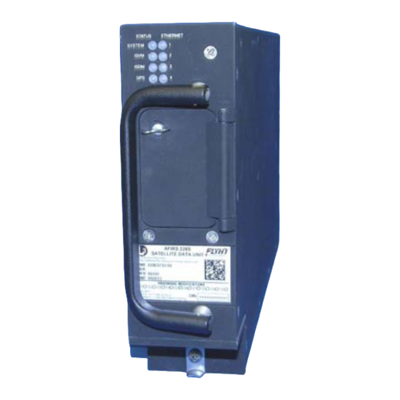
Page 57: Figure 3-1 - Airbus Iridium Satcom System Satellite Data Unit (Sdu)
Airbus Iridium SATCOM System EQUIPMENT SPECIFICATIONS This section describes the mechanical and environmental specifications of the components of the Airbus Iridium SATCOM System. 3.1 Satellite Data Unit (SDU) This section describes the mechanical and environmental specifications of the components of the Satellite Data Unit (SDU) –... - Page 58 Airbus Iridium SATCOM System 3.1.1 General The SDU is housed in an ARINC 600 2MCU enclosure, which is designed to be mounted in a standard ARINC 600 mounting tray. See Figure 3-2 for an outline of this component. Figure 3-2 – SDU Outline Drawing (dimensions in [millimeters] and inches) 3.1.2 Mechanical Specifications Dimensions: 7.81”...
-
Page 59: Figure 3-3 - Airbus Iridium Satcom System Sdu Configuration Module (Scm)
Airbus Iridium SATCOM System Mounting: ARINC 600 2MCU Mounting Tray Rear Mating Connector: Size 2 ARINC 600 Receptacle Radiall P/N: NSXN2P201S0004 Maintenance Connector: RJ45 (8P8C) Modular Connector Jack ® Flash Card: CompactFlash (Type I or Type II) 3.1.3 Environmental Specifications – Airbus Iridium SATCOM System Refer to Appendix C –... -
Page 60: Mechanical Specifications
Airbus Iridium SATCOM System Typically, the SCM will be mounted on or near the ARINC 600 mounting tray used for the SDU. See Figure 3-4 for an outline of this component. Figure 3-4 – SCM Outline Drawing (dimensions in [millimeters] and inches) 3.2.2 Mechanical Specifications Dimensions: 1.00”... -
Page 61: Figure 3-5 - Scm Oblique View
Airbus Iridium SATCOM System Figure 3-5 – SCM Oblique View (Note 1: Resistance between mounting plate and module not to exceed 20 milli-ohms. Also, resistance between mounting plate and aircraft structure not to exceed 20 milli-ohms.) Figure 3-6 – SCM Connector View Showing Location of Pin 1 (Note 2: Connector is a 9-pin D-Sub, P/N ABS1145A09P03B.) 165E5733-00 L-3 Aviation Recorders Proprietary... -
Page 62: Figure 3-7 - Airbus Iridium Satcom System Antenna
Airbus Iridium SATCOM System 3.2.3 Environmental Specifications Refer to Appendix C – Environmental Qualification Forms for environmental testing conditions, categories and descriptions of the conducted tests of the SCM. 3.3 Airbus Iridium SATCOM System Satellite Antenna The antenna is a Commercial Off the Shelf (COTS) unit that is mounted on the top of the aircraft’s fuselage –... -
Page 63: Figure 3-8 - Iridium Antenna Coaxial Cable And Connectors
Airbus Iridium SATCOM System 3.4 Antenna Coaxial Cable For details on the selection and installation of the antenna coaxial cable, please see Section 4.3.4, which provides recommended coaxial cable types to be used which meet the Airbus Iridium SATCOM System requirements. Figure 3-8 illustrates the Iridium antenna coaxial cable and connectors. Figure 3-8 –... -
Page 64: Table 3-1 - J1A Top Plug (Tp) Insert
Airbus Iridium SATCOM System SDU Rear Connector (J1) Table 3-1 – J1A Top Plug (TP) Insert Ethernet Ethernet Ethernet Ethernet Ethernet Ethernet Ethernet Ethernet Ethernet Ethernet Ethernet Ethernet Ethernet Ethernet Ethernet Ethernet 165E5733-00 L-3 Aviation Recorders Proprietary Issue, Rev. 02 21 January 2014 Page 27... -
Page 65: Table 3-2 - J1B Middle Plug (Mp) Insert
Airbus Iridium SATCOM System Table 3-2 – J1B Middle Plug (MP) Insert No. 1 No. 1 No. 1 No. 1 A429Rx A429Rx A429Tx A429Tx Ext. 1 Ext. 1 Ext. 1 Ext. 1 Mic Audio Mic Audio Audio Out Audio Out No. -
Page 66: Figure 3-9 - Sdu Connector Map
Airbus Iridium SATCOM System Table 3-3 – J1C Bottom Plug (BP) Insert Pin Size Description Not Used Primary 28 VDC Power Input Power Ground Not Used Not Used Not Used Not Used Chassis Ground Not Used Not Used Not Used Not Used Iridium/GPS Antenna Figure 3-9 –... -
Page 67: Arinc 429 Digital Serial Bus Input
Airbus Iridium SATCOM System 3.5.3 ARINC 429 Digital Serial Bus Input Quantity: Format: DITS, ARINC 429 Low or high speed Low Speed Data Rate: 12.5 Kbps ± 1% High Speed Data Rate: 100 Kbps ± 1% SSM/SDI/Data Definition: Software Selectable Protocols 3.5.4 ARINC 429 Digital Serial Bus Output Quantity: Format:... -
Page 68: Discrete Outputs
Airbus Iridium SATCOM System 3.5.7 Discrete Outputs Each discrete output transitions between an ‘Open Circuit’ (high-impedance-to-ground) and a ‘Closed Circuit’ (low-impedance-to-ground) state to indicate a change in output logic. Quantity: 8 Configurable ‘Open Circuit’ Impedance: >100 kΩ ‘Open Circuit’ Voltage (Max.): 36 VDC ‘Closed Circuit’... -
Page 69: Table 3-4 - Arinc 429 Receiver Protocols - Atsu/Fwc
Airbus Iridium SATCOM System Sidetone: Provided by System to Interphone Output Sidetone Level: Software Configurable Audio Band Pass: 300 – 3400 Hz 3.5.10 Iridium / GPS Antenna Coaxial Cable Insertion Loss (Max.): 3 dB @ 1626.5 MHz 3.6 SDU Maintenance Connector (J2) The Airbus Iridium SATCOM System SDU provides an RJ-45 Maintenance Port connector on the front panel which provides for Ethernet connection to Ground Service Equipment (GSE) e.g. -
Page 70: Table 3-5 - Arinc 429 Receiver Protocols - Cfds
Airbus Iridium SATCOM System Table 3-5 – ARINC 429 Receiver Protocols – CFDS Source: Airbus CFDS Speed: Low (Configurable) Label Parameter Format Transmit Rate Time (UTC) Flight Phases Aircraft Configuration (Printer, ACARS, etc.) Discrete word Aircraft Type Discrete word Aircraft Configuration (ATSU2, ATSU1) Discrete word 120 ms... -
Page 71: Table 3-7 - Arinc 429 Receiver Port Monitoring
Airbus Iridium SATCOM System 3.9 ARINC 429 Receiver Activity Status Defines the criteria the Airbus Iridium SATCOM System uses for determining whether a receiver port is active. A bus is generally declared active when 4 consecutive words at the specified rate are received, and declared inactive when 4 consecutive samples fail. -
Page 72: Table 3-9 - Arinc 429 Transmitter Protocols Sdu - Mcdu
Airbus Iridium SATCOM System Table 3-9 – ARINC 429 Transmitter Protocols SDU – MCDU 3.10.2 From SDU to MCDU Destination: ARINC 739A MCDU Speed: Low (Configurable) Label Parameter Format Transmit Update Rate Rate Subsystem Identifier – Equipment Identifier – MCDU Address Label for MCDU#1 MCDU Address Label for MCDU#2 MCDU Address Label for MCDU#3 Table 3-10 –... -
Page 73: Figure 4-1 - 2Mcu Mounting Tray
Airbus Iridium SATCOM System INSTALLATION CONSIDERATIONS This section provides information on the installation considerations for each of the Airbus Iridium SATCOM System components. 4.1 Satellite Data Unit (SDU) The SDU is housed in an ARINC 600 2MCU enclosure, which is designed to be mounted in a standard ARINC 600 mounting tray. - Page 74 Airbus Iridium SATCOM System 4.2 SDU Configuration Module (SCM) The SCM can be mounted on or near the SDU tray within 24 inches of the SDU rear connector. The SCM should be electrically bonded to the airframe (<20 milliohms). It is recommended that the SCM be located to provide easy access to the cover if ever the SIM card requires replacement.
-
Page 75: Figure 4-2 - Iridium Antenna, Outline And Dimensions
Airbus Iridium SATCOM System Testing was performed to DO-160F, MIL-STD-810, EN-60068, ISO-2669, and the applicable ABDs unless otherwise noted. Temperature: -55° C (-67° F); to +85° C (+185° F) Altitude: -100 to +55,000 FT Vibration: 10 G’s (DO-160D/E F2-AB) Electrical Specifications ... -
Page 76: Figure 4-3 - Iridium Antenna, Gasket
Airbus Iridium SATCOM System 4.3.2 Antenna Mounting A .020 Thick Conductive Gasket is provided. L-3 recommends using (4) screws, MS24693-C274 for mounting the Airbus Iridium Antenna – see Figure 4-3. Figure 4-3 - Iridium Antenna, Gasket 4.3.3 Coaxial Cable Iridium SATCOM System Coaxial Cable: This is an RF Cable designed to cover the frequency range from 1565 MHz to 1626.5 MHz for Iridium transmit / receive operations and GPS reception. -
Page 77: Figure 4-4 - Iridium Antenna Coaxial Cable
Airbus Iridium SATCOM System The antenna coaxial specifications are listed below: Weight (Typical) 024E5733-01 - 1.633 kg (57.6 oz) 024E5733-02 – 1.497 kg (52.8 oz) 024E5733-03 – 1.470 kg (51.8 oz) Overall Dimensions (Typical) Length: 024E5733-01 – 11.3 m (445.0 inches) 024E5733-02 –... -
Page 78: Satcom Installation Materials
Airbus Iridium SATCOM System SATCOM INSTALLATION MATERIALS In addition to the Airbus Iridium SATCOM System LRUs (SDU and SCM), the materials described in this section are generally required as part of a typical Airbus Iridium SATCOM System installation. Note: The system integrator is responsible to ensure that all installation materials used meet the regulatory requirements for the intended aircraft installation environment. -
Page 79: Figure 6-1 - Primary Power, Antenna, And Scm Interface
Airbus Iridium SATCOM System SYSTEM INTERFACE WIRING This section provides information on the system interface wiring required for the Airbus Iridium SATCOM System. 6.1 General All wire types and installation practices must comply with the requirements for the aircraft. Unless otherwise noted, minimum wire size is 22 AWG for standard copper wire or 24 AWG for high strength copper alloy wire. -
Page 80: Receiver Protocols
Airbus Iridium SATCOM System 6.3.1 Receiver Protocols Each of the ARINC 429 receivers can be configured in software for the proper protocol of the external aircraft system to which it is interfaced. Below is a list of the available ARINC 429 receiver protocols. (See §3.8 for the label specifications for each receiver protocol.) Once a protocol (except “None”... -
Page 81: Figure 6-2 - Mcdu Interface
Airbus Iridium SATCOM System 6.4 MCDU If an ARINC 739A MCDU is installed, MCDU 1 should be connected to ARINC 429 Tx 1 and ARINC 429 Rx 1. For MCDU 2 and 3, ARINC 429 Rx ports 2 and 3 are used as shown in Figure 6-2, but any Rx port from 2 to 16 may be used. -
Page 82: Figure 6-3 - Acars Atsu Interface
Airbus Iridium SATCOM System 6.5 ACARS ATSU The ACARS ARINC 429 Tx interface provides safety-services data functionality for the Airbus Iridium SATCOM System. It is recommended that if the ACARS ATSU ARINC 429 Rx connection will not be utilized, that the wires be capped and stowed near the connectors as shown. ARINC 429 Rx port 4 is shown in Figure 6-3, but any Rx port from 2 to 16 may be used. -
Page 83: Figure 6-4 - Cfdiu Interface
Airbus Iridium SATCOM System 6.6 CFDIU Interface The SDU communicates with the Airbus Centralized Fault Display Interface Unit (CFDIU) over two ARINC 429 Low Speed busses, (1) input and (1) output as shown in Figure 6-4 Figure 6-4 – CFDIU Interface 6.7 Date, Time and Position The Airbus Iridium SATCOM System uses date, time and position information for numerous purposes, including information tags attached to various reports and events. -
Page 84: Figure 6-5 - Serial Port Interface
Airbus Iridium SATCOM System When configured for RS-232 mode, the serial ports support software (Xon/Xoff) and hardware (RTS/CTS) handshaking. If hardware handshaking is not being used, the RTS and CTS pins do not need to be connected. Figure 6-5 – Serial Port Interface 6.9 Ethernet The Airbus Iridium SATCOM System has four Ethernet ports (see Figure 6-6). -
Page 85: Figure 6-6 - Ethernet Interface
Airbus Iridium SATCOM System Monitored Unused Ethernet ports should be configured as “None.” A “Monitored” port is one where the system expects an active link and it will generate a fault if the Ethernet link to the external system is not available. -
Page 86: Function Assignment
Airbus Iridium SATCOM System When any of the LGCIU discrete inputs are in the inactive state, the aircraft is considered as ‘in the air. 6.10.2 Function Assignment The discrete inputs are software configurable. Once a function is selected for any given input, it is no longer available for assignment to any of the other inputs. -
Page 87: Audio Integrating System
Airbus Iridium SATCOM System Figure 6-7 – Discrete Input Interfaces 6.11 Discrete Outputs The Airbus Iridium SATCOM System has 8 configurable Discrete Outputs, each of which is software- configurable for Active High or Active Low logic and the assigned function. The Discrete Outputs use ‘Open-Closed’... -
Page 88: Figure 6-8 - Latched Acp Audio Interface
Airbus Iridium SATCOM System Mic On Input The ‘Mic On’ function is dedicated as a ‘Latched ACP’ mode; therefore, Voice Extension 1 (Mic/Phone input) will answer an incoming call when the ‘Mic On’ input transitions to the active state. Once a call is in progress, the microphone audio channel will function as long as the ‘Mic On’... -
Page 89: Satcom System Configuration
Airbus Iridium SATCOM System SATCOM SYSTEM CONFIGURATION You configure the Airbus Iridium SATCOM System Satellite Data Unit (SDU) via Ethernet using a laptop, web browser, and the AFIRS Maintenance User Interface (MUI). Note: The MUI only accepts English-language characters and numbers. IMPORTANT: This manual provides information on how to connect to the Maintenance Port and access the Maintenance User Interface (MUI). -
Page 90: Accessing The Maintenance User Interface (Mui)
Airbus Iridium SATCOM System 7.1 Accessing the Maintenance User Interface (MUI) You access the AFIRS MUI by connecting an Ethernet cable to the Maintenance Port of the SDU. Alternatively, as described in section 6.9, Ethernet Port 1A can be used. Also, if an Electronic Flight Bag (EFB) with a supported web browser installed is connected to one of the rear Ethernet port connections, the EFB can be used as an AFIRS maintenance terminal and a laptop is not required. -
Page 91: Home Page Tab Descriptions
Airbus Iridium SATCOM System Figure 7-2 – Home Page – General Tab The default view opens to the Home page General tab (see Figure 7-2) which displays the following information: Login area Menu of available links to pages accessible to various users upon login Tabs: General, ARINC, and Discrete In System and Link status display area System information data display area... -
Page 92: Faults Page
Airbus Iridium SATCOM System ISVM LINK: Yellow (NO LINK) no Iridium link if CSQ (Channel Signal Quality) is 0-1; Green (OK) if CSQ is 2-5 ISDM LINK: Yellow (NO LINK) no Iridium link if CSQ (Channel Signal Quality) is 0-1; Green (OK) if CSQ is 2-5 GPS LINK: Yellow (NO FIX), Green (OK) The ARINC tab displays the status of the 16 ARINC 429 RX channels. -
Page 93: Part Numbers Page
Airbus Iridium SATCOM System 7.1.3 Part Numbers Page The Part Numbers page provides the status of the software (Figure 7-5) and hardware configuration (Figure 7-6) of the Airbus Iridium SATCOM System. Figure 7-5 – Part Number Page (Software Tab) Figure 7-6 – Part Number Page (Hardware Tab) 165E5733-00 L-3 Aviation Recorders Proprietary Issue, Rev. -
Page 94: Figure 7-7- Entering Maintenance Mode Message
Airbus Iridium SATCOM System 7.2 Entering Maintenance Mode In order to enter Maintenance Mode, the aircraft must be deemed ‘On-Ground’. If the aircraft is deemed ‘In-Air’, the [Enter Maintenance Mode] button will be or will become unavailable. If the aircraft status changes to ‘In-Air’ while in Maintenance Mode, the system will reboot automatically and return to Operational Mode. -
Page 95: Entering Maintenance Mode
Airbus Iridium SATCOM System The Home screen appears as shown in Figure 7-8. The SYSTEM status indicates Yellow (blank). Note: Entering Maintenance Mode disables all MCDU functions. Figure 7-8 – Maintenance Mode Initial Display Screen To exit Maintenance Mode: Upon completion of uploading of data or software files or modifying parameters, click Exit Maintenance Mode for the changes to take effect –... -
Page 96: Figure 7-9 - Maintenance Mode Exit Screen
Airbus Iridium SATCOM System Figure 7-9 – Maintenance Mode Exit Screen Figure 7-10 – System Restart Screen Note: Exiting Maintenance Mode enables all MCDU functions. If the aircraft status changes to ‘In-Air’ while in Maintenance Mode, the system will reboot automatically and return to Operational Mode, disregarding incomplete file uploads. -
Page 97: Maintenance Mode Menu Descriptions
Airbus Iridium SATCOM System 7.2.1 Maintenance Mode Menu Descriptions Entering Maintenance Mode provides the Upgrades page to the Maintenance User and Administrator User. 1. Click Upgrades to upload software or data files. The screen shown in Figure 7-11 will be displayed. - Page 98 Airbus Iridium SATCOM System 7. Maintenance User can modify only 5 ORT parameters: a. Click ORT (Owner Requirements Table) to configure customized settings for specific aircraft and or operator requirements. 8. Administrator User can modify any UAT parameter: a. Click UAT (User Access Table) to configure user access privileges. 9.
-
Page 99: Table 7-1 - Read Privileges By Role
Airbus Iridium SATCOM System Table 7-1 - Read Privileges by Role Read Privileges Status and Part Numbers Configurations Part Numbers: ICT P/N, ORT P/N, ISVM F/W Ver., Status: Operating Mode, ISDM F/W Ver., UAT GPS Source, Configured ARINC 429 Rx S/W P/N, ADB Phone Number, ISVM IMEI, Channels Status Discrete Inputs SDU P/N, (User ISDM IMEI, Status LEDs (Active/ Status (Active/ Fault SCM P/N, (Address Access Roles (System, GPS, ISVM, ISDM) ... -
Page 100: Table 7-2 - Download Privileges By Role
Airbus Iridium SATCOM System Table 7-2 - Download Privileges by Role Download Privileges Logs Configurations ADB UAT On‐ In‐Air Ground Status (Link (Address (User Access Roles Failures Faults Faults Changes) Debug ICT ORT Book) Table) Guest (no login required) No Data Collector Yes Maintenance Yes ... -
Page 101: Table 7-3 - Modify Privileges By Role
Airbus Iridium SATCOM System Table 7-3 – Modify Privileges by Role Modify Privileges Modifications Software/Data Loading (Upload) ADB (User (User ORT ICT Access S/W ORT (Address Access Roles Parameters Parameters Address Book Table) Upgrades ICT (Complete) Book) Table) Guest (no login required) No No Data Collector No ... -
Page 102: Configuring The Airbus Iridium Satcom System
Airbus Iridium SATCOM System 7.3 Configuring the Airbus Iridium SATCOM System This section provides basic information on how to configure the Airbus Iridium SATCOM System. User access privileges are required to modify parameters as follows: Maintenance User – 5 ORT parameters Administrator User –... -
Page 103: Address Book
Airbus Iridium SATCOM System To view the Address Book in the MUI: 1. In Operational Mode, log in as Maintenance User or Administrator User. 2. Click Address Book to display the Address Book entries (see Figure 7-12). Figure 7-12 – Address Book 3. -
Page 104: Figure 7-13 - Ort Screen
Airbus Iridium SATCOM System The file name of an up-loadable ORT file has a part number; for example, ‘852E5927-00.bin’. It is version-controlled and the CRC is calculated and displayed during the upload process for verification. The default file name of a downloaded ORT file is ‘ort.bin’. Figure 7-13 –... -
Page 105: Installation Configuration Table (Ict)
Airbus Iridium SATCOM System 6. OTHER CALL PARAMETERS – ALLOW LOW PRIORITY CALLS IN COCKPIT: Low- priority calls are considered PUBLIC or Priority 4. If set to YES, low-priority calls can be received in the cockpit, and low-priority calls can be placed from the cockpit. If set to NO, low-priority incoming calls will not ring in the cockpit, and no low-priority calls can be placed from the cockpit. -
Page 106: Figure 7-14 - Uat Page
Airbus Iridium SATCOM System Figure 7-14 – UAT Page To access and modify UAT parameters: 1. Log in with user name and password as Administrator User 2. Click Enter Maintenance Mode. Note: The aircraft status must be “On-Ground” to be able to Enter Maintenance Mode. 3. -
Page 107: Upgrade Materials
Airbus Iridium SATCOM System 7.4 Upgrading Airbus Iridium SATCOM System Software The Airbus Iridium SATCOM System software is field-upgradeable using the Upgrade function of the MUI in Maintenance Mode. One of the following user privileges is required to login and enter Maintenance Mode to upload software and data files: ... -
Page 108: Figure 7-15 - Software Upgrade Progress
Airbus Iridium SATCOM System Figure 7-15 – Software Upgrade Progress Note: Incompatible files will be rejected. The progress bars turn red, and an error message displays next to the progress bars. Click Reset to restart the upgrade process. If you uploaded an incorrect file, but have not yet clicked Apply, click Reset to restart the upgrade process. -
Page 109: Figure 7-17 - Exit Maintenance Mode Message
Airbus Iridium SATCOM System To activate the newly installed software, you must Exit Maintenance Mode and restart the SDU. 5. To exit Maintenance mode, click Exit Maintenance Mode at the top-right corner of the MUI screen, A confirmation message displays prompting to confirm that you want to exit Maintenance Mode (see Figure 7-17). -
Page 110: Exiting Maintenance Mode
Airbus Iridium SATCOM System 7. When the restart is complete, verify that the SDU is in Operational Mode and functioning as expected. To verify that the correct software version and configurations have been loaded, check the following: a. From the Home page, click on the General, ARINC, and Discrete In tabs to review the system and link status, and the status of the ARINC 429 Rx and Discrete In connections. -
Page 111: Figure 7-20 - Restart Screen
Airbus Iridium SATCOM System Figure 7-20 – Restart Screen 5. Once the system reboots to Operational Mode, verify your changes and confirm that the correct software and data files have been installed. 6. Click the Part Numbers page and review the Software tab for the correct Part Numbers 7. -
Page 112: Maintenance And Checkout
Airbus Iridium SATCOM System MAINTENANCE AND CHECKOUT This section provides instructions on post-installation checkout procedures and information on Instructions for Continued Airworthiness. 8.1 Post-Installation Checkout 8.1.1 Before Power-On Tests 1. Before installing the SDU in the mounting tray, confirm that all aircraft interface wiring is correct as per the aircraft wiring integration design. -
Page 113: Aircraft Systems Interface Tests
Airbus Iridium SATCOM System 8.1.2 Aircraft Systems Interface Tests Note: The tests listed in this section are generic in nature and are not intended to be used as a test plan for any specific aircraft installation. They should only be used by the aircraft systems integrator as a guide in developing the correct and complete aircraft-specific integration tests. -
Page 114: Operational System Tests
Airbus Iridium SATCOM System 8.1.2.4 Ethernet Port Tests Confirm Ethernet connectivity to each Ethernet device as follows: Confirm that the SDU front panel ETHERNET LEDs for the connected ports are green. Flashing green indicates data is being transferred. Perform any tests specific to the connected system to confirm that it is communicating with the SDU over the Ethernet port. -
Page 115: Emi Tests
Airbus Iridium SATCOM System 8.1.3.3 SATCOM Voice Tests 1. Confirm that the MCDU SATCOM MAIN MENU page displays Ready to Connect. 2. Place an air-to-ground call by using the MCDU. Confirm proper MCDU indications for a call in progress. 3. Terminate the call from the cockpit. Confirm proper cockpit indications and return to Ready to Connect state. -
Page 116: Appendix A – Wiring Diagram
Airbus Iridium SATCOM System Appendix A – Wiring Diagram (follows on next 3 pages) 165E5733-00 L-3 Aviation Recorders Proprietary Issue, Rev. 02 21 January 2014 Page 79... - Page 117 Airbus Iridium SATCOM System 165E5733-00 L-3 Aviation Recorders Proprietary Issue, Rev. 02 21 January 2014 Page 80...
- Page 118 Airbus Iridium SATCOM System 165E5733-00 L-3 Aviation Recorders Proprietary Issue, Rev. 02 21 January 2014 Page 81...
- Page 119 Airbus Iridium SATCOM System 165E5733-00 L-3 Aviation Recorders Proprietary Issue, Rev. 02 21 January 2014 Page 82...
-
Page 120: Appendix B – Ort Worksheet
Airbus Iridium SATCOM System Appendix B – ORT Worksheet ORT Group ORT Parameter Name Value NORTH AMERICAN Air to Ground Call Progress Tones EUROPEAN Calls YES Allow Manual Extension 1 NO Dialing YES Other Call Allow Low Priority Calls in Cockpit NO Parameters NONE Safety Services Additional ACARS Header Parameter ARINC Airbus Iridium SATCOM ... - Page 121 Airbus Iridium SATCOM System THIS PAGE INTENTIONALLY LEFT BLANK 165E5733-00 L-3 Aviation Recorders Proprietary Issue, Rev. 02 21 January 2014 Page 84...
-
Page 122: Appendix C – Environmental Qualification Forms
Airbus Iridium SATCOM System Appendix C – Environmental Qualification Forms The following forms are provided for the Airbus Iridium SATCOM System SDU and Airbus Iridium SATCOM System SCM, and Airbus Iridium Antenna System respectively. 165E5733-00 L-3 Aviation Recorders Proprietary Issue, Rev. 02 21 January 2014 Page 85... -
Page 123: January
Airbus Iridium SATCOM System Environmental Qualification Form RTCA DO-160G Model: AFIRS 228S Product: Satellite Data Unit and Satellite Control Module Part Number: 228E5733-00 Manufacturer: L-3 Communications, Aviation Recorders 418E5733-00 100 Cattlemen Road, Sarasota FL, 34232 P.O. Box 3041, Zip Code 34230-3041 TSO Number: Manufacturer's Specification and/or Other Applicable Specifications: Aviation Recorders QTP #905-E5750-34... - Page 124 Airbus Iridium SATCOM System TEST Conditions Description of Conducted Tests STANDARD Altitude 4.6.1 +15,000 feet Decompression 4.6.2 +8,000 feet +50,000 feet Overpressure 4.6.3 Equipment tested at 183 kPa and 199 kPa (Absolute Pressure) Temperature Variation DO-160G, Equipment tested to Category B. Section 5 ABD100.1.2 G Humidity...
- Page 125 Airbus Iridium SATCOM System TEST Conditions Description of Conducted Tests STANDARD Fluids Susceptibility DO-160G Equipment tested to Category F, for: Section 11.4.1 Cleaning Agents Disinfectants ABD100.1.6 D Extinguishing Agents Sections 4.7 Insecticides and 4.8 Heat Transfer Fluids ...
- Page 126 Airbus Iridium SATCOM System TEST Conditions Description of Conducted Tests STANDARD Induced Signal Susceptibility DO-160G Equipment tested to Category ZW. Section 19.0 ABD100.1.2 G Section 3.4.4 19.3.1 Magnetic Fields Equipment 19.3.3 Cables Magnetic Fields 19.3.4 Cables Electric Fields 19.3.5 Cables Spikes Electrostatic Discharge Equipment tested Category B...
- Page 127 Airbus Iridium SATCOM System L-3 Aviation Recorders 100 Cattlemen Road Sarasota, FL 34232 Telephone: 1-941-371-0811 Fax: 1-941-377-5591 E-mail support: DLAR-aviationproducts@L-3com.com Website: http://www.L-3ar.com 165E5733-00 L-3 Aviation Recorders Proprietary Issue, Rev. 02 21 January 2014 Page 90...
-
Page 128: Table 1-1 - Part Numbers
COMPONENT MAINTENANCE MANUAL AIRBUS IRIDIUM SATCOM SYSTEM AIRBUS IRIDIUM SATCOM SYSTEM IRIDIUM SATCOM SYSTEM PART NUMBERS SDU - 228E5733-00 SCM - 418E5733-00 COMPONENT MAINTENANCE MANUAL WITH ILLUSTRATED PARTS LIST P/N: 165E5733-10 IN ACCORDANCE WITH TSO C-159a VENDOR CODE: 06141 23-28-01 Revision 1 Jan. - Page 129 AVIATION RECORDERS COMPONENT MAINTENANCE MANUAL AIRBUS IRIDIUM SATCOM SYSTEM EXPORT CONTROL STATEMENT IRIDIUM SATCOM TECHNOLOGY / DATA: “This Iridium SATCOM System Technical Data is being exported from the United States in accordance with the Export Administration Regulations (ECCN #7A994), No License Required (NLR). Diversion contrary to U.S.
- Page 130 AVIATION RECORDERS COMPONENT MAINTENANCE MANUAL AIRBUS IRIDIUM SATCOM SYSTEM GENERAL This product and related documentation must be reviewed for familiarization with safety markings and instructions before operation. This instrument was constructed in an ESD (electro – static discharge) protected environment. This is be cause most of the semiconductor devices used in this instrument are susceptible to damage by static dis charge.
- Page 131 AVIATION RECORDERS COMPONENT MAINTENANCE MANUAL AIRBUS IRIDIUM SATCOM SYSTEM THIS PAGE IS INTENTIONALLY LEFT BLANK 23-28-01 Title Page iv Jan. 21/14...
- Page 132 AVIATION RECORDERS COMPONENT MAINTENANCE MANUAL AIRBUS IRIDIUM SATCOM SYSTEM SERVICE BULLETIN LIST SERVICE BULLETIN DATE EFFECTIVITY DESCRIPTION 23-28-01 Service Bulletin Page v Jan. 21/14...
- Page 133 AVIATION RECORDERS COMPONENT MAINTENANCE MANUAL AIRBUS IRIDIUM SATCOM SYSTEM THIS PAGE IS INTENTIONALLY LEFT BLANK 23-28-01 Service Bulletin Page vi Jan. 21/14...
- Page 134 AVIATION RECORDERS COMPONENT MAINTENANCE MANUAL AIRBUS IRIDIUM SATCOM SYSTEM RECORD OF CHANGES Issue Revision Date of Comments Change Initial Dec. 15/13 Initial issue of AB Iridium SATACOM CMM. Includes all sections, per ATA100. Jan. 21/14 Corrected part numbers. 23-28-01 Record of Changes Page vii Jan.
- Page 135 AVIATION RECORDERS COMPONENT MAINTENANCE MANUAL AIRBUS IRIDIUM SATCOM SYSTEM THIS PAGE IS INTENTIONALLY LEFT BLANK 23-28-01 Record of Changes Page viii Jan. 21/14...
- Page 136 AVIATION RECORDERS COMPONENT MAINTENANCE MANUAL AIRBUS IRIDIUM SATCOM SYSTEM RECORD OF REVISIONS REV. INSERTION REV. INSERTION REV. INSERTION DATE DATE DATE 23-28-01 Record of Revisions Page ix Jan. 21/14...
- Page 137 AVIATION RECORDERS COMPONENT MAINTENANCE MANUAL AIRBUS IRIDIUM SATCOM SYSTEM THIS PAGE IS INTENTIONALLY LEFT BLANK 23-28-01 Record of Revisions Page x Jan. 21/14...
- Page 138 AVIATION RECORDERS COMPONENT MAINTENANCE MANUAL AIRBUS IRIDIUM SATCOM SYSTEM LIST OF EFFECTIVE PAGES Section Page Date Section Page Date Title Page Introduction Jan. 21/14 Jan. 21/14 Jan. 21/14 Jan. 21/14 Jan. 21/14 Jan. 21/14 Jan. 21/14 Jan. 21/14 Jan. 21/14 Jan.
- Page 139 AVIATION RECORDERS COMPONENT MAINTENANCE MANUAL AIRBUS IRIDIUM SATCOM SYSTEM LIST OF EFFECTIVE PAGES Section Page Date Section Page Date Jan. 21/14 Jan. 21/14 Repair Jan. 21/14 Jan. 21/14 Jan. 21/14 Jan. 21/14 Jan. 21/14 Assembly Special Tools, Fixtures and Equipment Jan.
- Page 140 AVIATION RECORDERS COMPONENT MAINTENANCE MANUAL AIRBUS IRIDIUM SATCOM SYSTEM TABLE OF CONTENTS INTRODUCTION SUBJECT/DESCRIPTION PAGE GENERAL......................... 1 ACRONYMS AND ABBREVIATIONS ................1 DOCUMENT REQUIREMENTS ..................4 REQUIRED DOCUMENTS REFERENCE DOCUMENTS MAINTENANCE PHILOSOPHY ..................6 COMPONENT MAINTENANCE MANUAL (CMM) DESCRIPTION ........7 FRONT MATTER DESCRIPTION AND OPERATION TESTING AND TROUBLESHOOTING...
- Page 141 AVIATION RECORDERS COMPONENT MAINTENANCE MANUAL AIRBUS IRIDIUM SATCOM SYSTEM CLEANING GENERAL........................401 CHECK GENERAL........................501 REPAIR GENERAL........................601 ASSEMBLY GENERAL........................701 FITS AND CLEARANCES SUBJECT/DESCRIPTION PAGE GENERAL........................801 EQUIPMENT SPECIFICATIONS ................... 801 SATELLITE DATA UNIT (SDU) SDU CONFIGURATION MODULE (SCM) IRIDIUM ANTENNA SYSTEM COAXIAL ANTENNA CABLE ASSEMBLY SPECIAL TOOLS, FIXTURES AND EQUIPMENT...
-
Page 142: Figure 2-1 - Airbus Iridium Satcom System Operational Concept
AVIATION RECORDERS COMPONENT MAINTENANCE MANUAL AIRBUS IRIDIUM SATCOM SYSTEM LIST OF FIGURES FIGURE TITLE PAGE Airbus Iridium SATCOM System Operational Concept Figure 1. Airbus Iridium SATCOM System Block Diagram Figure 2. Satellite Data Unit (SDU) Assembly Drawing Figure 3. Part Number: 228E5733-00 SDU Configuration Module (SCM) Assembly Drawing Figure 4. - Page 143 AVIATION RECORDERS COMPONENT MAINTENANCE MANUAL AIRBUS IRIDIUM SATCOM SYSTEM THIS PAGE IS INTENTIONALLY LEFT BLANK 23-28-01 Table of Contents Page xvi Jan. 21/14...
- Page 144 AVIATION RECORDERS COMPONENT MAINTENANCE MANUAL AIRBUS IRIDIUM SATCOM SYSTEM INTRODUCTION 1. GENERAL This Component Maintenance Manual (CMM) describes the components for the Airbus Iridium SATCOM System. The system includes a Satellite Data Unit (SDU), p/n: 228E5733-00, an SDU Configuration Module (SCM), p/n: 418E5733-00, along with an Iridium Antenna, p/n: 009E5733-00, and Coaxial Antenna Cable assembly, p/n: 024E5733- XX.
- Page 145 AVIATION RECORDERS COMPONENT MAINTENANCE MANUAL AIRBUS IRIDIUM SATCOM SYSTEM Acronym Definition BITE Built-In Test Equipment Compact Flash CFDS Centralized Fault Display System (Airbus) CNSSA Core Non-Safety Services Application Clear To Send DITS Digital Information Transfer System Date Time Position Electronic Flight Bag Electronics Industry Association Federal Aviation Administration Firmware...
- Page 146 AVIATION RECORDERS COMPONENT MAINTENANCE MANUAL AIRBUS IRIDIUM SATCOM SYSTEM Acronym Definition ISVM Iridium Satellite Voice Modem LGCIU Landing Gear Control Interface Unit Light Emitting Diode Line Replaceable Unit Line Select Key MCDU Multi-Purpose Control and Display Unit MOPS Minimum Operational Performance Specifications Maintenance User Interface Normally Closed NGSS...
- Page 147 AVIATION RECORDERS COMPONENT MAINTENANCE MANUAL AIRBUS IRIDIUM SATCOM SYSTEM Acronym Definition Safety Service Application Signed Status Matrix Software Telecommunications Industry Association Threaded Neill–Concelman Transmit Technical Standard Order User Access Table Coordinated Universal Time Volts Alternating Current Volts Direct Current Words Per Second 3.
- Page 148 AVIATION RECORDERS COMPONENT MAINTENANCE MANUAL AIRBUS IRIDIUM SATCOM SYSTEM B. REFERENCE DOCUMENTS The following documents are listed for reference only. Table 2. Reference Document List Ref. Document Number Description • ANSI/TIA/EIA-232- Interface Between Data Terminal Equipment and Data Circuit- F-1997 Terminating Equipment Employing Serial Binary Data Interchange •...
- Page 149 AVIATION RECORDERS COMPONENT MAINTENANCE MANUAL AIRBUS IRIDIUM SATCOM SYSTEM Ref. Document Number Description • RTCA/DO-160G Environmental Conditions and Test Procedures for Airborne Equipment • RTCA/DO-214 Audio Systems Characteristics and Minimum Operational Performance Standards for Aircraft Audio Systems and Equipment • RTCA/DO-262A Minimum Operational Performance Standards for Avionics Supporting Next Generation Satellite Systems (NGSS)
- Page 150 AVIATION RECORDERS COMPONENT MAINTENANCE MANUAL AIRBUS IRIDIUM SATCOM SYSTEM 5. COMPONENT MAINTENANCE MANUAL (CMM) DESCRIPTION This CMM consists of a single volume. The manual conforms to the intent and form of Air Transport Association of America (ATA) Specification 100, Revision 36. The manual is written for an audience of intermediate- and depot-level maintenance technicians;...
- Page 151 AVIATION RECORDERS COMPONENT MAINTENANCE MANUAL AIRBUS IRIDIUM SATCOM SYSTEM H. ASSEMBLY This section is not applicable under the current maintenance philosophy for the SDU and SCM units. These units are not field-repairable, and as such, must be returned to the L-3AR factory for testing and repair should an LRU fail. I.
- Page 152 AVIATION RECORDERS COMPONENT MAINTENANCE MANUAL AIRBUS IRIDIUM SATCOM SYSTEM DESCRIPTION AND OPERATION 1. SYSTEM OVERVIEW Refer to Figure 1. The Airbus Iridium SATCOM System comprises a portion of the aircraft avionics, or “Aircraft Earth Station” (AES) required to support the "Next Generation Satellite System"...
- Page 153 AVIATION RECORDERS COMPONENT MAINTENANCE MANUAL AIRBUS IRIDIUM SATCOM SYSTEM Refer to Figure 2. The Airbus Iridium SATCOM System interfaces to various aircraft systems to monitor, record, and report the aircraft flight and system data. This data includes aircraft movement and position reports, Flight Data Monitoring (FDM) data records, engine and airframe system health and trend records and reports, and monitored parameter tolerances and exception reports.
-
Page 154: Satellite Data Unit (Sdu)
AVIATION RECORDERS COMPONENT MAINTENANCE MANUAL AIRBUS IRIDIUM SATCOM SYSTEM 2. SYSTEM ARCHITECTURE The Airbus Iridium SATCOM System consists of three Line Replaceable Units (LRUs). The core system components are the Satellite Data Unit (SDU), the SDU Configuration Module (SCM), the Iridium Antenna, and Coaxial Antenna Cable assembly. Optional components include Cabin Handset(s) (Wired or Cordless). -
Page 155: Sdu Configuration Module (Scm)
AVIATION RECORDERS COMPONENT MAINTENANCE MANUAL AIRBUS IRIDIUM SATCOM SYSTEM B. SDU CONFIGURATION MODULE (SCM) Refer to Figure 4. The SCM is a small module that is mounted near the SDU. It uses an EEPROM to store a copy of the “aircraft personality” information. The SCM also contains the Iridium SIM card, which provides access to the Iridium satellite network for the voice communications functionality. -
Page 156: Iridium Antenna System
AVIATION RECORDERS COMPONENT MAINTENANCE MANUAL AIRBUS IRIDIUM SATCOM SYSTEM C. IRIDIUM ANTENNA SYSTEM Refer to Figure 5. The antenna is a Commercial Off-The-Shelf (COTS) unit that is mounted on the top of the aircraft’s fuselage. It provides satellite connectivity for both the GPS and Iridium satellite systems. - Page 157 AVIATION RECORDERS COMPONENT MAINTENANCE MANUAL AIRBUS IRIDIUM SATCOM SYSTEM THIS PAGE IS INTENTIONALLY LEFT BLANK 23-28-01 Description and Operation Page 6 Jan. 21/14...
- Page 158 AVIATION RECORDERS COMPONENT MAINTENANCE MANUAL AIRBUS IRIDIUM SATCOM SYSTEM TESTING AND TROUBLESHOOTING 1. GENERAL This section is not applicable to this CMM. The Airbus Iridium System components: Satellite Data Unit, p/n: 228E5733-00, and SDU Configuration Module, p/n: 418E5733-00, have been designated as Level-1 non-field- repairable Line Replaceable Units.
- Page 159 AVIATION RECORDERS COMPONENT MAINTENANCE MANUAL AIRBUS IRIDIUM SATCOM SYSTEM THIS PAGE IS INTENTIONALLY LEFT BLANK 23-28-01 Testing & Fault Isolation Page 102 Jan. 21/14...
- Page 160 AVIATION RECORDERS COMPONENT MAINTENANCE MANUAL AIRBUS IRIDIUM SATCOM SYSTEM DISASSEMBLY 1. GENERAL This section is not applicable to this CMM. The Airbus Iridium System components: Satellite Data Unit, p/n: 228E5733-00, and SDU Configuration Module, p/n: 418E5733-00, have been designated as Level-1 non-field- repairable Line Replaceable Units.
- Page 161 AVIATION RECORDERS COMPONENT MAINTENANCE MANUAL AIRBUS IRIDIUM SATCOM SYSTEM THIS PAGE IS INTENTIONALLY LEFT BLANK 23-28-01 Disassembly Page 302 Jan. 21/14...
- Page 162 AVIATION RECORDERS COMPONENT MAINTENANCE MANUAL AIRBUS IRIDIUM SATCOM SYSTEM CLEANING 1. GENERAL This section is not applicable to this CMM. The Airbus Iridium System components: Satellite Data Unit, p/n: 228E5733-00, and SDU Configuration Module, p/n: 418E5733-00, have been designated as Level-1 non-field- repairable Line Replaceable Units.
- Page 163 AVIATION RECORDERS COMPONENT MAINTENANCE MANUAL AIRBUS IRIDIUM SATCOM SYSTEM THIS PAGE IS INTENTIONALLY LEFT BLANK 23-28-01 Cleaning Page 402 Jan. 21/14...
- Page 164 AVIATION RECORDERS COMPONENT MAINTENANCE MANUAL AIRBUS IRIDIUM SATCOM SYSTEM CHECK 1. GENERAL This section is not applicable to this CMM. The Airbus Iridium System components: Satellite Data Unit, p/n: 228E5733-00, and SDU Configuration Module, p/n: 418E5733-00, have been designated as Level-1 non-field- repairable Line Replaceable Units.
- Page 165 AVIATION RECORDERS COMPONENT MAINTENANCE MANUAL AIRBUS IRIDIUM SATCOM SYSTEM THIS PAGE IS INTENTIONALLY LEFT BLANK 23-28-01 Check Page 502 Jan. 21/14...
- Page 166 AVIATION RECORDERS COMPONENT MAINTENANCE MANUAL AIRBUS IRIDIUM SATCOM SYSTEM REPAIR 1. GENERAL This section is intended to contain information required to restore a worn or damaged part to a serviceable condition. However, the Airbus Iridium SATCOM System is a completely solid-state device that does not contain any electro-mechanical moving parts.
- Page 167 AVIATION RECORDERS COMPONENT MAINTENANCE MANUAL AIRBUS IRIDIUM SATCOM SYSTEM THIS PAGE IS INTENTIONALLY LEFT BLANK 23-28-01 Repair Page 602 Jan. 21/14...
- Page 168 AVIATION RECORDERS COMPONENT MAINTENANCE MANUAL AIRBUS IRIDIUM SATCOM SYSTEM ASSEMBLY 1. GENERAL This section is not applicable to this CMM. The Airbus Iridium System components: Satellite Data Unit, p/n: 228E5733-00, and SDU Configuration Module, p/n: 418E5733-00, have been designated Level-1 non-field- repairable Line Replaceable Units.
- Page 169 AVIATION RECORDERS COMPONENT MAINTENANCE MANUAL AIRBUS IRIDIUM SATCOM SYSTEM THIS PAGE IS INTENTIONALLY LEFT BLANK 23-28-01 Assembly Page 702 Jan. 21/14...
- Page 170 AVIATION RECORDERS COMPONENT MAINTENANCE MANUAL AIRBUS IRIDIUM SATCOM SYSTEM FITS AND CLEARANCES 1. GENERAL This section provides the Airbus Iridium System specifications and outline and dimensions. Since the recorder uses solid-state memory recording technology, there are no internal fits and clearances or torque values normally associated with older technology electro- mechanical tape recorder units.
- Page 171 AVIATION RECORDERS COMPONENT MAINTENANCE MANUAL AIRBUS IRIDIUM SATCOM SYSTEM SDU Specifications Dimensions: 7.81” x 2.27” x 15.02” (198.3mm x 57.7mm x 381.5mm) Weight: 7.7 lbs. (3.49 kg) Max. Material/Finish: Aluminum Alloy with Black Polyurethane Finish Mounting: ARINC 600 2MCU Mounting Tray Rear Mating Connector: Size 2 ARINC 600 Receptacle Radiall P/N: NSXN2P201S0004 Maintenance Connector: RJ45 (8P8C) Modular Connector Jack...
- Page 172 AVIATION RECORDERS COMPONENT MAINTENANCE MANUAL AIRBUS IRIDIUM SATCOM SYSTEM B. SDU CONFIGURATION MODULE (SCM) This paragraph describes the mechanical specifications of the SDU Configuration Module (SCM). Refer to Figure 802 for an outline of this component. 1) SCM Outline & Dimensions Figure 802.
- Page 173 AVIATION RECORDERS COMPONENT MAINTENANCE MANUAL AIRBUS IRIDIUM SATCOM SYSTEM C. IRIDIUM ANTENNA SYSTEM This paragraph describes the mechanical specifications of the Iridium Antenna. Refer to Figure 803 for the Outline & Dimension drawing of this component. 1) Iridium Antenna Outline & Dimensions Figure 803.
- Page 174 AVIATION RECORDERS COMPONENT MAINTENANCE MANUAL AIRBUS IRIDIUM SATCOM SYSTEM Iridium Antenna Specifications The Iridium SATCOM System Antenna is a passive antenna designed to cover the frequency range from 1565 MHz to 1626.5 MHz for Iridium transmit / receive operations and GPS reception. It is a low-profile, circular device that can be mounted directly to the aircraft fuselage.
-
Page 175: Coaxial Antenna Cable Assembly
AVIATION RECORDERS COMPONENT MAINTENANCE MANUAL AIRBUS IRIDIUM SATCOM SYSTEM Electrical Specifications Frequency: 1616.0 – 1625.5 MHz ≤ 1.5:1 VSWR: Impedance: 50-Ohms Polarization: RHCP • ≤ 3.0 db @ zenith Axial Ratio: • Power Handling: 60 Watts CW D. COAXIAL ANTENNA CABLE ASSEMBLY Refer to Figure 804. - Page 176 AVIATION RECORDERS COMPONENT MAINTENANCE MANUAL AIRBUS IRIDIUM SATCOM SYSTEM 2) Iridium Antenna Specifications Weight (Typical) • 024E5733-01 - 1.633 kg (57.6 oz) • 024E5733-02 – 1.497 kg (52.8 oz) • 024E5733-03 – 1.470 kg (51.8 oz) Overall Dimensions (Typical) • Length: 024E5733-01 –...
- Page 177 AVIATION RECORDERS COMPONENT MAINTENANCE MANUAL AIRBUS IRIDIUM SATCOM SYSTEM THIS PAGE IS INTENTIONALLY LEFT BLANK 23-28-01 Description and Operation Page 808 Jan. 21/14...
-
Page 178: Special Tools, Fixtures And Equipment
AVIATION RECORDERS COMPONENT MAINTENANCE MANUAL AIRBUS IRIDIUM SATCOM SYSTEM SPECIAL TOOLS, FIXTURES AND EQUIPMENT 1. GENERAL The Airbus Iridium System components, SDU p/n: 228E5733-00 and SCM p/n: 418E5733- 00) have been designated as Level-1 non-field-repairable Line Replaceable Units. There are no special tools, fixtures and test equipment for Level-1 maintenance for the Airbus Iridium System units. - Page 179 AVIATION RECORDERS COMPONENT MAINTENANCE MANUAL AIRBUS IRIDIUM SATCOM SYSTEM THIS PAGE IS INTENTIONALLY LEFT BLANK 23-28-01 Special Tools and Test Equipment Page 902 Jan. 21/14...
-
Page 180: Illustrated Parts List
AVIATION RECORDERS COMPONENT MAINTENANCE MANUAL AIRBUS IRIDIUM SATCOM SYSTEM ILLUSTRATED PARTS LIST 1. GENERAL The Airbus Iridium System components: Satellite Data Unit, p/n: 228E5733-00 and SDU Configuration Module, p/n: 418E5733-00, have been designated as Level-1 non-field- repairable Line Replaceable Units. The Airbus Iridium System units should be returned to L-3 Communications for all maintenance tasks (i.e. - Page 181 AVIATION RECORDERS COMPONENT MAINTENANCE MANUAL AIRBUS IRIDIUM SATCOM SYSTEM THIS PAGE IS INTENTIONALLY LEFT BLANK 23-28-01 Illustrated Parts List Page 1002 Jan. 21/14...
Need help?
Do you have a question about the SDU L-3 and is the answer not in the manual?
Questions and answers