
Summary of Contents for BTG EKOS
- Page 1 EKOS™ Control System 4.0 Instructions for Use Caution: Federal law restricts this device to use by or on the order of a physician. Part number: 8490‐099 Rev J...
- Page 2 In addition, various other page elements may be trademarks claimed by EKOS, including page headers, icons, graphics and scripts. All other trademarks not owned by EKOS, but that appear in this document, are the property of their respective owner(s).
-
Page 3: Table Of Contents
Table of Contents General Information......................1 Introduction ........................1 EkoSonic™ Device ...................... 2 EKOS™ Control System 4.0 ..................2 Intended Use ....................... 3 Contraindications ......................3 Principles of Operation ....................3 Overview ......................... 3 Component Glossary ....................3 Front View ........................4 Back View ........................ - Page 4 Completing Ultrasound ....................34 Using an Infusion Stand or EKOS™ CU 4.0 Cart ............36 Selecting the Appropriate Infusion Stand ..............37 Attaching the Control Unit to an Infusion Stand ............37 Transporting the Patient and Control Unit ..............39 Maintaining the Control Unit ..................
-
Page 5: General Information
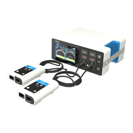
Introduction The EkoSonic™ Endovascular System consists of the EkoSonic™ Device and EKOS™ Control System 4.0. The EKOS™ Control System 4.0 consists of the EKOS™ Control Unit 4.0 (Control Unit), Connector Interface Cable and power cord (see Figure 1). EKOS™ Control Unit 4.0... -
Page 6: Ekosonic™ Device
Control System. All EkoSonic™ Devices will function as intended whether connected to a PT-3B Control System or Control System 4.0. EKOS™ Control System 4.0 The Control System 4.0 includes a portable Control Unit and reusable Connector Interface Cables. The Control Unit has two ports or channels for Connector Interface Cable connections. -
Page 7: Intended Use
Overview operators should receive in-service training from an authorized EKOS™ trainer before operating this equipment. Intended Use The Control Unit is intended exclusively for use with EKOS™ Devices. Contraindications See the EkoSonic™ Device Instructions for Use to get detailed information on contraindications for EKOS Devices. -
Page 8: Front View
Overview Component Description Infusion Catheter: Connects to the Connector Interface Cable. The Infusion Catheter is a multi-lumen catheter that delivers physician specified fluids into the vasculature. Note: This is sometimes referred to as the Intelligent ™ Drug Delivery Catheter (IDDC). Ultrasonic Core: Connects to the Connector Interface Cable. - Page 9 Overview Control/ Description Indictor/ Connector Power Button: Turns the Control Unit ON and OFF. When the Control Unit is ON, a green LED illuminates. Press and hold the button for 3 seconds to turn the Control Unit OFF. Audio Pause Button: Silences the audio alert tone for 5 minutes when pressed.
-
Page 10: Back View
Description Indictor/ Connector battery does not start charging, a battery error may have occurred, call EKOS Help Line. Ultrasound Channel: The Control Unit has two ports or channels for Connector Interface Cable connections. The channels are labeled A and B and can provide energy for up to two devices at the same time. -
Page 11: Side View
For connecting the AC power cord to the Control Unit. Mounting Bracket: Secures Control Unit to infusion stand or custom EKOS™ CU 4.0 Cart. USB Port: Used by qualified personnel to download data and event logs using only a USB memory stick. -
Page 12: Screen Layout - Prior To Connection
Information Tab: Displays Control Unit model number and software version, Connector Interface Cable and device information and the EKOS help line phone number. Graph Tab: Displays a line graph that shows the percentage of the maximum average power delivered for each channel. -
Page 13: Screen Layout - During Ultrasound Therapy
Overview Item Description Displays a configuration menu for setting alert tone volume, screen brightness and language. AC Power / Battery Status Indicator: Provides AC power and battery charge information when the Control Unit is turned ON. Disable Button: Disables channel when “X” icon is pressed. Disable button may be green, yellow or red. - Page 14 Overview Menu Tabs AC Power / Battery Status Channel A Channel B Message Area Message Area Figure 6. Example Screen – During Ultrasound Therapy Item Description Channel Identifier: Indicates channel A or channel B. Note: Messages and information associated with Channel A are provided in the message area on the left side of the display;...
-
Page 15: Color Coding Glossary
Overview Color Coding Glossary Messages and icons are displayed to inform the operator of the state of the Control Unit and device(s). The following color coding is used to help communicate the importance of these messages and icons. Color Description Example GREEN Used to indicate the channel is... -
Page 16: Safety Information
Safety Information Safety Information Warnings and Precautions The following warning and precaution statements provide important information for safe operation of the Control Unit. Observe all warnings and precautions provided in these Instructions for Use. Failure to do so may result in patient injury, operator injury or product damage. - Page 17 WARNING! The Control Unit should be placed on a flat table or attached to the EKOS™ CU 4.0 Cart or an infusion stand during use. If attached to an...
- Page 18 Safety Information infusion stand adhere to following guidelines (see Attaching the Control Unit to an Infusion Stand Section): • Always use an infusion stand that meets the specifications in these Instructions for Use. • Follow the mounting instructions described in these Instructions for Use to ensure the Control Unit is securely attached to the infusion stand.
- Page 19 Angiography Lab and in-patient hospital wards. Control Unit operators should have knowledge of endovascular therapy. All Control Unit operators should receive in‐service training from an authorized EKOS™ trainer before operating this equipment. Caution Carefully read all instructions and precautionary information prior to use.
- Page 20 Safety Information Caution When using two EkoSonic™ Devices (one in channel A and one in channel B), care should be taken to ensure that desired actions (e.g., start ultrasound, stop ultrasound, connect cables, disconnect cables, respond to an alert message) are performed on the correct channel(s) or device(s).
-
Page 21: Power
Power from other devices, similar actions to increase the separation and isolation between the pieces of equipment should be attempted. This equipment also complies with requirements for safe operation when subjected to adverse power line conditions. If this occurs, solution delivery will continue and the operator will be presented with an error message on the display. -
Page 22: Ac Power / Battery Status Indicator
Power • A fully charged battery provides power for approximately 2 hours if one channel is providing therapy or 1 hour if two channels are providing therapy. • Connect the Control Unit to AC power after each use to recharge the battery. Typically, a fully depleted battery will recharge to full capacity in approximately 4 hours. -
Page 23: Battery Gauge
Power Figure 7. Screen with AC Power/Battery Status Battery Gauge When the Control Unit is turned ON and is powered by the battery, a battery gauge shows the level of battery charge. As battery charge decreases, the battery gauge shows the decrease in battery charge. The battery gauge with a red bar indicates a very low or fully depleted battery. -
Page 24: Low Battery Notification
Power Low Battery Notification If the Control Unit is operating on battery power and the battery charge level is 15% or less, a low battery message with an alert icon displays and an audible alert sounds. The percentage of remaining charge and the battery gauge with a red bar in the upper right corner of the display indicates the level of battery charge. -
Page 25: Critically Low Battery
Power Battery Power / Battery Gauge Figure 8. Low Battery Message Critically Low Battery If the Control Unit is operating on battery power and the battery charge level is 5% or less, the critically low battery message with an alert icon displays and an audible alert sounds. -
Page 26: Battery Error
X indicates the battery is defective. Even with a battery error, the Control Unit can continue to operate as long as it is connected to AC power. Do not attempt to open the Control Unit and change the battery. Contact your EKOS representative for information on replacing the battery. -
Page 27: Battery Charging Indicator - Control Unit Turned Off
Power Figure 10. Battery Error Message Battery Charging Indicator – Control Unit Turned Off When the Control Unit is turned OFF, a battery icon is illuminated on the front of the Control Unit to indicate the battery charging status. (see Figure 11). Charging Indicator Figure 11. - Page 28 Power Control Unit Turned Off & AC Connected Indicator Description Steady green indicates Control Unit is connected to AC power and battery is fully charged. Steady yellow indicates Control Unit is connected to AC power and battery is charging. Blinking red (once per second) indicates Control Unit is connected to AC power and has a battery error.
-
Page 29: Ultrasound Operation
Cable. If the device cables are crossed, ultrasound is not operational and could result in delay of ultrasound therapy. Preparing for Ultrasound Use Verify the Control Unit is securely attached to the recommended infusion stand, EKOS™ CU 4.0 Cart, or placed on a table near the patient. - Page 30 EMI from other sources. Press the Power button on the front of the Control Unit. The EKOS boot screen followed by the logo screen display while the Control Unit performs its initial hardware and software test (see Figure 12 and Figure 13).
-
Page 31: Starting Ultrasound
Ultrasound Operation Figure 13. Logo Screen (Starting) Starting Ultrasound The sterile, disposable EkoSonic™ Device is sold separately. Carefully read the Instructions for Use that is provided with the device for a complete description, instructions, warnings, cautions and specifications specific to the EkoSonic™ Device. The Instructions for Use packaged with the EkoSonic™... - Page 32 Ultrasound Operation Figure 14. Activate Screen Pressing the Activate button for either channel displays a connect message indicating to plug the Connector Interface Cable into the Control Unit (see Figure 15). Figure 15. Connect Interface Cable Screen Note: If the Connector Interface Cable is already connected when the Control Unit is turned ON, the channel is automatically activated and a connect device cables message is displayed (see Figure 17).
- Page 33 Ultrasound Operation Connect the Connector Interface Cable to the channel A or B receptacles on the front panel of the Control Unit by inserting the Connector Interface Cable until a click is heard. Note: The Connector Interface Cable can be used in either channel A or B. If providing ultrasound therapy to two devices, connect one Connector Interface Cable to each receptacle (see Figure 16).
- Page 34 Ultrasound Operation Figure 17. Connect Device Cables Screen Connect the Ultrasonic Core to the Connector Interface Cable (see Figure 18). Connect the Infusion Catheter to the Connector Interface Cable (see Figure 18). Ultrasonic Core Infusion Catheter Figure 18. Connect Device Cables Diagram If the device is not properly connected, a connect message displays indicating the specific device cable that needs to be connected (Infusion Catheter or the Ultrasonic Core) (see Figure 19 and Figure 20).
- Page 35 Ultrasound Operation Figure 19. Connect Infusion Catheter Figure 20. Connect Ultrasonic Core Screen Screen Once the device is properly connected, a ready message displays indicating the Control Unit is ready (see Figure 21). Figure 21. Ready Screen Turn on the drug and coolant pumps, and set the specified flow rate per the physician’s orders and within the flow rates specified in the EkoSonic™...
-
Page 36: Monitoring Ultrasound
Ultrasound Operation Press the Start button on the Control Unit for the appropriate channel, when prompted (see Figure 22). WARNING! Never transmit output power (ultrasound therapy ON) from the Control Unit to the EkoSonic™ Device unless it is placed within the patient anatomy, solution is running through the drug lumen, and coolant is flowing through the coolant lumen. - Page 37 Ultrasound Operation When ultrasound is running, a runtime clock counts up, white bands animate in the channel message area and a green Running indication displays. The running status is displayed independently for each channel or device (see Figure 23 and Figure 24). Figure 23.
-
Page 38: Completing Ultrasound
Ultrasound Operation Device. The control unit monitors the device temperature and optimizes the output power to the treatment area. To stop or pause the ultrasound, press the Stop button on the Control Unit for the appropriate channel. When the Stop button is pressed, the ready to start instruction is displayed indicating the total elapsed runtime for the ultrasound therapy (see Figure 26). - Page 39 Ultrasound Operation Figure 27. Ready Screen Showing Disable Button Press the Disable icon on the confirmation screen and the channel becomes inactive (see Figure 28 and Figure 29). Figure 28. Disable Confirmation Figure 29. Disabled/Ready to Screen Activate Screen Disconnect the Infusion Catheter and Ultrasonic Core from the Connector Interface Cable.
-
Page 40: Using An Infusion Stand Or Ekos™ Cu 4.0 Cart
During use or storage, the Control Unit can be attached to the custom designed EKOS™ CU 4.0 Cart or an infusion stand that meets at least the minimum specifications. Alternatively, the Control Unit can be placed on a flat table or cart. -
Page 41: Selecting The Appropriate Infusion Stand
WARNING! The Control Unit should be placed on a flat table or attached to the EKOS™ CU 4.0 Cart or an infusion stand during use. If attached to an infusion stand adhere to following guidelines: • Always use an infusion stand that meets the specifications in these Instructions for Use. - Page 42 Using an Infusion Stand or EKOS™ CU 4.0 Cart • The infusion pumps and Control Unit are positioned as low as practical on the pole. • Access to the infusion pumps is not blocked when the Control Unit is attached.
-
Page 43: Transporting The Patient And Control Unit
EkoSonic™ Device from dislodging. Secure the power cord. Use the carrying handle, the EKOS™ CU 4.0 Cart or an infusion stand to transport the Control Unit with the patient. • Ensure the Control Unit is securely attached to the EKOS™ CU 4.0 Cart or stand. -
Page 44: Maintaining The Control Unit
• Take care not to trip on the power cord or Connector Interface Cable. When the transport is complete, place the Control Unit on a table near the patient. If using the EKOS™ CU 4.0 Cart or an infusion stand, ensure the Control Unit is securely attached. -
Page 45: Storing The Control Unit
Note: For more information about storage and operating specifications see Specifications Section. Place Control Unit on a flat surface or attached to an EKOS™ custom stand, or infusion stand, close to a wall outlet. To maintain a fully charged battery, always connect the Control Unit to a hospital-grade outlet when not in use. -
Page 46: Disposal
Please observe all national and local regulations. In accordance with WEEE requirements, before disposing of the Control Unit or the Connector Interface Cable, contact EKOS Corporation for recovery and recycling instructions. System Information This section describes how to view information for the Control Unit, the Connector Interface Cable and the EkoSonic™... -
Page 47: Power Graph
Power Graph Item Description Control Unit Serial number for Control Unit Software Version Version number for Software Indication of Channel A or B CIC Serial # Serial number for the Connector Interface Cable Ultrasound Serial # Serial number for the Ultrasonic Core Catheter Serial # Serial number for the Infusion Catheter Ultrasound Zone... -
Page 48: Screen Layout - Power Graph
Power Graph Figure 35. Power Graph Menu Tab The power graph displays the power information for each channel with a 6, 12 or 24 hour time scale. As runtime increases the power graph will automatically update to the most appropriate time scale. The percentage of the maximum average power is plotted in the graph. -
Page 49: Example Power Graphs
Power Graph Item Description Green icon indicates ultrasound is ready to start or currently • running. • Yellow icon indicates further steps are required to start the ultrasound. Red icon indicates there is an error detected and ultrasound • is not running. •... -
Page 50: Snapshot
Power Graph The next power graph screen (Figure 38) shows an example of what is displayed for two channels when one device is replaced during therapy. For example, one device is connected to channel A and one device is connected to channel B. Ultrasound therapy was running for approximately 15.5 hours continuously for both devices, then the device connected to channel B was replaced with a new device. -
Page 51: System Configurations
System Configurations Figure 39. Example - Snapshot Power Graph System Configurations This section describes how to select audible alert tone volume, screen brightness and language on the Control Unit. Caution When using the Control Unit, care should be taken to optimize the display brightness and volume level for the use environment. -
Page 52: Audible Alert Volume
System Configurations Audible Alert Volume To increase the volume, tap the right volume symbol until the desired volume is achieved. To lower the volume, tap the left volume symbol until the desired volume is achieved. Note: The minimum setting reduces the volume but does not silence the tone. Screen Brightness To increase the brightness, tap the right circle until the desired brightness... -
Page 53: Troubleshooting
If the issue cannot be resolved by following the onscreen instructions, note the error code in parentheses at the end of the message and contact your local EKOS representative or call +1.425.415.3100. Note: In the event that the Control Unit is not operational and ultrasound therapy has stopped, infusion of the solutions will not be interrupted. - Page 54 Message Error Possible Cause Troubleshooting Step Description Code Unrecoverable E007 System failure. Contact your local EKOS Control Unit error. representative or call +1.425.415.3100 Critically low battery. E003 Control Unit is not Connect the Control Unit to AC connected to AC power.
-
Page 55: Channel Errors
If the issue cannot be resolved by following the onscreen instructions, note the error code in parentheses at the end of the message and contact your local EKOS representative or call +1.425.415.3100. - Page 56 4. Reconnect the Infusion Catheter and ensure the connection is secure. 5. Resume ultrasound. Please contact E301 Channel error. Contact your local EKOS EKOS Help Line. representative or call E303 +1.425.415.3100. E316 E317 E318 E319...
- Page 57 Cable connection to disconnected from Control Unit. the Control Unit. the Control Unit while ultrasound is running. Replace the E307 Defective Replace Connector Interface Cable, Connector Interface Connector E315 Cable. Interface Cable. E321 Contact your local EKOS representative or call +1.425.415.3100.
-
Page 58: Channel Messages
Infusion Catheter and Ultrasonic the Infusion Core. Catheter, Ultrasonic Core, or both. The same error has Control Unit has Contact your local EKOS occurred three detected the same representative or call times. error three times in +1.425.415.3100. a row. -
Page 59: Symbols And Indicators
Symbols and Indicators Figure 48. Channel A and B Messages Figure 47. Channel A Message Descriptions of some of the channel messages are: • Press Start to begin ultrasound. • Plug the interface cable into the control unit. • Plug the device connectors into the interface cable. •... - Page 60 Symbols and Indicators Symbol Description Audio Pause Button: Silences the audio alert tone for 5 minutes when pressed. Pressing the button when audio is silenced turns on the audio alert tone. Steady green indicates Control Unit is connected to AC power and battery is fully charged.
- Page 61 Symbol Description Information Tab: Displays Control Unit model number and software version, Connector Interface Cable and device information and the EKOS help line phone number. Graph Tab: Displays a line graph that shows the percentage of the maximum average power delivered for each channel.
- Page 62 Symbols and Indicators Symbol Description Defective battery. Contact your local EKOS representative or call +1.425.415.3100. Disables channel when pressed. Disable button may be green, yellow or red. Displays the current runtime for the channel. Runtime is the length of time a device has delivered ultrasound therapy on a channel. Time is displayed in Hours:Minutes:Seconds.
- Page 63 The USB port is for use only by, or at the instruction of, authorized EKOS personnel for downloading procedure log files or uploading new software. When connecting to this port all personnel should first touch the metal housing of the Control Unit chassis with their hand to minimize any potential ESD before plugging in the USB device.
- Page 64 Symbols and Indicators Symbol Description European Directive 2012/19/EU regarding Waste Electrical and Electronic Equipment (WEEE) applies to this device. Canadian Standards Association Certification for the United States. Equipotential Terminal The terminal marked with this symbol is the equipotential terminal. It can be connected to a locally available external equipotential line to prevent danger caused by the difference in the potentials between this device and the other devices.
- Page 65 Symbols and Indicators...
-
Page 66: Specifications
Specifications Specifications System Specifications Models EKOS™ EkoSonic™ Endovascular System consisting of: (A) EKOS™ Control Unit (Model 4.0) (1) Power cord (2) Connector Interface Cable (B) EkoSonic™ Device (2) Classification Complies with ISO 60601-1, Edition 3. Complies with ISO 60601-1-2 Class A Emissions Limits when used with the provided medical grade power cord, two Connector Interface Cables (700-10410), and two EkoSonic™... - Page 67 Ordering Information: Product Catalog Number EKOS™ Control Unit model 4.0 600-40500 Connector Interface Cable 700-10410 Power Cord Power cord part numbers vary by geography. For the part number for power cord for your geography please contact your local EKOS representative.
-
Page 68: Electromagnetic Emissions Declarations
Specifications Electromagnetic Emissions Declarations Guidance and manufacturer’s declaration – electromagnetic emissions The Control Unit is intended for use in the electromagnetic environment specified below. The customer or the user of the Control Unit should assure that it is used in such an environment. Emissions text Compliance Electromagnetic environment - guidance... - Page 69 Specifications Guidance and manufacturer’s declaration – electromagnetic immunity The Control Unit is intended for use in the electromagnetic environment specified below. The customer or the user of the Control Unit should assure that it is used in such an environment. IMMUNITY test IEC 60601 test Compliance level...
- Page 70 Specifications Guidance and manufacturer’s declaration – electromagnetic immunity The Control Unit is intended for use in the electromagnetic environment specified below. The customer or the user of the Control Unit should assure that it is used in such an environment. IMMUNITY test IEC 60601 test Compliance level...
- Page 71 Specifications Recommended separation distances between portable and mobile RF communication equipment and the Control Unit The Control Unit is intended for use in an electromagnetic environment in which radiated RF disturbances are controlled. The customer or the user of the Control Unit can help prevent electromagnetic interference by maintaining a minimum distance between portable and mobile RF communications equipment (transmitters) and the Control Unit as recommended below, according to the maximum output power of the communications equipment.
Need help?
Do you have a question about the EKOS and is the answer not in the manual?
Questions and answers