Table of Contents
Advertisement
Quick Links
Advertisement
Table of Contents

Summary of Contents for TRADEDX SSR-4N108L
- Page 1 JBOD SSR-4N108L User Manual...
- Page 2 This product is in conformity with the protection requirements of EU Council Directive 2014/30/EU on the approximation of the laws of the Member States relating to electromagnetic compatibility. TradeDX cannot accept responsibility for any failure to satisfy the protection requirements resulting from a non-recommended modification of the product.
- Page 3 Safety Information Read this important safety information section. Retain this manual for reference. Read this section before servicing. CAUTION: To reduce the risk of electric shock, this JBOD should only be serviced by qualified service personnel. RTC Battery CAUTION: Danger of explosion if battery is incorrectly replaced. Replace only with same or equivalent type recommended by the manufacturer.
- Page 4 Further Safety Information Be sure to read all caution and danger statements in this documentation before performing the instructions. Read any additional safety information that comes with your JBOD or optional de- vice before you install the device. Safety Precautions For your protection, observe the following safety precautions when setting up your equipment: ...
- Page 5 The equipment has been dropped or damaged. The equipment has obvious signs of damage. DO NOT LEAVE THIS EQUIPMENT IN AN ENVIRONMENT WHERE TEMPERATURES EX- CEED 60 °C (140 °F); IT MAY DAMAGE THE EQUIPMENT. Symbols The following symbols will appear in this manual to indicate different safety precaution: Hazardous voltages are present.
- Page 6 CAUTION: When replacing the lithium battery, use only Foxconn Part Number XXXXX or an equivalent type battery rec- ommended by The manufacture. If your system has a module containing a lithium battery, replace it only with the same module type made by the same manufacturer. The battery contains lithium and can explode if not properly used, handled, or disposed of.
- Page 7 CAUTION: The following label indicates a hot surface. CAUTION: The power control button on the device and the power switch on the power supply do not turn off the electrical current supplied to the device. The device also might have more than one power cord. To remove all electrical current from the device, ensure that all power cords are disconnected from the power source.
- Page 8 CAUTION: Do not place any object on top of rack-mounted devices. Attention: This JBOD is suitable for use on an IT power distribution system whose maximum phase-to-phase voltage is 240 V under any distribution fault condition. CAUTION: Hazardous moving parts are nearby.
-
Page 9: Table Of Contents
Table of Contents Introduction ..............................13 Checklist ..............................13 System Tour ............................13 Front View ............................... 14 Rear View ..............................15 Rear Panel Board ..........................15 System Architecture ..........................16 System Operations ............................17 Powering on ............................17 Powering down ............................17 Set Storage Configuration ........................ - Page 10 Installing a Rear Top Cover ......................... 34 Removing a Front Top Cover....................... 35 Installing a Front Top Cover ........................ 36 Storage ..............................37 Installing a 3.5'' HDD ........................... 37 Removing a 3.5'' HDD .......................... 39 Expander Board ............................40 Removing an Expander Board ......................40 Installing an Expander Board ......................
- Page 11 Installing an Inner Rail ......................... 51 Rail Bracket ............................. 52 Removing a Rail Bracket ........................52 Installing a Rail Bracket ........................53 HDD Backplane ............................54 Removing a HDD Backplane ........................ 54 Installing a HDD Backplane ......................... 55 Connectors ..............................57 Expander Boards .............................
- Page 12 Updating Expander Board Firmware....................... 74 Updating Expander Board Firmware Using Linux ................... 75 Checking Expander Version Using Linux ....................80 Specification ..............................84 Before You Contact TradeDX ........................84 Contact ................................ 85...
-
Page 13: Introduction
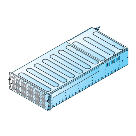
Introduction The SSR-4N108L features 4U JBOD with 108 HDD trays. Checklist Carefully unpack the SSR-4N108L box and check that the following items were included. SSR-4N108L 2 x External miniSAS HD cable 2 x Power cord (optional) ... -
Page 14: Front View
Item Item HDD carrier x 108 Expander board carrier x 2 Power distribution board (PDB) 4 1600W power supply unit x 2 Rear panel board Fan module x 12 4U JBOD chassis HDD drawer Cable chain Chassis Management Module (CMM) Cable cover PDB cover Fan board... -
Page 15: Rear View
Rear View Item Item Fan Module x 12 Rear Panel Board 1600W Power Supply x 2 Rear Panel Board Item Item External management RJ45 x 1 Debug connector (USB type B) External miniSAS HD connector x 4 UID button Power button with LED UID and system status LED... -
Page 16: System Architecture
System Architecture... -
Page 17: System Operations
System Operations This section provides information about getting your JBOD up and running Powering on Follow these steps to turn on the system: Connect the power cord to the power socket at the rear of the JBOD and plug the other end into a power outlet. Press the power button once to turn on the JBOD. - Page 18 Execute the ipmitool command to reset all installed expanders after topology mode changed. Command: #ipmitool –H <ip address> -U <username> -P <password> -I lanplus raw 0x30 0x02 <Expander ID> 0x00 Hint: <Expander ID>: ID of specified expander, must be 1 ~ 4. Example : Set JBOD topology mode as “0x01: Standard”.
-
Page 19: Get Jbod Topology Configuration
Set JBOD topology mode as “0x04: Shared”. #ipmitool –H 192.168.0.100 -U admin -P admin -I lanplus raw 0x30 0x04 0x01 0xa0 0x04 #ipmitool –H 192.168.0.100 -U admin -P admin -I lanplus raw 0x30 0x04 0x02 0xa0 0x04 #ipmitool –H 192.168.0.100 -U admin -P admin -I lanplus raw 0x30 0x04 0x03 0xa0 0x04 #ipmitool –H 192.168.0.100 -U admin -P admin -I lanplus raw 0x30 0x04 0x04 0xa0 0x04... - Page 20 b. JBOD topology mode is “0x04: Shared” currently. #ipmitool –H 192.168.0.100 -U admin -P admin -I lanplus raw 0x30 0x03 0x01 01 a0 04 #ipmitool –H 192.168.0.100 -U admin -P admin -I lanplus raw 0x30 0x03 0x02 02 a0 04 #ipmitool –H 192.168.0.100 -U admin -P admin -I lanplus raw 0x30 0x03 0x03 03 a0 04 #ipmitool –H 192.168.0.100 -U admin -P admin -I lanplus raw 0x30 0x03 0x04...
-
Page 21: Hardware Installation
Hardware Installation Introduction The procedures in this section apply to the SSR-4N108L JBOD model Safety Measures Computer components and electronic circuit boards can be damaged by discharges of static electricity. Working on computers that are still connected to a power supply can be extremely dangerous. -
Page 22: Power Supply Units (Psu)
Power supply Units (PSU) Removing a Power Supply Unit Follow these steps to remove the power supply unit: Hold a PSU handle and press the release latch to unlock from the chassis. Pull a PSU out of the chassis. Installing a Power Supply Unit Follow these steps to install the power supply unit: Align a PSU with the chassis bay. -
Page 23: System Fans
System Fans Removing a System Fan Follow these steps to remove a system fan: Press the latch to release a fan module. Slide to remove a fan module. Repeat the previous steps for the remaining fans. Installing a System Fan Follow these steps to install a system fan: Align a fan module with chassis bay. -
Page 24: Hdd Drawer
HDD Drawer Opening a HDD Drawer Follow these steps to open an HDD drawer: Remove the screws securing an HDD drawer and the chassis. Note: The screws are only for shipping. Loosen the thumb screws securing an HDD drawer. Slide an HDD drawer out of the chassis. Closing a HDD Drawer Follow these steps to close an HDD drawer: Slide an HDD drawer in place. -
Page 25: Removing A Hdd Drawer
Removing a HDD Drawer Follow these steps to remove an HDD drawer: Power off the JBOD and detach all of the power cords from the power supply. Open an HDD drawer. See “Opening an HDD Drawer” on page 13. Remove a cable cover. See “Removing a Cable Cover” on page 35. Remove the HDDs. -
Page 26: Installing A Hdd Drawer
Pull out the HDD drawer from the chassis. Installing a HDD Drawer Follow these steps to install an HDD drawer: Install a cable chain. See “Installing a Cable Chain Module” on page 38. Pull out the middle rail and make sure ball bearing retainer is locked. Align an HDD drawer with the middle rails. - Page 27 Connect the cables to the HDD backplanes. Align the rear cable chain bracket with the HDD drawer. Slide a rear cable chain bracket to lock on the HDD drawer. Make sure a rear cable chain bracket is locked on the HDD drawer. Secure a rear cable chain bracket to the HDD drawer with a screw.
-
Page 28: Removing A Hdd Drawer In Limited Space
Removing a HDD Drawer in limited space Follow these steps to remove an HDD drawer in limited space: Power off the JBOD and detach all of the power cords from the power supply. Open an HDD drawer. See “Opening an HDD Drawer” on page 13. Remove a cable cover. - Page 29 Press the release latches to unlock an HDD drawer and slide an HDD drawer into the chassis. Slide an HDD drawer into the chassis until a click sound.
- Page 30 Pull out an HDD drawer to luck position and press the release latches to unlock. Pull out an HDD drawer.
-
Page 31: Installing A Hdd Drawer In Limited Space
Installing a HDD Drawer in limited space Follow these steps to install an HDD drawer in limited space: Make sure the ball bearing retainer is fixed at the front of middle rail. Align an HDD drawer with the middle rails. Connect the cables to the HDD backplanes. - Page 32 Slide in an HDD drawer until it is locked. Push the mechanism at the front of inner rail to OFF. Press the release latches and slide until the HDD drawer has been inserted into the chassis.
-
Page 33: Top Cover
Top Cover Removing a Rear Top Cover Follow these steps to remove a rear top cover: Open an HDD drawer. See “Opening an HDD Drawer” on page 13. Remove a cable cover. See “Removing a Cable Cover” on page 35. Remove an HDD drawer. -
Page 34: Installing A Rear Top Cover
Installing a Rear Top Cover Follow these steps to install a rear top cover: Install a cable chain. See “Installing a Cable Chain Module” on page 38. Install a front top cover. See “Installing a Front Top Cover” on page 27. Align the tabs on a rear top cover with the slots on the front top cover. -
Page 35: Removing A Front Top Cover
Removing a Front Top Cover Follow these steps to remove a front top cover: Power off the JBOD and detach all of the power cords from the power supply. Open an HDD drawer. See “Opening an HDD Drawer” on page 13. Remove a cable cover. -
Page 36: Installing A Front Top Cover
Installing a Front Top Cover Follow these steps to install a front top cover: Install a cable chain. See “Installing a Cable Chain Module” on page 38. Align a front top cover over the chassis. Slide a front top cover as shown in the following illustration. Make sure the top cover is flush with the front of the chassis, and secure with screws. -
Page 37: Storage
Storage Installing a 3.5'' HDD Follow these steps to install a 3.5” HDD: Open an HDD drawer. See “Opening an HDD Drawer” on page 13. Press and slide the release button. The handle pops up. Lift up the handle to open. Remove an HDD assembly from the chassis. - Page 38 Align the marks on an HDD with the pins on the HDD carrier. Close the latch to secure an HDD. Align an HDD assembly with the connector on the HDD backplane. Install an HDD assembly. Gently press down on both ends of an HDD assembly to ensure it is seated in the HDD backplane.
-
Page 39: Removing A 3.5'' Hdd
Removing a 3.5'' HDD Follow these steps to remove a 3.5” HDD: Open an HDD drawer. See “Opening an HDD Drawer” on page 13. Press and slide the release button. The handle pops up. Lift up the handle to open. Remove an HDD assermbly from the chassis. -
Page 40: Expander Board
Expander Board Removing an Expander Board Follow these steps to remove an expander board: Open an HDD drawer. See “Opening an HDD Drawer” on page 13. Press and slide the release button. The handle pops up. Lift up the handle to open. Remove an expander board assembly from the chassis. -
Page 41: Installing An Expander Board
Installing an Expander Board Follow these steps to install an expander board: Align the holes on an expander board with the standoffs on the expander board carrier. Secure an expander board to the expander board carrier with screws. Align an expander board assembly with the connector on the HDD backplane. Install an expander board assembly. -
Page 42: Cable Cover
Cable Cover Removing a Cable Cover Follow these steps to remove a cable cover: Power off the JBOD and detach all of the power cords from the power supply. Open an HDD drawer. See “Opening an HDD Drawer” on page 13. Remove the screws securing a cable cover to the HDD drawer. -
Page 43: Cable Chain Module
Cable Chain Module Removing a Cable Chain Module Follow these steps to remove a cable chain module: Power off the JBOD and detach all of the power cords from the power supply. Open an HDD drawer. See “Opening an HDD Drawer” on page 13. Remove a cable cover. -
Page 44: Rear Panel Board (Rpb)
Install the top covers. See “Installing a Front Top Cover” on page 27 and “Installing a Rear Top Cover” on page 25. Install an HDD drawer. See “Installing an HDD Drawer” on page 17. Install a cable cover. See “Installing a Cable Cover” on page 36. Close an HDD drawer. -
Page 45: Installing Rear Panel Board
Installing Rear Panel Board Follow these steps to install a RPB: Align the I/O ports on a RPB with the slots on the chassis. Slide a RPB into position. Make sure the I/O ports are seated correctly. Lower a RPB onto the chassis. Make sure the screw holes on a RPB and chassis are aligned. -
Page 46: Installing A Fan Board
Installing a Fan Board Follow these steps to install a fan board: Align the holes on a fan board with the holes on the chassis. Lower a fan board onto the chassis. Make sure a fan board is locked on the chassis. Secure a fan board to the chassis with screws. -
Page 47: Power Distribution Board Cover (Pdb Cover)
Power Distribution Board Cover (PDB Cover) Removing a Power Distribution Board Cover Follow these steps to remove a PDB cover: Power off the JBOD and detach all of the power cords from the power supply. Open an HDD drawer. See “Opening an HDD Drawer” on page 13. Remove a rear top cover. -
Page 48: Power Distribution Board (Pdb)
Power Distribution Board (PDB) Removing a Power Distribution Board Follow these steps to remove a PDB: Power off the JBOD and detach all of the power cords from the power supply. Open an HDD drawer. See “Opening an HDD Drawer” on page 13. Remove a rear top cover. -
Page 49: Chassis Management Module (Cmm)
Connect the cables to a PDB. Install a PDB cover. See “Installing a Power Distribution Board Cover (PDB Cover)” on page 44. Install a rear top cover. See “Installing a Rear Top Cover” on page 25. Close an HDD drawer. See “Closing an HDD Drawer” on page 14. Chassis Management Module (CMM) Removing a Chassis Management Module Follow these steps to remove a CMM:... -
Page 50: Inner Rail
Inner Rail Removing an Inner Rail Follow these steps to remove an inner rail: Power off the JBOD and detach all of the power cords from the power supply. Open an HDD drawer. See “Opening an HDD Drawer” on page 13. Remove the HDDs. -
Page 51: Installing An Inner Rail
Installing an Inner Rail Follow these steps to install an inner rail: Align the keyholes on an inner rail with the standoffs on the HDD drawer. Slide an inner rail backward so that the standoffs lock in place. Secure an inner rail to the HDD drawer with screws. Repeat the previous procedures for the additional inner rail. -
Page 52: Rail Bracket
Rail Bracket Removing a Rail Bracket Follow these steps to remove a rail bracket: Power off the JBOD and detach all of the power cords from the power supply. Open an HDD drawer. See “Opening an HDD Drawer” on page 13. Remove the HDDs. -
Page 53: Installing A Rail Bracket
Installing a Rail Bracket Follow these steps to install a rail bracket: Align the holes on a rail bracket with the pins on an HDD drawer. Secure a rail bracket to an HDD drawer with screws. Install the inner rail. See “Installing an Inner Rail” on page 49. Turn an HDD drawer over. -
Page 54: Hdd Backplane
HDD Backplane Removing a HDD Backplane Follow these steps to remove an HDD backplane: Power off the JBOD and detach all of the power cords from the power supply. Open an HDD drawer. See “Opening an HDD Drawer” on page 13. Remove the HDDs. -
Page 55: Installing A Hdd Backplane
Repeat the previous procedures for the additional HDD backplane. Installing a HDD Backplane Follow these steps to install an HDD backplane: Align the holes on an HDD backplane with the pins on an HDD drawer. - Page 56 Align the holes on a strength panel with the holes on an HDD drawer. Secure a strength panel to an HDD drawer with screws. Repeat the previous procedures for the additional HDD backplane. Connect a FFC cable to the HDD backplanes. Install a rail bracket.
-
Page 57: Connectors
Connectors Expander Boards Item Item XCede high speed connector to HDD Expander chipset backplane Expander chipset heat sink Expander board fault LED Fan Board Item Item 2 x 6-pin power connector to PDB 1 x 7-pin fan connector to fan x 12 2 x 10-pin signal connector to PDB... -
Page 58: Power Distribution Board
Power Distribution Board Item Item PSU connector x 2 2 x 6-pin power connector to fan board 2 x 9-pin signal connector to HDD back- 2 x 10-pin signal connector to fan board plane 1 2 x 8-pin signal connector to HDD back- 2 x 6-pin signal connector to RPB plane 2 2 x 10-pin power connector to HDD... -
Page 59: Hdd Backplane 2
HDD Backplane 2 Item Item 2 x 9-pin signal connector to PDB 2 x 10-pin power connector to PDB MiniSAS HD connector to RPB HDD connector x 53 1 x 40-pin FFC connector to HDD back- XCede connector to expander board plane 1 1 x 40-pin FFC connector to HDD back- HDD connector x 55... -
Page 60: Chassis Managemnt Module (Cmm)
Chassis Managemnt Module (CMM) Item Item PCIe x4 gold finger to HDD backplane 1 BMC chipset Cabling Power Cable Routing... -
Page 61: Signal Cable Routing
Signal Cable Routing... -
Page 62: Rackmount Installation
Rackmount Installation Removing a Chssis from the Rack CAUTION: This procedure requires at least two operators to hold and install the chassis. Follow these steps to remove a chassis from the rack: Power off the JBOD and detach all of the power cords from the power supply. Open an HDD drawer. -
Page 63: Installing A Chassis On The Rack
Installing a Chassis on the Rack CAUTION: This procedure requires at least two operators to hold and install the chassis. Follow these steps to install a chassis on the rack: Before you begin, make sure the rails are rails are properly installed on the chassis and the rack. -
Page 64: Removing The Rackmount Rails
Removing the Rackmount Rails Follow these steps to remove the rackmount rails: Remove a chassis from the rack. See “Removing a Chassis from the Rack” on page 63. Remove the screws securing the rear support brackets and the rack. Remove the screws securing the rails to the rack. Remove the rails from the rack. -
Page 65: Installing The Rackmount Rails
Hold the bar nut to prevent it from dropping and remove the securing screw. The bar nut is now free to remove. Installing the Rackmount Rails Follow these steps to install the rackmount rails: Align the bar nut on the flange of the rail. The shape is designed to allow the bar nut to sit flush with the flange. - Page 66 First place the front side of the rails flush with the rail post. Secure the front side of the rails and the rack with screws. Extend the rear of the rail until the rear of the rail is flush with the rear side of the rear rack post.
- Page 67 Align the support bracket with the rear post. Make sure the holes on the support bracket are aligned with the bar nut, now located behind the post. Secure the rear support brackets in the rack with screws. Repeat for the remaining rail.
-
Page 68: Configuration
Configuration Chassis Management Module (CMM) IP Address The CMM FW can be configured using Static or DHCP IP address settings. Set the IP address by using the system management software --default setting is DHCP. Username and Password A username and password are required to establish a session. The user should also have ac- cess to the same LAN subnet. - Page 69 CMM Image File Naming File naming information: SHM<Major><Minor><SKU>.ima SHM: Identifiers for specified product. <Major>: Two characters for major version number. <Minor>: Two characters for minor version number. <SKU>: Single character for SKU identifier, typical “A”, “B”, …. Example: SHM0101A.ima: Image file for FW version 1.01.
- Page 70 Example: Specified Image-1 (active) to be flashed. [root@localhost]# ./Yafuflash -nw -ip 10.67.222.129 -u admin -p admin -mse 1 SH- M0100A.ima INFO: Yafu INI Configuration File not found... Default options will not be ap- plied... Creating IPMI session via network with address 10.67.222.129...Done ------------------------------------------------- YAFUFlash - Firmware Upgrade Utility (Version 4.89.0) -------------------------------------------------...
- Page 71 Flashing [conf] Module ..Flashing Firmware Image : 100%... done Verifying Firmware Image : 100%... done Flashing [bkupconf] Module ..Flashing Firmware Image : 100%... done Verifying Firmware Image : 100%... done Flashing [root] Module ..Flashing Firmware Image : 100%... done Verifying Firmware Image : 100%...
- Page 72 Specified Image-2 (inactive) to be flashed. [root@localhost]# ./Yafuflash -nw -ip 10.67.222.129 -u admin -p admin -mse 2 SH- M0100A.ima INFO: Yafu INI Configuration File not found... Default options will not be applied... Creating IPMI session via network with address 10.67.222.129...Done ------------------------------------------------- YAFUFlash - Firmware Upgrade Utility (Version 4.89.0) -------------------------------------------------...
-
Page 73: Checking The Cmm Fw Version Using Linux
Checking the CMM FW Version Using Linux Log into the Linux terminal. Open the terminal. Execute the ipmitool command to display the FW version as shown in the following figure. Command: #ipmitool –H <ip address> -U <username> -P <password> -I lanplus mc info Example: [root@localhost]# ipmitool -H 10.67.222.129 -U admin -P admin -I lanplus mc info Device ID... -
Page 74: List All Sensors And Status Using Linux
List All Sensors and Status Using Linux Log into the Linux terminal. Open the terminal. Execute the ipmitool command to display all supported sensors as shown in the following figure. Command: #ipmitool –H <ip address> -U <username> -P <password> -I lanplus sensor Storage Drive LEDs The system LED is used to show the state of the enclosure. -
Page 75: Updating Expander Board Firmware Using Linux
Updating Expander Board Firmware Using Linux To update expander board firmware using Linux: Log into the Linux terminal. Open the terminal. Create a temporary folder /expander Copy the g3Xflash utility and expander FW/MFG images to the /expander folder. Execute the following command to scan the expander device and obtain four expander SAS addresses: ./g3Xflash -i get avail [root@expander]# ./g3Xflash -i get avail... - Page 76 [root@expander]# ./g3Xflash -i 51C666DFB6CB803F down fw Expander-Firmware_Image_ v0.0.0.2_20170223.fw 1 -y ******************************************************************************** g3Xflash Expander Flash Utility Version: 14.1.0.0 Copyright 2016 Avago Technologies. All rights reserved. **************************************************************************Initializing Interface. Expander: SledgeHammer_0 (SAS_35X_36) Expander Validation: Passed Checksum: Passed Target Firmware Region: 01 Current Version: 00.00.00.01 Replacement Version: 00.00.00.02 Image Validation: Passed Pre-Validation of image is successful.
- Page 77 g3Xflash Expander Flash Utility Version: 14.1.0.0 Copyright 2016 Avago Technologies. All rights reserved. ******************************************************************************** Initializing Interface. Expander: SledgeHammer_3 (SAS_35X_36) Expander Validation: Passed Checksum: Passed Target Firmware Region: 01 Current Version: 00.00.00.01 Replacement Version: 00.00.00.02 Image Validation: Passed Pre-Validation of image is successful. Downloading File...
- Page 78 Initializing Interface. Expander: SledgeHammer_0 (SAS_35X_36) Image Validation: Passed Checksum: Passed Current Version: 00.01 Replacement Version: 00.02 Pre-Validation of image is successful. Downloading File... Download Complete. Post-validating..Post-Validation of image is successful. Download Successful. [root@expander]# ./g3Xflash -i 51C666DFB6CB903F down mfg Expander-MFG_Image_ v0.0.0.2_20170223.bin 3 -y ******************************************************************************** g3Xflash Expander Flash Utility...
- Page 79 Pre-Validation of image is successful. Downloading File... Download Complete. Post-validating..Post-Validation of image is successful. Download Successful. Execute the following command to reset whole Expanders: ./g3Xflash –i <SAS Address> re- set exp –y [root@expander]# ./g3Xflash -i 51C666DFB6CB203F reset exp -y ******************************************************************************** g3Xflash Expander Flash Utility Version: 14.1.0.0...
-
Page 80: Checking Expander Version Using Linux
******************************************************************************** g3Xflash Expander Flash Utility Version: 14.1.0.0 Copyright 2016 Avago Technologies. All rights reserved. ******************************************************************************** Initializing Interface. Expander: SledgeHammer_3 (SAS_35X_36) Expander reset request successfully sent to expander. Note: Please add -w parameter for non-disruptive firmware update to avoid SAS I/O interrupt. ... - Page 81 Execute the following commands to get runtime/active firmware versions of whole. Expanders by SAS address: ./g3Xflash –i <SAS Address> get ver [root@expander]# ./g3Xflash -i 51C666DFB6CB203F get ver ******************************************************************************** g3Xflash Expander Flash Utility Version: 14.1.0.0 Copyright 2016 Avago Technologies. All rights reserved. ******************************************************************************** Initializing Interface.
- Page 82 Execute the following commands to get manufacture configuration image versions of whole Expanders by SAS address: ./g3Xflash –i <SAS Address> get ver 3 [root@expander]# ./g3Xflash -i 51C666DFB6CB203F get ver 3 ******************************************************************************** g3Xflash Expander Flash Utility Version: 14.1.0.0 Copyright 2016 Avago Technologies. All rights reserved. ******************************************************************************** Initializing Interface.
- Page 83 Initializing Interface. Expander: SledgeHammer_2 (SAS_35X_36) Reading the MFG Version Info page..Product Id : 48 Platform Id : 00 FW Version : 00.00.00.02 MFG Version : 00.02 Platform Version : 00.00 Product Name :FOXCONN JBOD Platform Name : SledgeHammer_EXP1 [root@expander]# ./g3Xflash -i 51C666DFB6CB203F get ver 3 ******************************************************************************** g3Xflash Expander Flash Utility...
-
Page 84: Specification
Non- operating Temperature -40° C to 70° C Non-operating Relative Humidity 40° C/ 93% RH Before You Contact TradeDX Be sure to have the following information available before you call TradeDX: Technical support registration number (if applicable) Product serial number ... -
Page 85: Contact
Contact Address: TradeDX s.r.o. Karlov 245 284 01, Kutná Hora Czech Republic To contact TradeDX by a phone, call 00420737264041 For other contact information, please visit website: www.tradedx.eu/contacts...
Need help?
Do you have a question about the SSR-4N108L and is the answer not in the manual?
Questions and answers