Advertisement
Table of Contents
WIRING
===================================================================================
Warning: TO AVOID PERSONAL INJURY, DO NOT USE THIS SWITCH ON MACHINERY WITH AN
1.
UNGUARDED POINT OF OPERATION.
READ WARNING STATEMENT on reverse side of this page.
2. When wiring up this device make sure POWER IS OFF AND LINES ARE DEAD.
3. MAXIMUM FUSE RATING: Amperage and voltage not to exceed nameplate rating – Quick Acting.
4. Supply cord with flexible conductors (leads) to be prepared as shown. (See Diagram "A").
Supply cord with prepared flexible conductors. Use special purpose crimping tools to apply female quick connect and when required, ring
terminals to conductors.
NOTE: For metal Aquiline models, the cord must include a 4-1/2 in. (114mm) long green or for CE Marked foot switches, a green / yellow
colored grounding conductor. Apply a #8 (4.4mm ø) ring type terminal. Attach to and tighten the protective earthing (grounding terminal with
lockwasher) screw 11-16 in.-lbs. (1.2 to 1.8 Nm).
NOTE: For CE Marked foot switches, a cord guard or bend relief must be provided that extends beyond the cord clamp at least five times the
overall diameter of the flexible cord.
2-1/8 in (53.9 mm)
3/16 IN x 0.031 or x 0.020
(4.8 x 0.8 or x 0.5 MM)
Female quick-connect terminal.
See switch for thickness
of Male terminal.
5. Remove cover from base by prying the cover with a flat blade screwdriver on the side shown in Diagram "B".
NOTE: For metal Aquiline models, remove hinge screws.
6. Loosen or remove cord clamp screws, insert cord and connect inner conductors (leads) of cord to appropriate switch terminals.
(See Diagram "C"). NOTE: For metal Aquiline models, remove plastic insulation from switch before connecting cord leads to terminals.
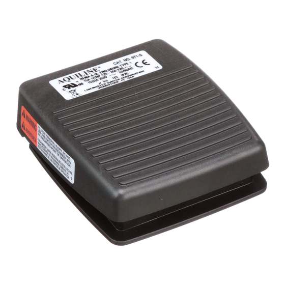
971-S (SPDT)
7. The circuit designations shown in Diagram "C" are at assembly. For 974-S only, the left side interior switch is reverse actuated in the foot
switch housing. For example, the normally closed terminal (NC) marking molded into the switch body will provide a normally open circuit when
the interior switch is assembled in the foot switch housing.
8. Re- assemble cover to base by snapping onto hinge tabs as shown in Diagram "D".
NOTE: For metal Aquiline models; replace plastic insulation on switch then reassemble cover with hinge screws.
9. CLEANLINESS must be observed during installation and in use.
on a REGULAR BASIS, inspect foot switch frequently to guard against wear, damage, unlawful alterations or removal of guards, or for
unusual enclosure deterioration and the like. Inspect the entire length of the connecting cord (or wiring system) from where it enters the foot
switch to the equipment it's wired up to for wear, loose strain relief connections and the like. DO NOT OPERATE the foot switch if any of the
above is observed or if the nameplate or warning label has been obscured or removed.
It is IMPERATIVE that inspection authorities and users exercise more than ordinary care with regard to installation and maintenance and that
this information be made available to the end user, operators, maintenance personnel and to others responsible for the proper installation and
safe operation of this foot switch.
ADDITIONAL COPIES of this information sheet and warning labels are available upon request
MOUNTING
================================================================================
1. Aquiline foot operated switches are furnished with a non-skid base pad and can be mounted with the base pad attached.
2. Use 2 number 4 thread-cutting (self-tapping) screws and two number 4 lock washers when mounting foot switch to full guard.
(See Diagram "E") For metal Aquiline models, remove 2 number 4 baseplate screws and use for mounting along with two number 4
lock washer. Also, place two number 6 lock washer, furnished with guard, between the bottom of the metal Aquiline baseplate inside of guard
and check for continuity between the foot switch enclosure grounding lead and guard.
AQUILINE Foot Operated Switch
3/8 IN (9.5
DIAGRAM "A"
Cord clamp accepts cord,
DIAGRAM "C"
sizes .250 to .435 diameter.
(6 to 11 mm).
Tighten cord clamp screws
Alternately 12 to 14 IN-LBS.
2 nd Stage
(1,4 to 1,5 Nm).
3/16 IN. x 0.031 or x 0.020
(4,8 x 0,8 or 0,5 mm)
flat quick-connect tabs
for switch terminations.
972-S (2 STAGE)
#522-B14 Full guard with
assem bly hardware and
instructions available upon
request.
#4 Lockwasher
mm) Min.
Base
Cord Clamp
Use 2 conductor cord for single pole
normally open or normally closed
operation. Use 3 conductor cord for
single pole double throw operation.
Maximum flexible conductor size: #14
2
AWG. (1.5 mm
).
This interior switch only has
1 st Stage
Solder type terminations
See note 6
974-S (DPDT)
Note:
For twin models use #522-B12 full guard.
#4 Flat head thread-cutting screw
DIAGRAM "E"
Make sure cover is pried off
of base from this side only.
DIAGRAM "B"
DIAGRAM "D"
IMPORTANT!
Make sure that the
hinge hole in the cover is located
over this hinge tab pins prior to
snapping the cover onto the base.
.
Form 997-J Rev L
Advertisement
Table of Contents

Summary of Contents for Linemaster AQUILINE 971-S
- Page 1 AQUILINE Foot Operated Switch WIRING =================================================================================== WARNING: TO AVOID PERSONAL INJURY, DO NOT USE THIS SWITCH ON MACHINERY WITH AN UNGUARDED POINT OF OPERATION. READ WARNING STATEMENT on reverse side of this page. 2. When wiring up this device make sure POWER IS OFF AND LINES ARE DEAD. 3.
- Page 2 LINEMASTER personnel to be experts on standards and requirements for all these products. We offer over 150 stock foot switch models and guards plus a large variety of specials, which are made to customer specifications.
- Page 3 09/21/99 Created revision page, changed size of paper from 8.5”x11” to 6.5”x10”. (ECN 004346) (JAB) 05-18-00 Revised Note #2 on mounting and added www.linemaster.com phone number. (PER ECN #006563) (JMB) 12-17-01 Added note to mounting section of instruction sheet. (CSR...
Need help?
Do you have a question about the AQUILINE 971-S and is the answer not in the manual?
Questions and answers