Advertisement
®
LCD EWP
(SUITABLE FOR USE WITH ALL DAVIES, CRAIG EWP
PLEASE READ ALL THESE INSTRUCTIONS THOROUGHLY BEFORE YOU START WORK.
DON'T RUSH - ENSURE YOU HAVE FULL UNDERSTANDING OF THE WORK AHEAD BEFORE YOU
COMMENCE. ENSURE YOU HAVE ALL TOOLS AND COMPONENTS REQUIRED.
Congratulations on your purchase of the Davies, Craig EWP
Controller
(PATENTS: USA 6425353, EU 1133624, AUS 756453)
manage the operation of your chosen EWP
your pump in response to coolant temperature and it will manage the on/off
control of your Thermatic
The Controller will run the EWP
heat and avoid heat-soak.
The Controller has a push-button control to allow you to choose one of
nine set operating temperatures.
Generally, higher engine temperatures will offer improved fuel
efficiency and lower temperatures will increase power.
It's recommended that engine operational temperatures be checked
against those nominated by your vehicle manufacturer.
KIT CONTENTS:
Item
Description
No.
EWP Digital Controller
1.
Assembly
Wiring Harness
2.
(Includes 10Amp Fuse)
3.
Sensor Assembly
4.
In-Line Adaptor
5.
Hose Clamps
6.
Ring Terminal
7.
Rubber Sleeves
Not
Velcro
Shown
Not
Installation Instructions
Shown
LCD EWP/Fan Digital Controller Customer Instructions – Part #18922 (July17)
/FAN DIGITAL CONTROLLER INSTRUCTIONS
(ELECTRIC BOOSTER PUMP), AND THERMATIC
®
Fan.
Qty
1
1
1
1
2
1
2
2
1
Phone: +61(0)3 9369 1234
Fax:
info@daviescraig.com.au
www.daviescraig.com.au
®
s (ELECTRIC WATER PUMP), EBP
®
®
or EBP
®
after ignition shutdown to dissipate
Figure 1: LCD EWP/Fan Digital Controller Kit
Components.
77 Taras Avenue
P.O. Box 363
Altona North
Vic 3025 Australia
+61(0)3 9369 3456
®
FANS)
®
/Fan Digital
. This Controller will
by varying the speed of
Page 1 of 12
®
s
Advertisement
Table of Contents

Related Manuals for Davies Craig LCD EWP/FAN DIGITAL


Summary of Contents for Davies Craig LCD EWP/FAN DIGITAL
- Page 1 (Includes 10Amp Fuse) Sensor Assembly In-Line Adaptor Hose Clamps Ring Terminal Rubber Sleeves Velcro Shown Figure 1: LCD EWP/Fan Digital Controller Kit Installation Instructions Components. Shown LCD EWP/Fan Digital Controller Customer Instructions – Part #18922 (July17) Page 1 of 12...
- Page 2 ® INSTALLING THE LCD EWP /FAN DIGITAL CONTROLLER 1. The Controller should be installed inside the passenger compartment to minimise its ambient temperature and exposures to water as the unit is not waterproof. Also minimise exposure to direct sunlight. Locate a hole in the firewall (approx. 20mm in diameter) and pass the wiring harness (including the sensor &...
- Page 3 Figure 2: Digital Controller Wiring Diagram OPERATION OF DIGITAL CONTROLLER CONTROLLER ALGORITHM-PUMP OPERATION The ‘set point’ can be programmed to any setting between 40°C (104°F) to 110°C (230°F). Digital Controller Operation Chart. Page 3 of 12...
-
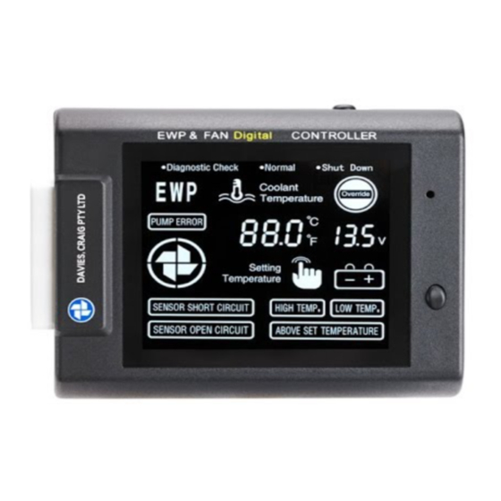
Page 4: Diagnostic Check
OPERATION of LCD THEMPERATURE INDICATOR Rises with increased engine temperature EWP SYMBOL ® = EWP operating in ‘pulsing’ mode – Refer Digital Controller Operations FLASHING Curve, areas & ® ON = Electric Water Pump (EWP ) working at full speed. FAN SYMBOL Circulating = fan operating DIAGNOSTIC CHECK System warning has been triggered. -
Page 5: Voltage Display
• When the cooling system is cold, remove top radiator hose and confirm that the inside diameter of your top radiator hose is between 30 to 42 mm prior to cutting hose. If the hose is more than 42mm, call Davies Craig and await 6mm sleeves. Page 5 of 12... - Page 6 • If the parts supplied (adaptor and/or sleeves) are suitable, select an appropriate location in a straight section of the hose then cut the radiator hose. • Temporarily slide radiator hose clamps on each end of the hose. Fit both cut ends of hose onto the In-line Adaptor (with or without sleeves as appropriate).
- Page 7 4. Once the tapping process is completed, apply a couple of layers of PTFE sealant tape (not supplied) to the thread on the brass body, then screw it into the thermostat housing Figure 4: Sensor Installation in to Thermostat Diagram ®...
- Page 8 FAN ONLY OPERATION The Davies, Craig LCD EWP/Fan Digital Controller is programmed to earth the electric fan relay at 3°C above the set point. The Controller will continue to operate the fan until the coolant temperature is below the set point.
- Page 9 ® THERMATIC FAN WIRING TO THE DIGITAL CONTROLLER Please follow the instructions 1&2 below if you are using the Davies Craig Universal Fan Fitting Kit (Parts #1000, 12V; #1001, 24V). 1. Cut the ring terminal off the black wire (85) from the Fan wiring loom to a sufficient length, this wire (with relay) to be joined with the black/green wire from the Digital Controller.
-
Page 10: Troubleshooting
CONTROLLER DIAGNOSTIC CHART Condition Troubleshooting Blown fuse • Controller does not operate / No display Check all the wire connections • Controller receiving low voltage < • 10.5V 12V voltage indicator flashing Controller receiving high voltage > • 17.5V Controller receiving low voltage < •... -
Page 11: Installation Recommendations
INSTALLATION RECOMMENDATIONS • For improved heater performance on vehicles which have the heater inlet (return) and outlet ports in the mechanical pump housing, Davies Craig has available an Electric Booster Pump Kit, EBP 15 #9001 (12V) or EBP23 #9050 (12V) or EBP40 #9040 (12V). - Page 12 Page 12 of 12...
Need help?
Do you have a question about the LCD EWP/FAN DIGITAL and is the answer not in the manual?
Questions and answers
Just installed new EWP (150) and digital controller (8001). Checked and rechecked all wiring: but screen only flashes on and off. Pump did start and stop but that is all. Unit receiving 12.1 volts Alarm sounding intermittently. No other indicators. Bought some time ago but this is first install .
The Davies Craig LCD EWP/FAN DIGITAL controller flashing on and off after installation could be caused by the following issues:
1. Blown Fuse: Check and replace the fuse if necessary.
2. Low Voltage: Ensure the controller is receiving sufficient voltage. For a 12V system, it should not be receiving less than 10.5V, and for a 24V system, it should not be receiving less than 21.5V.
3. High Voltage: Ensure the controller is not receiving excessive voltage. For a 12V system, it should not exceed 17.5V.
4. Wiring Connections: Inspect all wire connections to ensure they are secure and correctly installed.
This answer is automatically generated