Table of Contents
Advertisement
Quick Links
Advertisement
Table of Contents

Summary of Contents for Actia IHMI
- Page 1 IHMI v2 USER’S MANUAL DOC 02110 revision 1 ACTIA PCs...
- Page 2 All or part of this documentation cannot be duplicated or translated by any mean, without written authorization from the ACTIA PCs company. This documentation is delivered as is. Liability of the ACTIA PCs company cannot be involved in case of damage resulting from its practice.
-
Page 3: Table Of Contents
CAN............................. 37 CompactFlash preparation tools ..................37 ELECTRICAL SPECIFICATIONS....................39 MAINTENANCE..........................47 Battery replacement ......................47 APPENDICES..........................48 Mechanical drawings......................48 Product label ........................50 INCIDENT REPORT SHEET......................51 NOTES ............................52 DOC 02110-1 ACTIA PCs Page 3 / 52... -
Page 4: Description
This basic system can be equipped with extensions (WiFi, Bluetooth etc.). A dedicated location is provided to receive a GSM (GPRS/EDGE/2G/3G) optional module. Optionally, an external Mixing Panel PDB (DOC08024) can also be used with the IHMI v2 in order to add remote interfaces such as serial com ports, automotive inputs/outputs, CAN Bus, audio Line out/microphone, etc…... -
Page 5: Warning
The recycling of matrials will help to conserve natural resources. For more detailed information about recycling of this product, please contact your local Civic Office or your household waste disposal service. DOC 02110-1 ACTIA PCs Page 5 / 52... -
Page 6: Features
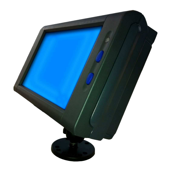
FEATURES The IHMI v2 is composed with two different boards: The MPC-BayTrail processor board and a IHMI-MPC baseboard. The main features are: 7” Wide LVD Display 800x480 / Backlight Led with luminosity key control and ambient light sensor Restive touch screen (4 wires) Intel BayTrail processor board (extended temperature -40 / +85°... -
Page 7: Connectors
CONNECTORS Main connectors outputs are located on the IHMI v2 left panel under a cable cover. In order to access them, it is necessary to remove the back plastic cover, if present, and the cable metal cover. To remove the back plastic cover, remove the 4 red arrow marked screws in holes using a Torx 10 screwdriver. -
Page 8: Connectors Location
Before unplugging the cables, you must cut the cable ties. Connectors location Ethernet 10/100/1000 Base T Mixing Panel Jumpers Internal Speaker Left Internal Speaker Right Internal Microphone Antenna cables DOC 02110-1 ACTIA PCs Page 8 / 52... -
Page 9: Ethernet
This connector offers a USB interface in addition to the interfaces located on the board. Designation Function 1, 3, 5, 9, 10 GNDUSB2 Electrical ground (shield, case) USB2- Signal data USB- USB2+ Signal data USB- GNDUSB2 Electrical ground 7, 8 VUSB2 USB power supply (max 1A) DOC 02110-1 ACTIA PCs Page 9 / 52... -
Page 10: Mixing Panel
To detect a positive voltage, the board is equipped with a zone for jumper E26 and E27 (see CONFIGURATION chapter). VCC (Internal +5V) Vehicle signal input Switch To internal logic 400V diode 470pF 100nF 4.7K DOC 02110-1 ACTIA PCs Page 10 / 52... -
Page 11: Antennas
A Blue FAKRA connector (C code) is used for the GPS receiver. A Bordeaux-Violet FAKRA connector (D code) is used for the GSM. WIFI A Green FAKRA connector (E code) is used for the Wifi. DOC 02110-1 ACTIA PCs Page 11 / 52... -
Page 12: Configuration
Low level => signal activation by connection to battery + High level => signal activation by connection to battery ground No 120 ohm terminator on Interface CAN 120 ohm terminator on Interface CAN DOC 02110-1 ACTIA PCs Page 12 / 52... -
Page 13: Bios Setup
NOTE: CMOS and E2PROM memories are updated on SETUP exit only if the “Save and Exit” option is selected. Standard Setup +----------------------------------+ ¦Date: 04/22/2015 (mm/dd/ccyy) ¦ ¦Time: 09:32:52 (hh:mm:ss) ¦ +----------------------------------+ DOC 02110-1 ACTIA PCs Page 13 / 52... - Page 14 ¦ First boot device : None ¦ ¦ Second boot device : None ¦ ¦ Third boot device : None ¦ ¦ Fourth boot device : None ¦ ¦ [Esc] key : Removable devices¦ +------------------------------+ DOC 02110-1 ACTIA PCs Page 14 / 52...
- Page 15 This command is used to exit SETUP without modifying the content of the CMOS RAM. Save and Exit This command is used to exit SETUP, saving the modifications in the CMOS RAM. DOC 02110-1 ACTIA PCs Page 15 / 52...
-
Page 16: Compact Flash And Sim Card
Access door on the right panel The access door is maintained by 2 screws (tightening of 0.6Nm). Use a Torx 8 screwdriver to remove it. 2 x M2.5x6 Torx screws (countersunk head) With access door mounted DOC 02110-1 ACTIA PCs Page 16 / 52... -
Page 17: Usb Interface
The SIM card holder is accessed behind the access door on the right panel. To eject the SIM card holder, press the yellow button on the right side of the connector. Reminder: The system must be powered down when loading or unloading the SIM card. DOC 02110-1 ACTIA PCs Page 17 / 52... -
Page 18: Leds
When pressing the reset button with a thin rod through this hole, the power management microcontroller is restarted. The first effect is to turn off the MPC-BayTrail board. - Do not introduce a thin rod in a LED hole. It will damage the LED. DOC 02110-1 ACTIA PCs Page 18 / 52... -
Page 19: Installation
4 hours with relax profile) after the ignition was switched off, power down is forced to preserve battery life. If IHMI v2 cables are not fully installed, the antenna cables, the mixing panel and Ethernet cables and the cable cover must be set following the next 3 paragraphs. -
Page 20: Antenna Cables
Antenna cables The GPS, GSM and WiFi antenna cables must be attached to the IHMI v2 housing. They are maintained by a bridge and a screw (tightening of 0.6Nm). The unsheathed portion of the antenna cables must be located under the bridge. -
Page 21: Mixing Panel And Ethernet Cables
If an USB cable is also required, it must be installed the same way. First install the mixing panel cable: Cable tie Mixing panel cable Unsheathed zone Bracket Then install the Ethernet cable: Unsheathed zone Cable tie Bracket DOC 02110-1 ACTIA PCs Page 21 / 52... -
Page 22: Cable Cover
The cable cover must be positioned in such a way that the cables are not pinched by the metal. It is maintained by 2 screws (tightening of 0.6Nm). 2 x M2.5x6 Torx screws (countersunk head) Cable cover DOC 02110-1 ACTIA PCs Page 22 / 52... -
Page 23: Arm Mount
A diamond base with 1” ball, A round base with 1” ball, A double socket arm. The diamond base ball is fixed to the IHMI v2 housing witch 2 M4 NYLSTOP nuts (tightening of 1.2Nm). Round base Double socket arm... -
Page 24: Back Cover
Back Cover The back cover must be installed after the diamond base ball. It is fixed with 4 panhead plastide M3x10 Torx screws (tightening of 0.2Nm). DOC 02110-1 ACTIA PCs Page 24 / 52... -
Page 25: Buttons
System On and Off Normally the system power is controlled by the ignition signal. However, the IHMI v2 can be configured to not automatically start when the ignition goes on. In that case, pressing any button during more than half second, while the ignition signal is on, turns the system on (cf. -
Page 26: Power Management
This information is not guaranteed. For up-to-date specifications refer to the IHMI-MPC user’s manual (DOC02097). The IHMI-MPC board power supply is managed by a Z8 microcontroller. It allows a PC-compatible system to be adapted to the specific environment of a vehicle. -
Page 27: State Display
MPC processor board manager is requested to shut down the system through a notification. The IHMI-MPC board waits for the module to turn itself off or to place itself in standby. The user can force a module power off by pressing simultaneously both backlight control buttons during al least 2 seconds. -
Page 28: Configuration
Too hot system not stopped 2 minutes after the request Power supply not functional Unable to stop the MPC processor Configuration The microcontroller configuration is defined during manufacturing through 4 zero Ohm resistors on the IHMI- MPC board (cf. DOC02097). Action resistor present Resistor... -
Page 29: Programming Interfaces
PROGRAMMING INTERFACES Several programming interfaces are provided for the operating system and the application to access IHMI v2 functions. Those functions are connected to various buses or controllers and are driven through different standard and proprietary programming interfaces. Controller Interface... -
Page 30: Power Management
USB bus. Refer to the documentation of the mixing panel for details. Power Management The IHMI v2 power supply is managed by a Z8 microcontroller as described previously. Some parameters can be modified via the processor SMBus interface. - Page 31 The timer down counting starts as soon as updated. Register 12h: WAKEUP (R) Bit 0: GSM wakeup flag Bit 1: SMBus wakeup flag Bit 2: not used Bit 3: first power on flag Bit 4: timer wakeup flag DOC 02110-1 ACTIA PCs Page 31 / 52...
- Page 32 Bits 7-0: X axis acceleration in 1/10 G (-90 to +90) Register 1Ah: ACCELEROMETER Y AXIS (R) Bits 7-0: Y axis acceleration in 1/10 G (-90 to +90) Register 1Bh: ACCELEROMETER Z AXIS (R) DOC 02110-1 ACTIA PCs Page 32 / 52...
- Page 33 Note : A new data can be written in flash memory only if the current value is 11111111. A data of 11111111 can only be set by erasing the page containing it. DOC 02110-1 ACTIA PCs Page 33 / 52...
-
Page 34: Specific Bios Functions
2 IDE 1 hard disk 3 IDE 2 hard disk 4 SATA 1 hard disk 5 SATA 2 hard disk 6 SATA 3 hard disk 7 SATA 4 hard disk 8 USB storage device 9 CD-ROM DOC 02110-1 ACTIA PCs Page 34 / 52... -
Page 35: Operating Systems
MPC processor boards are compatible with standard operating systems such as Windows XP, Windows XPe, Windows 7 and Linux. As a result, the IHMI-MPC board, combined with an MPC processor board, is able to support any PC standard software as well as customer application running on standard PC. -
Page 36: Inputs/Outputs
“Power options” of the “Configuration panel”. - If the selected action is “Shut down” and the ignition signal is switched off, the IHMI v2 goes to the power down mode (state 1) at the end of the operating system shutdown. In this state, the vehicle battery power can be removed. -
Page 37: Audio
CompactFlash preparation tools The preferred IHMI v2 system disk is a CompactFlash. However it is not easy to install an operating system on it. In addition software development is usually done on a desktop PC. It is why ACTIA PCs has developed a set of tools and procedures to help the customer in this job. - Page 38 Windows 7 or Windows 8 and a CompactFlash card reader (USB), it is possible to prepare or duplicate CompactFlash that boot on an IHMI v2. Those tools and procedures are available on ACTIA PCs website (www.actia-pcs.fr). DOC 02110-1 ACTIA PCs...
-
Page 39: Electrical Specifications
Audio outputs (J14): Minimum RMS voltage at full scale: 1 V Passband on 10 k: 20 Hz to 20 kHz Audio amplifier (J9 and J10): 2x2W @ 4 ohms 2x1W @ 8 ohms DOC 02110-1 ACTIA PCs Page 39 / 52... - Page 40 Electrostatic protection: 15 kV Antenna type: Fakra C code (Blue) passive or active Antenna impedance: 50 ohms Active antenna recommendations: minimum gain 15dB / maximum gain 50dB / 3.3V 50mA Module: u-blox LEA-6R DOC 02110-1 ACTIA PCs Page 40 / 52...
- Page 41 GSM (Optional) Antenna type: Fakra D code (Bordeaux-violet) passive or active Antenna impedance: 50 ohms Module MC75i (EDGE World) 1/2 DOC 02110-1 ACTIA PCs Page 41 / 52...
- Page 42 Module MC75i (EDGE World) 2/2 DOC 02110-1 ACTIA PCs Page 42 / 52...
- Page 43 Module PHS8 (3G World) 1/2 DOC 02110-1 ACTIA PCs Page 43 / 52...
- Page 44 Module PHS8 (3G World) 2/2 WiFi (optional) Antenna type: Fakra D code (Green) Antenna impedance: 50 Ohms DOC 02110-1 ACTIA PCs Page 44 / 52...
- Page 45 Module: SparkLan WPEA-121N DOC 02110-1 ACTIA PCs Page 45 / 52...
- Page 46 RTC Battery Battery type: CR2032 Long life: 39000h (without external power supply) DOC 02110-1 ACTIA PCs Page 46 / 52...
-
Page 47: Maintenance
CAUTION: HOT SURFACE Battery replacement The IHMI v2 includes a battery. This battery could not be accessed easily. Contact ACTIA PCs SAV for more details. In case of replacement, use the same battery type, characteristics and polarity, otherwise a battery explosion can occur. -
Page 48: Appendices
APPENDICES Mechanical drawings IHMI v2 case DOC 02110-1 ACTIA PCs Page 48 / 52... - Page 49 IHMI v2 with back plastic cover Round base ball (dashboard fixing) DOC 02110-1 ACTIA PCs Page 49 / 52...
-
Page 50: Product Label
To identify each system, a sticker is placed on the rear panel of the product. PRFxxxxx-yww-zzz-11 xxxxx = Product code yww = Year + week (ex: 428 = 2014, week 28) zzz = serial number 11 = revision E24 xxR–xxxxxx =E-marking number DOC 02110-1 ACTIA PCs Page 50 / 52... -
Page 51: Incident Report Sheet
INCIDENT REPORT SHEET Before returning the product, it is essential to contact the ACTIA PCs After Sales Service to obtain a return number (RMA) to be written in the box of this document. The information which will be shown on this sheet will be used to determine the cause(s) of the fault or malfunction, thereby helping to improve the quality of our services. -
Page 52: Notes
NOTES DOC 02110-1 ACTIA PCs Page 52 / 52...
Need help?
Do you have a question about the IHMI and is the answer not in the manual?
Questions and answers