
Subscribe to Our Youtube Channel
Summary of Contents for Polytron SPM 2000 LAN
- Page 1 PolyCompact Kopfstelle PolyCompact Headend SPM 2000 LAN Bedienungsanleitung User manual 0901840 V1...
- Page 2 Firmenhandbuch, die ohne Zustimmung des Erstellers erfolgen, können zum Verlust der Ge- währleistung bzw. zur Ablehnung der Produkthaftung seitens des Herstellers führen. Für Verbesse- rungsvorschläge ist der Ersteller dankbar. Ersteller: Polytron-Vertrieb GmbH Postfach 10 02 33 75313 Bad Wildbad Germany...
-
Page 3: Table Of Contents
3.3.1 Programmablauf "Werkseinstellungen" ..........................7 Programmieren von Modulen ............................8 Speichern/Laden der Daten über USB-Stick ........................8 Software update SPM 2000 LAN durch Verwendung eines USB-Sticks ................9 Funktion Telecontrol................................ 10 Beschreibung .................................. 10 Einstelllungen an der Grundeinheit ..........................10 CAT 5-Netzwerkkabel .............................. -
Page 4: Montage- Und Sicherheitshinweise
Deutsch Montage- und Sicherheitshinweise... -
Page 5: Hinweise Zu Sicherheitsanforderungen An Antennenanlagen
Hinweise zu Sicherheitsanforderungen an Antennenanlagen Ihre Antennenanlage muss den Sicherheitsanforderungen nach DIN EN 60728-11 (VDE 0855-1) entsprechen. Bild 1 Verdrahtung der Antennenanlage Bitte beachten: Wegen Brandgefahr durch Blitzeinschlag ist es empfehlenswert, alle metallischen Teile auf einer nicht brennbaren Unterlage zu montieren. Brennbar sind Holzbalken, Holzbretter, Kunststoffe etc. Kopfstation erden Kopfstation über die an der Rückseite angebrachte Erdungsklemme gemäß... -
Page 6: Beschreibung
(Bild 3) dienen zur Anwahl und Bestätigung der Bedienschritte und zum Einstellen der Werte. Nach dem Einschalten (Anschluss ans Stromnetz) der SPM 2000 LAN werden die Daten eingelesen und konfigu- riert. Dieser Vorgang kann bis zu 40 Sekunden dauern. Einschalten... -
Page 7: Programmieren Von Sat-Eingangsfrequenzen
Im Standby-Modus die Taste (rechts) drücken, bis die Anzeige Program/Service erscheint. Nun gemäß nach- folgendem Programmablauf die Werkseinstellung aufrufen. Danach werden die Funktionen der SPM 2000 LAN überprüft und die werkseitigen Grundeinstellungen wiederhergestellt. Diese Prüf- und Einstell-Routine ist abge- schlossen, wenn der Standby-Modus wieder angezeigt wird, auf den das Gerät automatisch zurückspringt. -
Page 8: Programmieren Von Modulen
6) Nach ca. 20 Sekunden geht die Kopfstelle zurück in den Standby-Modus. HINWEIS Digitalmodule müssen danach neu programmiert werden, da nur die Daten in der Grundeinheit aktualisiert werden. Polytron Headend USB-Stick SPM 2000 LAN D.2 einstecken Software-Version Polytron Headend Stand-by-Modus SPM 2000 LAN D.2... -
Page 9: Software Update Spm 2000 Lan Durch Verwendung Eines Usb-Sticks
Software update SPM 2000 LAN durch Verwendung eines USB-Sticks Neue Firmware von der Polytron Homepage www.polytron.de downloaden. Datei SPM2000_XX.UC3 in das Root-Verzeichnis des USB-Stick kopieren. USB-Stick in den USB-Port der SPM 2000 LAN stecken. Das Update-Menü aufrufen (siehe unten). Update bestätigen. -
Page 10: Funktion Telecontrol
Einstellungen an der Grundeinheit Um die Grundeinheit auf die Fernbedienbarkeit vorzubereiten, sind die auf Seite 12 abgebildeten Einstellungen an der Grundeinheit SPM 2000 LAN vorzunehmen. CAT 5-Netzwerkkabel Dem Gerät liegt ein CAT 5-Netzwerkkabel bei. Damit kann das Gerät direkt mit einem Router verbunden werden. -
Page 11: Angelegte Kopfstelle Auswählen
Angelegte Kopfstelle auswählen 1. Gewünschte Kopfstelle mittels Mauszeiger auswählen. 2. Doppelklick auf den Pfeil vor dem Namen oder auf die Schaltfläche „Download“ klicken. Die Übersicht der beste- henden Programmierung wird heruntergeladen. Kanalliste bearbeiten 1. Modulplatz mit dem zu programmierenden Modul anwählen. Hierzu z.B. auf die Schaltfläche „Slot 2“ klicken. 2. -
Page 12: Einstellungen An Der Grundeinheit Spm 2000 Lan
Einstellungen an der Grundeinheit SPM 2000 LAN ◄ : zurück ► : weiter + bestätigen ▼▲ : hoch + runter ► Gedrückt halten bis Anzeige aktiviert ist. Polytron Headend SPM 2000 LAN X.X. Mit ▼▲ den Bereich Service auswählen und mit ► bestätigen ! Program ←... -
Page 13: Maße Und Anschlusszeichnungen Spm 2000 Lan
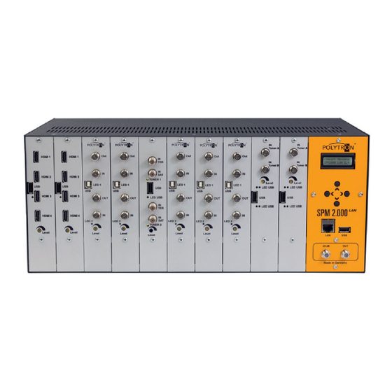
Maße und Anschlusszeichnungen SPM 2000 LAN Bild 4 Bedien- und Anzeigeelemente, Anschlüsse 1 Steckplätze für die Module 3 Ausgang (links außen Steckplatz 1 4 Testausgang (ca. -20 dB) rechts außen Steckplatz 10) 5 USB-Anschluss 2 Display für Programmierung 6 LAN-Anschluss und Anschluss für den CopyKey... -
Page 14: Technische Daten
Technische Daten Ausgang Frequenzbereich ............................47 - 862 MHz Ausgangspegel bei 10 Kanälen ........................100 dBμV Anschlüsse..............................F-Buchsen Impedanz ................................75 Ohm 1 x ................................HF-Ausgang 1 x ..............................Messbuchse -20 dB Stromversorgung Betriebsspannung ........................180 - 265 V~, 50/60 Hz Leistungsaufnahme ............................ -
Page 15: English
The creator is grateful for suggestions for improvement. Creator: Polytron-Vertrieb GmbH Postfach 10 02 33 75313 Bad Wildbad Germany... -
Page 16: Mounting And Safety Instructions
10 Mounting and safety instructions... -
Page 17: Notes On Safety Requirements For Antenna Systems
10.1 Notes on safety requirements for antenna systems Your antenna system must comply with DIN EN 60728-11 (VDE 0855-1). Reflector Aerial Grounding bar ES-06 Figure 6 Wiring of the antenna system Please note: Due to the risk of fires caused by lightning strikes, all metal parts must be mounted on a non-combustible base. Combustible materials include wooden beams and boards, plastic boards etc. -
Page 18: Description
11 Description The PolyCompact headend station SPM 2000 LAN, newly designed of Polytron, is a compact, modular channel pro- cessing device for small and medium-sized communal installations and offers a variety of advantages. These are: compact design, simple operability, LAN port,... -
Page 19: Programming Of Sat Input Frequencies
(right) until the display shows Program/Service. Now call up the factory set- ting according to the following program flow. The functions of the SPM 2000 LAN are checked then and the factory settings will be restored. The routine is completed if the headend jumps back again in the standby mode automati- cally, shown in the display. -
Page 20: Programming Of Modules
4) To load the data from the USB stick select the menu point “Import data“. 5) The display shows “Loading Settings“ respectively “Save Settings”. 6) After approx. 20 seconds the SPM 2000 LAN will return to stand-by mode. NOTE Digital modules must then be reprogrammed because only the data in the base unit is updated. -
Page 21: Software Update Spm 2000 Lan Via Usb Stick
12.6 Software update SPM 2000 LAN via USB stick Download new Firmware from Polytron homepage www.polytron.de. Copy file SPM2000_XX.UC3 to the root directory of the USB stick. Plug the USB stick into the USB port of the SPM 2000 LAN. Open the update menu (see below). Confirm update. -
Page 22: Function Telecontrol
The device can be programmed via the Internet by connection to a router (e.g. a DSL router). 13.2 Settings on the base unit To prepare the base unit for remote control mode, the settings of the base unit SPM 2000 LAN shown on page 24 have to be done. -
Page 23: Choosing Created Headend
15.2 Choosing created headend 1. Select the required headend via mouse pointer. 2. Double click on the arrow in front of the name or click on the “Download“ button. The overview of the existing pro- gramming will be downloaded. 15.3 Modify channel list 1. -
Page 24: Settings On The Base Unit Spm 2000 Lan
16 Settings on the base unit SPM 2000 LAN ◄ : back ► : forward + confirm ▼▲ : up + down (scroll) ► Press and hold until display is enabled. Polytron Headend SPM 2000 LAN X.X. Select Service mode by ▼▲ and confirm with ► ! Program ←... -
Page 25: Dimensions And Connection Drawings Spm 2000 Lan
17 Dimensions and connection drawings SPM 2000 LAN Figure 9 Control- and display elements, connections 1 Module slots 3 Output (left side module slot 1 4 Test output (approx. -20 dB) right side module slot 10) 5 USB port 2 Display for programming... -
Page 26: Montage / Assembly
18 Montage / Assembly 18.1 19“ Montage / Installation in a 19" rack Figure 11 Installation in a 19" rack 18.2 Wandmontage / Wall mounting Figure 12 Wall mounting... -
Page 27: Anlagenbeispiele / Plant Examples
/ QAM) oder über terrestrische Netze (DVB-T / COFDM). In one base unit SPM 2000 LAN up to 6 modules of the type SPM-H4TCT (each module 4 HDMI inputs) can be run. The changeable type of modulation allows the distribution of the output signals via cable (DVB-C / QAM) or terrestri-... -
Page 28: Technical Data
+ 49 (0) 70 81/1702 - 0 Technische Hotline Technical hotline + 49 (0) 70 81/1702 - 0 Telefax + 49 (0) 70 81) 1702 - 50 Internet http://www.polytron.de eMail info@polytron.de Technische Änderungen vorbehalten Subject to change without prior notice Copyright © Polytron-Vertrieb GmbH...
Need help?
Do you have a question about the SPM 2000 LAN and is the answer not in the manual?
Questions and answers