Subscribe to Our Youtube Channel
Summary of Contents for Lectrotab ELECTROMECHANICAL TRIM TAB SYSTEMS
- Page 1 ELECTROMECHANICAL TRIM TAB SYSTEMS Operation and Installation Manual Linear Devices Corporation www.lectrotab.com dba Lectrotab Phone: 804-368-8428 11126 Air Park Road, Suite G Fax: 804-368-8438 Ashland, VA 23005...
-
Page 2: Table Of Contents
Table of Contents • Introduction/Safety…………………………3 • How Do Trim Tabs Work……………….…4 • Tab Plate Installation……………………….5 • Actuator Installation/Wiring…..…..6-7 • Rocker Switch Wiring………………………8 • Oval LED Control Wiring………………….9 • Operation……………………………………...10 • Troubleshooting…………………………….11 • Warranty Information……………………12... -
Page 3: Introduction/Safety
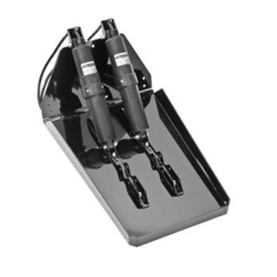
Lectrotab designs and manufactures premium quality electromechanical trim tab systems for the leisure and commercial marine markets. The Lectrotab system is easy to install on new boats or to replace existing trim tabs. All Lectrotab actuators are covered by a worldwide lifetime warranty. -
Page 4: How Do Trim Tabs Work
How Do Trim Tabs Work Boaters will enjoy many performance and efficiency benefits by adding Lectrotab trim tabs. Lectrotab trim tabs improve fuel efficiency, increase boat speed, accelerate shallow water planing, eliminate porpoising, and enhance the overall boating experience with a more comfortable ride. -
Page 5: Tab Plate Installation
Tab Plate Installation • Review Installation: Review the tab plate and actuator installation diagrams in Fig 1 and 2 to ensure there are no interference issues with the tab plates or actuator on the boat transom before actual mounting begins. Place the actuator and tab plate against the transom before mounting to correct any interference problems before mounting begins. -
Page 6: Actuator Installation/Wiring
Actuator Installation • Required Tools: Straight edge, screw driver, drill, 3/16” (5mm) and 11/32” (9mm) drill bits, 7/16” (11mm) deep well socket and wrench, 3M 5200 Sealant, #14X1-1/4” (6X30mm) pan head stainless steel screws • Mount Actuator: 1. Remove plastic bag containing ¼” carriage bolts and nuts from actuator rubber band. 2. - Page 7 KA Kits include actuators with 6’ (1.8m) extended cable and 20’ (6.1m) cable (W4-20) to attach from the actuators to the control switch (see Fig. 4). This cable is also available in longer lengths. Visit www.lectrotab.com for additional cable lengths listed under Products/Individual Parts and Accessories.
-
Page 8: Rocker Switch Wiring
The SAF-SC is a flat rocker switch, and the SAB-S has an extended lever type switch handle. Both switches are for single station applications. For dual station applications, a SAF-NSC or SAB-NS must be used. For detailed control switch specifications, visit www.lectrotab.com under Products or Technical Library/Technical Manuals or Wiring Diagrams. -
Page 9: Oval Led Control Wiring
The Oval control switch has LED indicators to show tab angle. For dual station applications, an SR cable for each Oval must be used. For dual station, dual actuators per tab applications or programming information, visit www.lectrotab.com under Products or Technical Library/Technical Manuals or Wiring Diagrams. -
Page 10: Operation
LED indicator to the opposite side indicating the bow is going down, then please review the Oval or Wireless program chart at www.lectrotab.com under Products/Controls. 2) Press the bottom left “PORT BOW UP” switch until you feel the boat’s port side begin to come up then release the lower left “PORT BOW UP”... -
Page 11: Troubleshooting
"LEDs OFF" state. See Oval "LEDs ON" state. See Oval program chart tab at program chart tab. www.lectrotab.com under Products/Oval. In a dual station system, the Test second station Oval control as in section (1a) described second station Oval control above. -
Page 12: Warranty Information
To determine if a Lectrotab part is covered under warranty, please see the “Warranty Period” listed below. All Lectrotab parts have a serial number date code used to determine if the part is still within the warranty period. The actuator serial number is located on the right side of the upper cover. An example for actuators would be “AK09”...

Need help?
Do you have a question about the ELECTROMECHANICAL TRIM TAB SYSTEMS and is the answer not in the manual?
Questions and answers