Table of Contents
Advertisement
Installation Manual & Set-Up Guide
Ordinary Area
ITAS Ambient Sensing Control Panel
ITAS-EXT Ambient Sensing Extender Control Panel
ITLS Line Sensing Control Panel
ITLS-EXT Line Sensing Extender Control Panel
Hazardous Area
ITASC1D2 Ambient Sensing Control Panel
ITASC1D2-EXT Ambient Sensing Extender Control Panel
ITLS C1D2 Line Sensing Control Panel
ITLS C1D2-EXT Line Sensing Extender Control Panel
PK497-5
0037-75514
June 2018
1
Advertisement
Table of Contents

Subscribe to Our Youtube Channel
Related Manuals for Chromalox IntelliTrace ITAS-EXT

Summary of Contents for Chromalox IntelliTrace ITAS-EXT
- Page 1 Installation Manual & Set-Up Guide Ordinary Area ITAS Ambient Sensing Control Panel ITAS-EXT Ambient Sensing Extender Control Panel ITLS Line Sensing Control Panel ITLS-EXT Line Sensing Extender Control Panel Hazardous Area ITASC1D2 Ambient Sensing Control Panel ITASC1D2-EXT Ambient Sensing Extender Control Panel ITLS C1D2 Line Sensing Control Panel ITLS C1D2-EXT Line Sensing Extender Control Panel PK497-5...
-
Page 2: Safety Precautions
Safety Precautions IMPORTANT SAFEGUARDS Throughout the IntelliTrace Setup Guide, these sym- To avoid electrical shock or injury, always remove pow- ® bols will alert you to potential hazards. Safety precau- er before servicing a circuit. Personnel working with tions should always be followed to reduce the risk of or near high voltages should be familiar with modern fire, electrical shock, injury and even death to persons. -
Page 3: Table Of Contents
Table of Contents Contents Page Number Safety Precautions ..............................ii Table of Contents ..............................iii Introduction ................................1 Model Overview ..............................2 Theory of Operation .............................. 3 Types of Sensing Control ............................. 4 Pre-Service Storage .............................. 5 Before Powering Up ............................. 5 General Panel Notes ............................ -
Page 5: Introduction
Introduction For nearly 100 years, customers have relied upon Chromalox for premiere quality and innovative solutions for industrial heating applications. Chromalox manufactures the world’s largest and broadest line of electric heat and control products. The IntelliTrace ITLS & ITAS Series Multiple Circuit Panels and Extender Panels are a complete temperature ®... -
Page 6: Model Overview
Model Overview The Chromalox line of IntelliTrace Heat Trace Control vide the flexibility for the owner to meet their process ® Panels provides a significant amount of application expansion needs. Simply connect the Extension Panel and feature flexibility. to its matching ITLS, ITLSC1D2 or ITAS, ITASC1D2... -
Page 7: Theory Of Operation
Theory of Operation The set-up of the individual and global circuit parameters is explained in the Temp/Load Set-up sections of this manual. This Theory of Operation overview is intended to give a quick summary of how it all works together. •... -
Page 8: Types Of Sensing Control
Types of Sensing Control Ambient Sensing Control Strict ambient-sensing control utilizes a thermostat or a simple electronic controller which senses the ambient tem- perature via an RTD, Thermocouple or Bulb & Capillary sensor. This is the simplest type of control as the heating circuit is energized only when the ambient temperature drops below the setpoint of the controlling device. -
Page 9: Pre-Service Storage
The internal temperature must be at least 5˚C (9˚F) above the ambient. Before Powering Up Chromalox takes great pride in knowing that we have provided to you a product of premium quality and workman- ship. We have taken every precaution to ensure that your equipment arrives safe and secure. -
Page 10: General Panel Notes
General Panel Notes This panel is designed to UL508A to facilitate NEC and CEC compliance, However it is the responsibility of installer(s) and end user(s) to make sure that the installation wiring and all equipment, including this panel, fulfill appropriate national and local electrical code requirements. Incoming and outgoing branch circuit conductors may not be protected by fuses or breakers in this panel. -
Page 11: Installation
Heat Trace Panels employ an HMI Touch Screen with LED backlit technology. UV Rays are known ® to be damaging to these types of HMI touch screens. Chromalox insists on installing HMI Sunscreens in all outdoor applications to protect the HMI Touch screen from these harmful rays. -
Page 12: Main Menu Screen
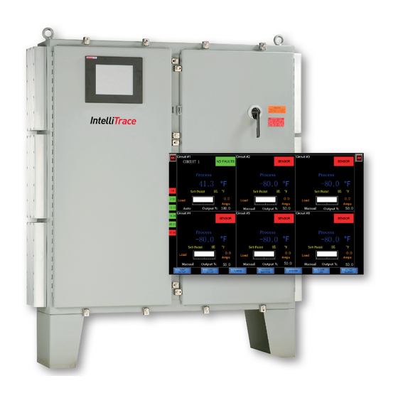
Main Menu Screen The ITAS/ITLS Touch Screen Computer is extremely user friendly and quite intuitive. Navigation to any other screens or any 2 or 6 circuit grouping of circuts is accomplished by selecting the blue labeled buttons along the bottom of the screen or in the upper right or left hand corners. The main menu screen displays alarm status, circuit number, circuit name, process and set point temperatures, current load demand, manual/auto control state and output percentage for 2-6 circuits at a time. -
Page 13: Temp Setup Menu
Temp Setup Menu The Temp Setup button at the bottom of the screen is a quick launch to the Temperature Property Sheet which is simply a series of tabaulated screens. See Figure 2. Figure 2 Each block contains input cells for the panel operation. For example, temperature and overide controls are located within the Temp Setup Screen. -
Page 14: Security Levels & Password Screen
Security Levels & Password Screen After touching the Temp Setup button, but before the Temp Setup Menu is presented, a pop-up screen request- ing a password will appear. See Figure 3: Figure 3 Initial factory set passwords for the below levels of Security are: Level Title Code... -
Page 15: Temp Setup Menu (Cont.)
Temp Setup Menu The Temp Setup Menu tab (See Figure 4) contains input cells for the following settings for each circuit: • Customized Naming of each Circuit • Process Temperature Set Point • High & Low Temperature Alarm Limits • Maximum allowable GFEP (Ground Fault Equipment Protection) Alarm Limit •... - Page 16 Temp Setup Menu Navigation notes: 1. Each screen illustrates 2 or 6 circuits at a time. To make setting changes to circuits beyond the current screen within the Temp Setup Menu, one must select the Circuit Navigation buttons in the upper right or left of screen. Figure 5 illustrates the input cell identification and location for a single circuit within the Temp Setup Menu: Figure 5 Circuit Name...
-
Page 17: Apply Settings Globally
Definitions for each of the Temp Setup Input Cells: Name: Customize the Name of this individual circuit or loop Temp STPT: Process Temperature Set Point (degrees F or C) HI STPT: High Temperature Alarm Limit (degrees F or C) LO STPT: Low Temperature Alarm Limit (degrees F or C) Auto/Manual: Select Auto if you wish the Output behavior to be a function of a PID Algorithm or ON/OFF... -
Page 18: Load Setup Menu
Load Setup Menu The Load Setup Menu (See Figure 6) contains input Additionally, there exists a “Global Setting” within the cells for the following settings for each circuit: circuit# 1 Grid • High & Low Load Alarm Limits • Apply Glob. Setting •... - Page 19 Definitions for each of the Load Setup Menu Input Cells Load HI Stpt ....High Current Alarm Limit (Amps) LoadLO Stpt ....Low Current Alarm Limit (Amps) GFEP: ......Maximum Allowable Leakage Current setpoint (milliamps) Trip (GFEP): ....Enabled: If the GFEP limit is met, the output will be 0%. Disabled: If the GFEP limit is met, the output is unaffected.
-
Page 20: Tuning Menu
Tuning Menu The owner has a choice of how the output is to be operated: Auto, Manual or Off. These selections are made within the Temp Setup Menu. If “Auto”, or Automatic Control Operation is desired, then the tuning of the automatic con- trol is accomplished via the Tuning Menu. -
Page 21: Control Modes: On/Off, Autotune & Pid
Control Modes: ON/OFF, PID & Autotune ON/OFF Autotune • Select ON/OFF if you wish the operation of the heat- • If the Autotune Feature is selected, then the PID pa- ers to be 100% ON when a demand for heat exists rameters will be calculated and entered by the sys- and 0% once the Set Point Temperature of the Pro- tem once the Autotune function has completed its... -
Page 22: Sensor Mapping
Sensor Mapping The ITLS and ITLSC1D2 models provide the owner Multiple Sensor Mapping with customizable sensor mapping. This becomes a A single sensor may be used independently or com- very powerful and desirable feature when the owner bined with other sensors to control more than one cir- needs added flexibility in controlling the circuit outputs cuit. -
Page 23: System Properties
System Properties Several informative items and general settings are Here, one can enter/revise the Facility Name, Date, available within the System Menu. Time, Temperature Units, Auto Cycle Interval and Se- curity Codes. The Manager has access to all security The System tab is only available to the two highest codes while the Engineer has access to only the Engi- owner security levels: Manager and Engineer. -
Page 24: Auto Cycle Feature
Auto Cycle Feature During prolonged down time periods, typically during On a sequential circuit basis, the Autocycle feature pe- the summer months, it advisable to intermittently exer- riodically monitors system performance between 1-999 cise the loops. This exercising of the loops is accom- hours. -
Page 25: Communications
Map Instructions Document A-60682-04. This is an ad- dendum to the PK497 manual. Go to the ITLS or ITAS product pages and search in the Technical Resources Tab at: www.chromalox.com. Figure 11 Communication Settings To display the setting screen, touch (Device/ PLC Settings) from (Peripheral Equipment Set- tings) in offline mode. -
Page 26: Alarm Log
Alarm Log The purpose of Alarm Log is to record every alarm on the list (by date) will be removed from the table. This condition with a date and time stamp. This log may be process repeats indefinitely. Once an alarm has been viewed via the ALARM LOG button at the bottom of the recovered, it can be removed from the list by pushing main screen. -
Page 27: Active Alarms
Active Alarms Clearing Alarms Alarms within any 6-circuit or 2-circuit grouping are in- dicted by RED squares in the left and right panels on Except for a Communications Alarm and a Latched any screen. If the square is GREEN, then no faults exist GFEP Alarm, all other alarms are cleared once the ac- within that 6-circuit grouping. -
Page 28: Alarm Troubleshooting
Alarm Troubleshooting The Alarm Condition, the resultant Output and the Design Behavior for each Alarm type can be found in Table 2 below. Table 2 Alarm Type Condition Output Design Behavior HIGH TEMP Sensed Temp No change Alarm will be cleared automatically when =>... -
Page 29: Extension Panels - Connection & Considerations
Sensor Panel Distribution Module Module Extension Panel or Remote Sensor Panel Considerations Chromalox uses the following vendor and cable item as a viable reference: Environmental influences such as EMI/RFI can compro- mise the communication signal between the Extension Example Vendor: ..........L-com or Remote Sensor Panel and the Main Pane. -
Page 30: Wireless Temperature Sensing
Each wireless circuit has its own transmitter battery life meter. This provides The components of the Chromalox Heat Trace Wireless three levels of remaining battery life so that you may Temperature Sensing system include the IntelliTrace properly plan service before it is needed. - Page 31 The BATTERY fault state on the Faults page will change from Green to either Orange or Red depending on the remaining battery life of the Wireless Transmitter. Wireless Transmitter Chromalox has chosen the Rosemount 248 Wireless Temperature Transmitter. This transmitter is WirelessHART ®...
- Page 32 Wireless Temperature Transmitter There are many design and feature options available on Rosemount 248 Wireless Temperature Transmitter, the Rosemount 248 model. Chromalox has standard- USA Intrinsically Safe and Non-incendive, Aluminum or ized on the following: Polymer Housing, with 1/2-14 NPT Conduit Entry Size, WirelessHART, 2.4 GHz, External Omni-directional An-...
- Page 33 Universal Mounting Bracket The Rosemount 248 Wireless Temperature Transmitter may be ordered with or without a matching Universal Mounting Bracket (see above table). This bracket eases and enables transmitter mounting to either pipe struc- tures or flat structural surfaces. Rosemount 248 Wireless Temperature Transmitter with Universal Mounting Bracket (Shown With Aluminum Housing Model) Structure Mount Pipe Mounting...
- Page 34 Transmitter Power Module (Battery) The transmitter power module must be installed prior to device configuration and device use. It may be removed from the device in between configuration and commissioning. The Polymer housing transmitter utilizes the Green Power Module while the Aluminum housing transmitter uses the Black Power Module.
- Page 35 To simplify co-location installation of the RBF 185M Type pipe mounted heat trace temperature sensor and Rose- mount 248 Wireless transmitter, Chromalox has developed a pipe mounting kit. This kit may be installed in both ordinary and hazardous areas (Class I, Divisions 1 or 2).
- Page 36 Wireless Transmitter Pipe Mounting Kit Detail: Installation Notes: 1. The conduit (customer supplied) from the seal fitting to the sensor must be rated for the environment in which it is being installed. 2. Pipe clamps are required to secure the RBF sensor and Kit Pipe Standoff ( C ) to the piping. 3.
- Page 37 Installation Example – Wireless Transmitter and Universal Mounting Bracket to Pipe Mounted Heat Trace Sensor Rosemount 248 Wireless Transmitter 1/2” NPT port, plugged 1/2” NPT port RBF 185M 3/4” NPT Reducer Heat Trace Sensor (comes with RBF Sensor) Environment approved conduit / connection (not provided) Rosemount 248 Universal...
- Page 38 It is also possible to have a hybrid topology called Star- Chromalox will not be held responsible otherwise. Mesh, in which there is a combination of both Mesh For support, Chromalox provides optional professional and Star topologies such as in Figure C.
- Page 39 Site Installation Guidelines Many factors, such as component positioning, equip- Antenna Positioning ment density, site obstructions, and environmental Signal strength will be improved when the antenna of conditions, will impact wireless communication integ- wireless transmitters and /or gateways is unobstruct- rity.
- Page 40 Below is a representation of a typical industrial wireless sensor network: Commissioning the Wireless Network To most efficiently setup and commission your wire- and guidance. These documents are available in the less network, please refer to the RMT 248 Quick Install technical resources tab within the Heat Trace products Guide 00825-0200-4248, RMT 248 Product Data Sheet / Wireless Temperature Sensing section at www.chro-...
-
Page 41: Panel Specifications
Appendix A Specifications Input - 3-wire RTD, 100 W PT, 0.00385 W/W/˚C, 20 W balanced lead wire, Input Types - Dry Contact Closure (Thermostat) - Snow or Ice Sensor (voltage drop) Number of Sensor Inputs 1 to 252 per Circuit Sensing Configuration 1: Sensed Reading 2 (or more): Min, Max, Average... -
Page 42: Default Settings
Alarms Alarm Types Low & High Temperature, Low & High Current, High GFEP, Sensor Failure, Communications, Wireless Transmitter Battery Alarm Relay 5 Amps, Customer Supplied 2-30 VDC or 12-240 VAC Alarm Contact State Mode Default Normal Operation Closed Alarm Condition Open Power Off Open... - Page 43 HMI / Touchscreen. However, without complete Chromalox-recommended Sunscreens. UV protection, the life of the HMI / Touchscreen See HMI Sunscreen Options. will be compromised. For outdoor installations, Chromalox insists on installing an HMI Sunscreen to fully protect the HMI / Touchscreen from harmful...
- Page 44 HMI Sunscreen Options The HMI Sunscreen provides complete protection The Sunscreen collapses nearly flush with the front from the harmful effects of UV Ray exposure. When of the enclosure when not in use and it may be installed properly, along with the supplied hardware secured shut with a common padlock.
- Page 45 Retrofitting control panels with the HMI Sunscreen is done as follows: 1. Use the mounting template below to establish the drill hole locations. 2. Install the provided gas-tight sealing washers and sealing gasket along with the cap screws and nuts. Field Installation Below is the mounting template for the larger Sunscreen, 0076-15392 for the ITLS/ITAS-6-72 designs:...
- Page 46 Wiring Considerations All standard IntelliTRACE panels will have the same core components. Please see the table and pictures below to understand basic wiring needs. Refer to the wiring diagram(s) supplied with your specific panel for reference. ITAS-EXT, ITASC1D2, ITASC1D2-EXT, Item Function ITAS, ITLS ITLS-EXT...
- Page 47 Power Module (6 Pack) Side/Rear Panel Mounted (2-Pack Not Shown) Heater (Load) – OUT Remote Voltage Distribution – IN Heat Trace or Other Resistive Heater Loads are connected here. Unless an optional Z-Purge pressurization system is Modules are labeled: employed, Hazardous Area Zone A is the first circuit on each panels (C1D2) require wiring module...
-
Page 48: Modbus Specification
Appendix B Modbus Wiring Connection for ITAS & ITLS Control Panels RS-422/RS-485 D-Sub 9 Pin Plug Connector RS-422/RS485 Product Side Pin No. Signal Name Direction Meaning Input Receive Data A (+) Input Receive Data B (-) Output Send Data A (+) Output Data Terminal Ready A (+) ––... - Page 49 Modbus Wiring Connection for ITASC1D2 & ITLSC1D2 Control Panels Modbus TCP 1. Connect Ethernet cable to the back of the HMI display 2. Press “Comm Settings” button on the System page 3. Go to Offline mode and touch [Main Unit] on the item changeover switch. 4.
- Page 50 Description of Modbus Register Set Table A Modbus Function Code Set Function Code Function Name Read Holding Registers Read Input Registers Write Single Holding Register Write Multiple Holding Registers Detailed Register Descriptions are on the following pages. See Table 1 & 2 for ITLS/ITAS 6 Registers and Table 3 &...
- Page 51 Input Registers, cont’d. Input Register Address Name Range Format 300026 Temperature from Sensor 26 from -800 to 11014 expressed in tenth of deg e.g., 765 = 76.5˚F 300027 Temperature from Sensor 27 from -800 to 11015 expressed in tenth of deg e.g., 765 = 76.5˚F 300028 Temperature from Sensor 28 from -800 to 11016...
- Page 52 Input Registers, cont’d. Input Register Address Name Range Format 300067 Temperature from Sensor 67 from -800 to 11055 expressed in tenth of deg e.g., 765 = 76.5˚F 300068 Temperature from Sensor 68 from -800 to 11056 expressed in tenth of deg e.g., 765 = 76.5˚F 300069 Temperature from Sensor 69 from -800 to 11057...
- Page 53 Input Registers, cont’d. Input Register Address Name Range Format 300108 Load current 36 from 0 to 50.0 Amps expressed in tenth of Amps e.g., 56 = 5.6 Amps 300109 Load current 37 from 0 to 50.0 Amps expressed in tenth of Amps e.g., 56 = 5.6 Amps 300110 Load current 38 from 0 to 50.0 Amps...
- Page 54 Input Registers, cont’d. Input Register Address Name Range Format 300149 GFEP current 5 from 30 to 150 mA expressed in mA 300150 GFEP current 6 from 30 to 150 mA expressed in mA 300151 GFEP current 7 from 30 to 150 mA expressed in mA 300152 GFEP current 8...
- Page 55 Input Registers, cont’d. Input Register Address Name Range Format 300190 GFEP current 46 from 30 to 150 mA expressed in mA 300191 GFEP current 47 from 30 to 150 mA expressed in mA 300192 GFEP current 48 from 30 to 150 mA expressed in mA 300193 GFEP current 49...
- Page 56 Input Registers, cont’d. Input Register Address Name Range Format 300231 Output Demand 15 0-1000 expressed in tenth of % e.g., 500 = 50.0 % 300232 Output Demand 16 0-1000 expressed in tenth of % e.g., 500 = 50.0 % 300233 Output Demand 17 0-1000 expressed in tenth of % e.g., 500 = 50.0 %...
- Page 57 Input Registers, cont’d. Input Register Address Name Range Format 300272 Output Demand 56 0-1000 expressed in tenth of % e.g., 500 = 50.0 % 300273 Output Demand 57 0-1000 expressed in tenth of % e.g., 500 = 50.0 % 300274 Output Demand 58 0-1000 expressed in tenth of % e.g., 500 = 50.0 %...
- Page 58 Input Registers, cont’d. Input Register Address Name Range Format 300313 Temperature circuit 25 from -800 to 11000 expressed in tenth of deg e.g., 765 = 76.5˚F 300314 Temperature circuit 26 from -800 to 11000 expressed in tenth of deg e.g., 765 = 76.5˚F 300315 Temperature circuit 27 from -800 to 11000...
- Page 59 Input Registers, cont’d. Input Register Address Name Range Format 300354 Temperature circuit 66 from -800 to 11000 expressed in tenth of deg e.g., 765 = 76.5˚F 300355 Temperature circuit 67 from -800 to 11000 expressed in tenth of deg e.g., 765 = 76.5˚F 300356 Temperature circuit 68 from -800 to 11000...
- Page 60 Holding Registers, cont’d. Holding Register Name Address Range Format 400028 Setpoint 28 from -80 to 1100 F expressed as integer number 400029 Setpoint 29 from -80 to 1100 F expressed as integer number 400030 Setpoint 30 from -80 to 1100 F expressed as integer number 400031 Setpoint 31...
- Page 61 Holding Registers, cont’d. Holding Register Name Address Range Format 400069 Setpoint 69 from -80 to 1100 F expressed as integer number 400070 Setpoint 70 from -80 to 1100 F expressed as integer number 400071 Setpoint 71 from -80 to 1100 F expressed as integer number 400072 Setpoint 72...
- Page 62 Holding Registers, cont’d. Holding Register Name Address Range Format 400110 Default Output Demand 38 0-100 expressed as integer number 400111 Default Output Demand 39 0-100 expressed as integer number 400112 Default Output Demand 40 0-100 expressed as integer number 400113 Default Output Demand 41 0-100 expressed as integer number...
- Page 63 Holding Registers, cont’d. Holding Register Name Address Range Format 400151 Proportional Band 7 0-100 expressed as integer number 400152 Proportional Band 8 0-100 expressed as integer number 400153 Proportional Band 9 0-100 expressed as integer number 400154 Proportional Band 10 0-100 expressed as integer number 400155...
- Page 64 Holding Registers, cont’d. Holding Register Name Address Range Format 400192 Proportional Band 48 0-100 expressed as integer number 400193 Proportional Band 49 0-100 expressed as integer number 400194 Proportional Band 50 0-100 expressed as integer number 400195 Proportional Band 51 0-100 expressed as integer number 400196...
- Page 65 Holding Registers, cont’d. Holding Register Name Address Range Format 400233 Integral Band 17 0-9999 expressed as integer number 400234 Integral Band 18 0-9999 expressed as integer number 400235 Integral Band 19 0-9999 expressed as integer number 400236 Integral Band 20 0-9999 expressed as integer number 400237...
- Page 66 Holding Registers, cont’d. Holding Register Name Address Range Format 400274 Integral Band 58 0-9999 expressed as integer number 400275 Integral Band 59 0-9999 expressed as integer number 400276 Integral Band 60 0-9999 expressed as integer number 400277 Integral Band 61 0-9999 expressed as integer number 400278...
- Page 67 Holding Registers, cont’d. Holding Register Name Address Range Format 400315 Derivative Band 27 0-500 expressed as integer number 400316 Derivative Band 28 0-500 expressed as integer number 400317 Derivative Band 29 0-500 expressed as integer number 400318 Derivative Band 30 0-500 expressed as integer number 400319...
- Page 68 Holding Registers, cont’d. Holding Register Name Address Range Format 400356 Derivative Band 68 0-500 expressed as integer number 400357 Derivative Band 69 0-500 expressed as integer number 400358 Derivative Band 70 0-500 expressed as integer number 400359 Derivative Band 71 0-500 expressed as integer number 400360...
- Page 69 Holding Registers, cont’d. Holding Register Name Address Range Format 400397 Deadband 37 2-100 expressed as integer number 400398 Deadband 38 2-100 expressed as integer number 400399 Deadband 39 2-100 expressed as integer number 400400 Deadband 40 2-100 expressed as integer number 400401 Deadband 41 2-100...
- Page 70 Holding Registers, cont’d. Holding Register Name Address Range Format 400438 Sensor # circuit 2 0-72 specify sensor # from 0(unused) up to 72 400439 Sensor # circuit 3 0-72 specify sensor # from 0(unused) up to 72 400440 Sensor # circuit 3 0-72 specify sensor # from 0(unused) up to 72 400441...
- Page 71 Holding Registers, cont’d. Holding Register Name Address Range Format 400479 Sensor # circuit 16 0-72 specify sensor # from 0(unused) up to 72 400480 Sensor # circuit 16 0-72 specify sensor # from 0(unused) up to 72 400481 Sensor # circuit 17 0-72 specify sensor # from 0(unused) up to 72 400482...
- Page 72 Holding Registers, cont’d. Holding Register Name Address Range Format 400520 Sensor # circuit 30 0-72 specify sensor # from 0(unused) up to 72 400521 Sensor # circuit 30 0-72 specify sensor # from 0(unused) up to 72 400522 Sensor # circuit 30 0-72 specify sensor # from 0(unused) up to 72 400523...
- Page 73 Holding Registers, cont’d. Holding Register Name Address Range Format 400561 Sensor # circuit 43 0-72 specify sensor # from 0(unused) up to 72 400562 Sensor # circuit 44 0-72 specify sensor # from 0(unused) up to 72 400563 Sensor # circuit 44 0-72 specify sensor # from 0(unused) up to 72 400564...
- Page 74 Holding Registers, cont’d. Holding Register Name Address Range Format 400602 Sensor # circuit 57 0-72 specify sensor # from 0(unused) up to 72 400603 Sensor # circuit 57 0-72 specify sensor # from 0(unused) up to 72 400604 Sensor # circuit 58 0-72 specify sensor # from 0(unused) up to 72 400605...
- Page 75 Holding Registers, cont’d. Holding Register Name Address Range Format 400643 Sensor # circuit 71 0-72 specify sensor # from 0(unused) up to 72 400644 Sensor # circuit 71 0-72 specify sensor # from 0(unused) up to 72 400645 Sensor # circuit 71 0-72 specify sensor # from 0(unused) up to 72 400646...
- Page 76 Holding Registers, cont’d. Holding Register Name Address Range Format 400684 Temp. calculation algorithm CKT 36 AVERAGE 0, MIN 1, MAX 2 400685 Temp. calculation algorithm CKT 37 AVERAGE 0, MIN 1, MAX 2 400686 Temp. calculation algorithm CKT 38 AVERAGE 0, MIN 1, MAX 2 400687 Temp.
- Page 77 Holding Registers, cont’d. Holding Register Name Address Range Format 400725 Soft Start 5 0 -OFF, 1- ON 400726 Soft Start 6 0 -OFF, 1- ON 400727 Soft Start 7 0 -OFF, 1- ON 400728 Soft Start 8 0 -OFF, 1- ON 400729 Soft Start 9 0 -OFF, 1- ON...
- Page 78 Holding Registers, cont’d. Holding Register Name Address Range Format 400766 Soft Start 46 0 -OFF, 1- ON 400767 Soft Start 47 0 -OFF, 1- ON 400768 Soft Start 48 0 -OFF, 1- ON 400769 Soft Start 49 0 -OFF, 1- ON 400770 Soft Start 50 0 -OFF, 1- ON...
- Page 79 Holding Registers, cont’d. Holding Register Name Address Range Format 400807 PID vs ON OFF 15 0 -ON/OFF, 1- PID 400808 PID vs ON OFF 16 0 -ON/OFF, 1- PID 400809 PID vs ON OFF 17 0 -ON/OFF, 1- PID 400810 PID vs ON OFF 18 0 -ON/OFF, 1- PID 400811...
- Page 80 Holding Registers, cont’d. Holding Register Name Address Range Format 400848 PID vs ON OFF 56 0 -ON/OFF, 1- PID 400849 PID vs ON OFF 57 0 -ON/OFF, 1- PID 400850 PID vs ON OFF 58 0 -ON/OFF, 1- PID 400851 PID vs ON OFF 59 0 -ON/OFF, 1- PID 400852...
- Page 81 Holding Registers, cont’d. Holding Register Name Address Range Format 400889 TRIP 25 0 -OFF, 1- ON 400890 TRIP 26 0 -OFF, 1- ON 400891 TRIP 27 0 -OFF, 1- ON 400892 TRIP 28 0 -OFF, 1- ON 400893 TRIP 29 0 -OFF, 1- ON 400894 TRIP 30...
- Page 82 Holding Registers, cont’d. Holding Register Name Address Range Format 400930 TRIP 66 0 -OFF, 1- ON 400931 TRIP 67 0 -OFF, 1- ON 400932 TRIP 68 0 -OFF, 1- ON 400933 TRIP 69 0 -OFF, 1- ON 400934 TRIP 70 0 -OFF, 1- ON 400935 TRIP 71...
- Page 83 Holding Registers, cont’d. Holding Register Name Address Range Format 400971 LATCH 35 0 -OFF, 1- ON 400972 LATCH 36 0 -OFF, 1- ON 400973 LATCH 37 0 -OFF, 1- ON 400974 LATCH 38 0 -OFF, 1- ON 400975 LATCH 39 0 -OFF, 1- ON 400976 LATCH 40...
- Page 84 Holding Registers, cont’d. Holding Register Name Address Range Format 401012 ENABLE/DISABLE CIRCUIT 4 0-ENABLED, 1-DISABLED 401013 ENABLE/DISABLE CIRCUIT 5 0-ENABLED, 1-DISABLED 401014 ENABLE/DISABLE CIRCUIT 6 0-ENABLED, 1-DISABLED 401015 ENABLE/DISABLE CIRCUIT 7 0-ENABLED, 1-DISABLED 401016 ENABLE/DISABLE CIRCUIT 8 0-ENABLED, 1-DISABLED 401017 ENABLE/DISABLE CIRCUIT 9 0-ENABLED, 1-DISABLED 401018...
- Page 85 Holding Registers, cont’d. Holding Register Name Address Range Format 401053 ENABLE/DISABLE CIRCUIT 45 0-ENABLED, 1-DISABLED 401054 ENABLE/DISABLE CIRCUIT 46 0-ENABLED, 1-DISABLED 401055 ENABLE/DISABLE CIRCUIT 47 0-ENABLED, 1-DISABLED 401056 ENABLE/DISABLE CIRCUIT 48 0-ENABLED, 1-DISABLED 401057 ENABLE/DISABLE CIRCUIT 49 0-ENABLED, 1-DISABLED 401058 ENABLE/DISABLE CIRCUIT 50 0-ENABLED, 1-DISABLED 401059...
- Page 86 Holding Registers, cont’d. Holding Register Name Address Range Format 401094 AUTO vs MANUAL 14 0-MANUAL, 1-AUTO 401095 AUTO vs MANUAL 15 0-MANUAL, 1-AUTO 401096 AUTO vs MANUAL 16 0-MANUAL, 1-AUTO 401097 AUTO vs MANUAL 17 0-MANUAL, 1-AUTO 401098 AUTO vs MANUAL 18 0-MANUAL, 1-AUTO 401099 AUTO vs MANUAL 19...
- Page 87 Holding Registers, cont’d. Holding Register Name Address Range Format 401135 AUTO vs MANUAL 55 0-MANUAL, 1-AUTO 401136 AUTO vs MANUAL 56 0-MANUAL, 1-AUTO 401137 AUTO vs MANUAL 57 0-MANUAL, 1-AUTO 401138 AUTO vs MANUAL 58 0-MANUAL, 1-AUTO 401139 AUTO vs MANUAL 59 0-MANUAL, 1-AUTO 401140 AUTO vs MANUAL 60...
- Page 88 Holding Registers, cont’d. Holding Register Name Address Range Format 401176 AUTOTUNE 24 0-NO, 1-YES 401177 AUTOTUNE 25 0-NO, 1-YES 401178 AUTOTUNE 26 0-NO, 1-YES 401179 AUTOTUNE 27 0-NO, 1-YES 401180 AUTOTUNE 28 0-NO, 1-YES 401181 AUTOTUNE 29 0-NO, 1-YES 401182 AUTOTUNE 30 0-NO, 1-YES 401183...
- Page 89 Holding Registers, cont’d. Holding Register Name Address Range Format 401217 AUTOTUNE 65 0-NO, 1-YES 401218 AUTOTUNE 66 0-NO, 1-YES 401219 AUTOTUNE 67 0-NO, 1-YES 401220 AUTOTUNE 68 0-NO, 1-YES 401221 AUTOTUNE 69 0-NO, 1-YES 401222 AUTOTUNE 70 0-NO, 1-YES 401223 AUTOTUNE 71 0-NO, 1-YES 401224...
- Page 90 Holding Registers, cont’d. Holding Register Name Address Range Format 401258 ALARM REG CKT 30 See Alarm Bits Desc. 401259 ALARM REG CKT 31 See Alarm Bits Desc. 401260 ALARM REG CKT 32 See Alarm Bits Desc. 401261 ALARM REG CKT 33 See Alarm Bits Desc.
- Page 91 Holding Registers, cont’d. Holding Register Name Address Range Format 401299 ALARM REG CKT 71 See Alarm Bits Desc. 401300 ALARM REG CKT 72 See Alarm Bits Desc. 401301 HI TEMP SETPOINT 1 from -80 to 1100 F expressed as integer number 401302 HI TEMP SETPOINT 2 from -80 to 1100 F...
- Page 92 Holding Registers, cont’d. Holding Register Name Address Range Format 401340 HI TEMP SETPOINT 40 from -80 to 1100 F expressed as integer number 401341 HI TEMP SETPOINT 41 from -80 to 1100 F expressed as integer number 401342 HI TEMP SETPOINT 42 from -80 to 1100 F expressed as integer number 401343...
- Page 93 Holding Registers, cont’d. Holding Register Name Address Range Format 401381 LO TEMP SETPOINT 9 from -80 to 1100 F expressed as integer number 401382 LO TEMP SETPOINT 10 from -80 to 1100 F expressed as integer number 401383 LO TEMP SETPOINT 11 from -80 to 1100 F expressed as integer number 401384...
- Page 94 Holding Registers, cont’d. Holding Register Name Address Range Format 401422 LO TEMP SETPOINT 50 from -80 to 1100 F expressed as integer number 401423 LO TEMP SETPOINT 51 from -80 to 1100 F expressed as integer number 401424 LO TEMP SETPOINT 52 from -80 to 1100 F expressed as integer number 401425...
- Page 95 Holding Registers, cont’d. Holding Register Name Address Range Format 401463 GFEP SETPOINT 19 from 30 to 150 mA expressed as integer number 401464 GFEP SETPOINT 20 from 30 to 150 mA expressed as integer number 401465 GFEP SETPOINT 21 from 30 to 150 mA expressed as integer number 401466 GFEP SETPOINT 22...
- Page 96 Holding Registers, cont’d. Holding Register Name Address Range Format 401504 GFEP SETPOINT 60 from 30 to 150 mA expressed as integer number 401505 GFEP SETPOINT 61 from 30 to 150 mA expressed as integer number 401506 GFEP SETPOINT 62 from 30 to 150 mA expressed as integer number 401507 GFEP SETPOINT 63...
- Page 97 Holding Registers, cont’d. Holding Register Name Address Range Format 401545 HI LOAD SPT CKT 29 0-500 ; e.g. 25 = 2.5 Amp expressed in tenth/Amps e.g., 56 = 5.6 Amps 401546 HI LOAD SPT CKT 30 0-500 ; e.g. 25 = 2.5 Amp expressed in tenth/Amps e.g., 56 = 5.6 Amps 401547 HI LOAD SPT CKT 31...
- Page 98 Holding Registers, cont’d. Holding Register Name Address Range Format 401586 HI LOAD SPT CKT 70 0-500 ; e.g. 25 = 2.5 Amp expressed in tenth/Amps e.g., 56 = 5.6 Amps 401587 HI LOAD SPT CKT 71 0-500 ; e.g. 25 = 2.5 Amp expressed in tenth/Amps e.g., 56 = 5.6 Amps 401588 HI LOAD SPT CKT 72...
- Page 99 Holding Registers, cont’d. Holding Register Name Address Range Format 401627 LO LOAD SPT CKT 39 0-500 ; e.g. 25 = 2.5 Amp expressed in tenth/Amps e.g., 56 = 5.6 Amps 401628 LO LOAD SPT CKT 40 0-500 ; e.g. 25 = 2.5 Amp expressed in tenth/Amps e.g., 56 = 5.6 Amps 401629 LO LOAD SPT CKT 41...
- Page 100 Input Registers Table 3: ITLS/ITAS 2-4 Circuit Input Registers Input Register Name Address Range Format 300001 Temperetaure from Sensor 1 from -800 to 11000 expressed in tenth of deg i.e. 765 = 76.5˚F 300002 Temperetaure from Sensor 2 from -800 to 11000 expressed in tenth of deg i.e.
- Page 101 Input Registers, cont’d. Input Register Name Address Range Format 300039 Output Demand 3 0-1000 expressed in tenth of % i.e. 500 = 50.0 % 300040 Output Demand 4 0-1000 expressed in tenth of % i.e. 500 = 50.0 % 300041 Output Demand 5 0-1000 expressed in tenth of % i.e.
- Page 102 Holding Registers Table 4: ITLS/ITAS 2-4 Circuit Holding Registers Holding Register Name Address Range Format 400001 Setpoint 1 from -80 to 1100 F expressed as integer number 400002 Setpoint 2 from -80 to 1100 F expressed as integer number 400003 Setpoint 3 from -80 to 1100 F expressed as integer number...
- Page 103 Holding Registers, cont’d. Holding Register Name Address Range Format 400039 Integral Band 3 0-9999 expressed as integer number 400040 Integral Band 4 0-9999 expressed as integer number 400041 Integral Band 5 0-9999 expressed as integer number 400042 Integral Band 6 0-9999 expressed as integer number 400043...
- Page 104 Holding Registers, cont’d. Holding Register Name Address Range Format 400077 Sensor # circuit 2 0-12 specify sensor # from 0(unused) up to 72 400078 Sensor # circuit 2 0-12 specify sensor # from 0(unused) up to 72 400079 Sensor # circuit 3 0-12 specify sensor # from 0(unused) up to 72 400080...
- Page 105 Holding Registers, cont’d. Holding Register Name Address Range Format 400116 Temp. calculation algorithm CKT 8 AVERAGE 0, MIN 1, MAX 2 400117 Temp. calculation algorithm CKT 9 AVERAGE 0, MIN 1, MAX 2 400118 Temp. calculation algorithm CKT 10 AVERAGE 0, MIN 1, MAX 2 400119 Temp.
- Page 106 Holding Registers, cont’d. Holding Register Name Address Range Format 400155 TRIP 11 0-NO, 1-YES 400156 TRIP 12 0-NO, 1-YES 400157 LATCH 1 0-NO, 1-YES 400158 LATCH 2 0-NO, 1-YES 400159 LATCH 3 0-NO, 1-YES 400160 LATCH 4 0-NO, 1-YES 400161 LATCH 5 0-NO, 1-YES 400162...
- Page 107 Holding Registers, cont’d. Holding Register Name Address Range Format 400193 AUTOTUNE 1 0-NO, 1-YES 400194 AUTOTUNE 2 0-NO, 1-YES 400195 AUTOTUNE 3 0-NO, 1-YES 400196 AUTOTUNE 4 0-NO, 1-YES 400197 AUTOTUNE 5 0-NO, 1-YES 400198 AUTOTUNE 6 0-NO, 1-YES 400199 AUTOTUNE 7 0-NO, 1-YES 400200...
- Page 108 Holding Registers, cont’d. Holding Register Name Address Range Format 400231 HI TEMP SETPOINT 11 from -80 to 1100 F expressed as integer number 400232 HI TEMP SETPOINT 12 from -80 to 1100 F expressed as integer number 400233 LO TEMP SETPOINT 1 from -80 to 1100 F expressed as integer number 400234...
- Page 109 Holding Registers, cont’d. Holding Register Name Address Range Format 400270 LO LOAD CURRENT SETPOINT 2 from 0 to 50 Amps expressed in tenth/Amps i.e. 56 = 5.6 Amps 400271 LO LOAD CURRENT SETPOINT 3 from 0 to 50 Amps expressed in tenth/Amps i.e. 56 = 5.6 Amps 400272 LO LOAD CURRENT SETPOINT 4 from 0 to 50 Amps...
-
Page 110: Service Contact Information
Service Contact Information Chromalox is a global supplier, providing the highest level of customer support. If you should have questions con- cerning your intelliTRACE™ ITLS/ITAS control panel, or need information, you may contact Chromalox at: Corporate Headquarters Controls Division Chromalox, Inc.
Need help?
Do you have a question about the IntelliTrace ITAS-EXT and is the answer not in the manual?
Questions and answers