Table of Contents
Advertisement
Quick Links
Advertisement
Table of Contents

Summary of Contents for Monteris Medical Neuroblate
- Page 1 Instructions for Use...
-
Page 2: Table Of Contents
NeuroBlate® System Instructions for Use 80469 Rev D – Nov 16, 2018 NSTRUCTIONS FOR CAUTION – Federal (U.S.A.) law restricts this device to sale by or on the order of a physician. Carefully read all instructions prior to use. Observe all contraindications, warnings, and cautions noted in these directions. - Page 3 Hardware Interfaces ..........................54 7.5.5. MR Thermal Data Transfer ........................54 7.5.6. Initiating Data Transfer Interface ......................54 7.5.7. Thermal Monitoring Slice Planes ......................55 NEUROBLATE® SYSTEM PROCEDURE WORKFLOW ..................57 8.1..........................57 ROCEDURE LANNING 8.1.1. M*Vision Software Start Screen ......................57 8.1.2.
- Page 4 United States patents and pending applications. NeuroBlate, Monteris Medical, SideFire, FullFire, AXiiiS, AtamA, AutoLITT, Monteris Mini-Bolt, the M Logo, the N Logo, the A Logo and M*Vision Pro are trademarks of Monteris Medical. © Copyright Monteris Medical 2018. All rights reserved.
- Page 5 NeuroBlate® System Instructions for Use 80469 Rev D – Nov 16, 2018 Anesthesia Pre-Op or Load Image Data in Parallel Move APD – Probe Linear Travel AtamA Volume Definition (Head Fixation Setup) MRI Real Time Transfer Trajectory Definition Setup Draping / Sterile Field...
-
Page 6: System Description
1. System Description 1.1. ® S EURO LATE YSTEM ESCRIPTION The Monteris NeuroBlate® System enables MRI-guided neurosurgical ablation. The NeuroBlate System hardware and disposable accessories are outlined in Table 1.1. Table 1.1: NeuroBlate System Product List Component Catalog Description Other Information... - Page 7 NeuroBlate® System Instructions for Use 80469 Rev D – Nov 16, 2018 Component Catalog Description Other Information Number SideFire® Optic 3.3 Gas-cooled, directional laser delivery MRI Conditional Directional Laser Probe probe (LDP) used to deliver controlled (1.5T/3.0T) energy to the intended target zone.
- Page 8 Monteris Medical also offers an array of optional disposable and reusable devices (Table 1.2) which can be used for Laser Probe delivery and skull anchoring as well as head stabilization. These devices are not required for the use of the NeuroBlate System, but have been validated to work properly with the NeuroBlate System.
- Page 9 NeuroBlate® System Instructions for Use 80469 Rev D – Nov 16, 2018 The NeuroBlate System is compatible with only the following 1.5T or 3.0T MRI systems. • Siemens - minimum software versions VB17, VB19, VD13, VE11 o Symphony (1.5T) o Avanto (1.5T) o Trio (3.0T)
- Page 10 NeuroBlate® System Instructions for Use 80469 Rev D – Nov 16, 2018 Figures 1.1 and 1.2 below depict the set-up of NeuroBlate System within the MRI suite. MRI Scan Room Interface Platform Control Workstation Electronics Rack *MRI MRI Control Equipment...
-
Page 11: Probe
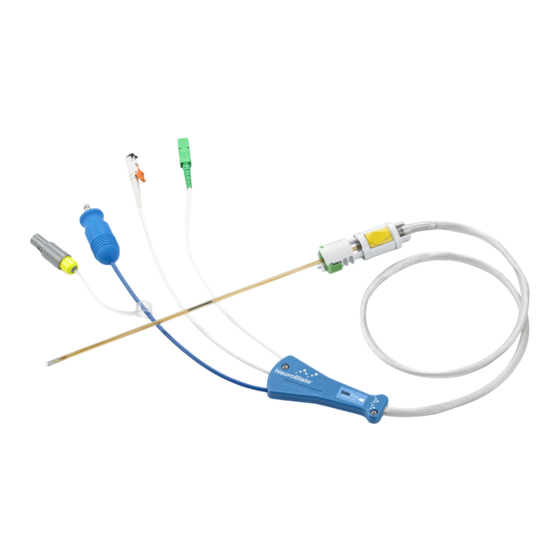
The LDP’s are available in multiple lengths and configurations in two outside diameters: 3.3 and 2.2 mm. The appropriate length is determined during clinical use by the NeuroBlate M*Vision software. The appropriate probe configuration and diameter is determined by the physician depending on the clinical need. - Page 12 NeuroBlate® System Instructions for Use 80469 Rev D – Nov 16, 2018 Probe Ruler/ Protective Cover Figure 1.4: Laser Delivery Probe Body; Inside Ruler/Protective Cover The LDP assembly (see Figures 1.3, 1.4 and 1.5) is comprised of: 1) Removable Ruler/Protective Cover...
-
Page 13: Sidefire® Optic 3.3 Directional Laser Probe
NeuroBlate® System Instructions for Use 80469 Rev D – Nov 16, 2018 1.2.2. SideFire® Optic 3.3 Directional Laser Probe Cooling Tube Fiber Line Tip Probe Lens (laser beam exit) Optical Temperature Sensor Probe Shaft Figure 1.6: Detail of the SideFire® Optic 3.3 Directional Laser Probe Tip (SFP) The SideFire®... -
Page 14: Fullfire® Optic Diffusing Tip Laser Probes
NeuroBlate® System Instructions for Use 80469 Rev D – Nov 16, 2018 1.2.3. FullFire® Optic Diffusing Tip Laser Probes Figure 1.7: Detail of the Distal End of the FullFire® Optic Diffusing Tip Laser Probe The FullFire® Optic 3.3 and smaller diameter FullFire™ Optic 2.2 Diffusing Tip Laser Probes are comprised of the same components and mechanical interfaces as the SideFire®... -
Page 15: Laser Delivery Probe Selection
NeuroBlate® System Instructions for Use 80469 Rev D – Nov 16, 2018 1.2.4. Laser Delivery Probe Selection Selection of the SideFire® Optic Directional Laser Probe (SFP) versus the FullFire® Optic Diffusing Tip Laser Probe should be determined by the size and shape of the intended ablation area. -
Page 16: Advanced Probe Driver (Apd) And Robotic Probe Driver (Rpd)
Both the (single use) Advanced Probe Driver (APD) and (single use) Robotic Probe Driver (RPD) are mounted to the NeuroBlate System Interface Platform (IP). The APD follower is designed to be mounted onto a skull-mounted stereotactic anchoring device. The RPD follower is a lower profile version of the APD follower designed to adapt to an appropriate skull bone anchor. - Page 17 NeuroBlate® System Instructions for Use 80469 Rev D – Nov 16, 2018 Shortened Follower Figure 1.9: Robotic Probe Driver (RPD) with shortened follower stem • The APD and RPD Commander can be used to manipulate the Laser Probe (translation and...
- Page 18 NeuroBlate® System Instructions for Use 80469 Rev D – Nov 16, 2018 • The APD Follower (Figure 1.10) can be mounted to a stereotactic miniframe such as but not limited to the AXiiiS® Stereotactic Miniframe (see Section 8.6.2 Attach Advanced Probe Driver (APD) to Interface Platform and AXiiiS) and provides supportive interface to the Laser Probe during use.
-
Page 19: Operating Modes
PERATING ODES The NeuroBlate System has 2 modes of operation, Active and Standby. These modes are defined by 5 essential functions the system can provide and more specifically, the state of each function. The system is in Active mode if at least one Essential Function is activated (shown “in operation”... -
Page 20: Indications For Use
80469 Rev D – Nov 16, 2018 2. Indications for Use The Monteris Medical NeuroBlate System is indicated for use to ablate, necrotize, or coagulate intracranial soft tissue, including brain structures, through interstitial irradiation or thermal therapy in medicine and surgery in the discipline of neurosurgery with 1064 nm lasers. -
Page 21: Contraindications
NeuroBlate® System Instructions for Use 80469 Rev D – Nov 16, 2018 3. Contraindications The following are contraindications that apply to the NeuroBlate System: • Patients who are contraindicated for MRI, including patients who may have contraindications due to implanted medical devices. -
Page 22: Warnings, Cautions, & Safety Requirements
A causal relationship need not have been proved. Symbols displayed on or in the NeuroBlate System and its documentation are: 4.1. I... -
Page 23: Equipment Labels
NeuroBlate® System Instructions for Use 80469 Rev D – Nov 16, 2018 4.2. E QUIPMENT ABELS Dornier Laser: - 23 -... - Page 24 NeuroBlate® System Instructions for Use 80469 Rev D – Nov 16, 2018 NeuroBlate System: - 24 -...
-
Page 25: General Warnings
ENERAL ARNINGS The following are general warnings that apply to the NeuroBlate System as a whole; please consult the complete NeuroBlate System IFU for device specific instructions for all accessories used (such as the Dornier Laser, Monteris AtamA, Monteris AXiiiS, and system MRI) for warnings specific to those devices. - Page 26 • Laser eye protection provided with the NeuroBlate system must be worn in the MRI Scanner room during operation of the laser. • Using eye protection other than what was specifically provided with the NeuroBlate system may not provide adequate protection for the NeuroBlate laser wavelength.
- Page 27 • If the patient head position changes relative to the head fixation device or the initial MRI position set during the landmark procedure at any point during the NeuroBlate System procedure, new imaging must be acquired and set as the master series or thermal energy may be delivered in an unintended area causing patient injury.
-
Page 28: Electronics Rack Warnings
NeuroBlate® System Instructions for Use 80469 Rev D – Nov 16, 2018 As part of the operation of the NeuroBlate System, the user must beware of the strong magnetic field in the MRI room. Extreme caution must be used before bringing in any equipment into the MR environment. -
Page 29: Advanced Probe Driver, Robotic Probe Driver And Ldp Warnings
NeuroBlate® System Instructions for Use 80469 Rev D – Nov 16, 2018 4.3.2. Advanced Probe Driver, Robotic Probe Driver and LDP Warnings The following are specific warnings that apply to the NeuroBlate Probe Drivers (APD and RPD) and Laser Delivery Probe (LDP). WARNING: •... -
Page 30: General Cautions
• Refer to the MRI manufacturer’s instructions for use to ensure proper use of hearing protection during operation of the MRI scanner. • NeuroBlate System should be connected to a power outlet with >=15 A circuit breakers. This outlet is to be used by the NeuroBlate system only. Failure to comply may result in power failure during the procedure. - Page 31 ±1.5 mm variance between the actual thermal dose and the Blue TDT line depicted. • The temperature value indicated from the NeuroBlate laser probe is not an accurate measurement of core body temperature. Do NOT use this value.
-
Page 32: Laser Delivery Probes, Advanced Probe Driver And Robotic Probe Driver
• The Laser Safety Officer (or employee with appropriate training and authority) must ensure that local safety regulations are observed when the laser is used. • The system must only be installed and serviced by Monteris Medical employees or by persons authorized by Monteris Medical. -
Page 33: Inspection , Cleaning , Disinfection , Sterilization
DO NOT USE if the sterile barrier integrity is compromised or contents appear damaged; contact your Monteris Medical representative for replacement items. • The Laser Delivery Probe, Advanced Probe Driver and Robotic Probe Driver are for single use only. -
Page 34: Mri Conditional Status
• The Laser Delivery Probe should NOT be moved linearly during any MR imaging acquisition • The NeuroBlate System is compatible with the following 1.5 T or 3.0 T MRI systems: o Siemens - minimum software versions VB17, VD13 and VE11 or higher ... - Page 35 NeuroBlate® System Instructions for Use 80469 Rev D – Nov 16, 2018 The following table outlines acceptable operation with respect to NeuroBlate System modes of operation (see section 1.3) and the MRI: No Scanning GRE Sequence for Diagnostic Imaging (Idle Mode)
-
Page 36: Mr Image Artifact
MR artifact from the probe, and the right-most images have a representation of the probe overlaid on the images for reference. In order to successfully complete the “Insert” workflow step in a NeuroBlate procedure (see Section 8.7), the current location of probe is identified from the probe artifact in the MR image. - Page 37 NeuroBlate® System Instructions for Use 80469 Rev D – Nov 16, 2018 3.3 mm 2.2 mm 3.3 mm 2.2 mm 2.2 mm 3.3 mm 2.2 mm 3.3 mm Figure 5.2: Parallel (top row) and perpendicular (bottom row) MPRAGE 3T MR images near...
-
Page 38: Potential Harms Or Hazards
Laser Delivery Probe advancement into, or laser ablation in cerebral vasculature or highly vascularized targets (especially in patients with predisposition to bleeding) may result in hemorrhage. • A malfunction or misuse of the NeuroBlate system may result in an incomplete or aborted procedure. - 38 -... -
Page 39: Neuroblate® System Setup
ETUP MRI Sequence Protocols It is recommended to create a NeuroBlate specific sequence protocol folder or list on the MR user interface software so the operator can easily identify, load, and execute the required MR acquisitions. It may also be beneficial to include routine radiology pulse sequences for easy access during the case. - Page 40 REAL TIME TRANSFER. Imaging Options ASSET, Multi-Phase, Sequential For GE Signa MRI with v12.X or v26.X Software, the configuration variables (CV) parameter values noted below must be entered manually prior to acquiring the NeuroBlate Thermal Sequence: 2D FSPGR Parameter USER_CV name...
- Page 41 NeuroBlate® System Instructions for Use 80469 Rev D – Nov 16, 2018 Philips MRI – FFE Scan type Imaging Scan Mode Technique Contrast enhancement 27msec 19.1msec Flip Angle 30 deg. Summary Panel: Water Fat shift (3T) / BW (Hz) 4.346 pixels / 99.9Hz Water Fat shift (1.5T) / BW (Hz)
- Page 42 NeuroBlate for planning purposes. This one is typically named MONTERIS. • Constraints: o Localizers or Surveys - these are not needed for NeuroBlate setup and should not be transferred. o Dual Echo sequences - these sequences produce two image data sets within the same series folder (T2 and Proton Density weighted) at identical positions and orientations.
-
Page 43: Co 2 Tanks
WARNING: Tank valves must be closed before replacing. Serious operator injury may occur. The NeuroBlate System uses medical grade CO gas coolant for the Laser Probe (Figure 7.2). The Electronics Rack is designed to hold two “E” size tanks. The system user is required to supply the tanks. - Page 44 NeuroBlate® System Instructions for Use 80469 Rev D – Nov 16, 2018 Line Yoke Tank Valve Line Yoke T-Handle Figure 7.2 Tanks Mounted to Electronics Rack - 44 -...
-
Page 45: Mri Shield Penetration For Neuro Blate Cabling
RF shield to prevent conduction of noise into the room. Typically the NeuroBlate cabling is left permanently attached on both sides of the filter panel. • If the installation requires the cables to be disconnected between cases, insert dust covers into the laser fiber and optical temperature sensor connectors when plugs are not inserted (see orange arrows Figure 7.31) and cover the end of the temperature sensor fiber with the... - Page 46 NeuroBlate® System Instructions for Use 80469 Rev D – Nov 16, 2018 Figure 7.32 Waveguide Filter Panel Assembly and Dust Cover Locations In MRI configurations where a Waveguide will be used for connector module attachment access, it may be necessary to attach/remove the panel assembly if the waveguide is used in other applications (Figure 7.32).
-
Page 47: Neuro Blate System Control Workstation
• Turn on the power switch at the side of the monitor (see Figure 7.4) and the monitor will display NeuroBlate System logo launch screen. • Double-click on the M*Vision for NeuroBlate System icon to launch the software application. CAUTION: The user must perform a Shut down under at the Start menu of the Windows operating software before using the power switch to power down the system. -
Page 48: Software Boot Up And Launch Screen
MRI host computer to ensure the timescale of patient data from the MRI is more accurately aligned to events within the NeuroBlate system - Contact Monteris Technical Support if changes to the time setting are required •... -
Page 49: Neuro Blate System M*Vision ™ Software Application
Figure 7.51: M*Vision User Interface – Workflow Task Icons M*Vision Software in the NeuroBlate System works with and augments current neurosurgical practices and workflows, a User mode may be selected to describe high-level objective for neurosurgical use. Once in selected mode, M*Vision provides appropriate tasks, suggests workflows (sequences of actions) and provides appropriate tools to accomplish such actions. -
Page 50: Workflow Task Icons And Description
NeuroBlate® System Instructions for Use 80469 Rev D – Nov 16, 2018 Menu Bar Task Icons MRI Type Robotic/Manual Mode Probe Status Figure 7.5.1: M*Vision Task Icons 7.5.1. Workflow Task Icons and Description Start - Select MRI scanner type and Robotic vs. Manual Mode for LDP manipulations... -
Page 51: Main Menu Bar Options
NeuroBlate® System Instructions for Use 80469 Rev D – Nov 16, 2018 7.5.2. Main Menu Bar Options Table 7.5.2: Main Menu Bar Dropdown Menu Options File Open Profile - Load an existing patient plan from a folder Close Profile - Close and Save an active patient profile Import Profile - Import patient Plan/Profile from a hard drive folder in Windows explorer and move to local Plan directory. -
Page 52: Toolbar And System Status Description
NeuroBlate® System Instructions for Use 80469 Rev D – Nov 16, 2018 7.5.3. Toolbar and System Status Description Figure 7.5.3: Main Toolbar All M*Vision workflow tasks with the exception of Start use a common toolbar (Figure 7.5.3), found at the upper left side of the software GUI. The Toolbar icons apply to functions used for selection, image manipulation or image adjustment within the image view panes using the left mouse button (unless otherwise noted in table 7.2). - Page 53 NeuroBlate® System Instructions for Use 80469 Rev D – Nov 16, 2018 Table 7.5.3: Tools Available on Main Toolbar (context sensitive) Default Arrow Tool - used for default manipulation/selection for the GUI Window Width/Level (image contrast and brightness) - drag horizontally for width,...
-
Page 54: Hardware Interfaces
For some MRI vendors/makes/models, the communication cable may be disconnected between the MRI and the NeuroBlate System. If this is the case, this communication cable needs to be reconnected prior to starting a NeuroBlate procedure and should be disconnected after the NeuroBlate procedure. -
Page 55: Thermal Monitoring Slice Planes
Rendered Figure 7.5.71: Main User Interface Layout The NeuroBlate System M*Vision Software monitors three, 5 mm thick slice planes simultaneously during thermal delivery (see Figure 7.5.71). Each slice plane is separated by a 0.25mm slice gap. There are 13 slice plane locations available for thermal imaging along the set trajectory which are numbered Distal 2 (D2), Distal 1 (D1), 1 through 9, Proximal 1 (P1), Proximal 2 (P2). - Page 56 NeuroBlate® System Instructions for Use 80469 Rev D – Nov 16, 2018 The FullFire LDP requires a slightly different positional setup compared to the SideFire LDP to ensure the central monitoring slice captures the maximum heating. The FullFire has a larger laser emission profile than the SFP along a 6mm length of fiber back from the tip of the fiber.
-
Page 57: Neuroblate® System Procedure Workflow
8.1.1. M*Vision Software Start Screen Figure 8.1.1: Plan Start Screenshot The NeuroBlate System is configured for the host MRI during installation. If the NeuroBlate System is set up for more than one host MRI, the user must define the scanner to be used for the procedure at... -
Page 58: Load And Register Image Data Within Plan Register Task
NeuroBlate® System Instructions for Use 80469 Rev D – Nov 16, 2018 8.1.2. Load and Register Image Data within Plan Register Task Figure 8.1.21: Loading DICOM Data in Register Task The Register task allows image data pushed from the host MRI scanner to be received to M*Vision or a USB drive. - Page 59 NeuroBlate® System Instructions for Use 80469 Rev D – Nov 16, 2018 Figure 8.1.22: Image Co-Registration in Register Task • Click a thumbnail view to the right side of the image view panes for the desired image dataset to be registered (highlighted green in Figure 8.1.22) •...
- Page 60 NeuroBlate® System Instructions for Use 80469 Rev D – Nov 16, 2018 Figure 8.1.23: Using the Blend tool to assess registration accuracy • Use the Blend slider bar in the right menu bar to blend the imported data set into or out of the Master series (Figure 8.1.23)
-
Page 61: Create Region Of Interest (Roi) Volumes Within The Plan Volumes Task
NeuroBlate® System Instructions for Use 80469 Rev D – Nov 16, 2018 8.1.3. Create Region of Interest (ROI) Volumes within the Plan Volumes Task Figure 8.1.31: Create an ROI Volume in Volumes task The Volumes task allows the user to outline up to ten regions of interest (ROI) volume contour annotations within the data set in different (pre- set) colors. - Page 62 NeuroBlate® System Instructions for Use 80469 Rev D – Nov 16, 2018 Push Tool Figure 8.1.32: Edit the Generated Volume Contour Once the volume is generated the created contours can be edited in the acquisition plane (right side view pane only): •...
-
Page 63: Create Intended Trajectories Within The Trajectory Task
NeuroBlate® System Instructions for Use 80469 Rev D – Nov 16, 2018 8.1.4. Create Intended Trajectories within the Trajectory Task Figure 8.1.41: Trajectory Creation in Trajectory The Trajectory task is used for initial trajectory planning. The image view panes are oriented to show three orthogonal planes reconstructed along the current, active trajectory. - Page 64 NeuroBlate® System Instructions for Use 80469 Rev D – Nov 16, 2018 Figure 8.1.42: Initial Trajectory Displayed by M*Vision • Create additional trajectories by adjusting the grab handles to the desired locations, and select New in the right menu Figure 8.1.42 •...
-
Page 65: Saving A Plan
NeuroBlate® System Instructions for Use 80469 Rev D – Nov 16, 2018 8.1.5. Saving a Plan Patent Name One_ID number Patent Name Two_ID number Figure 8.1.5: Plan Saving Hierarchy M*Vision continuously saves all treatment planning profiles. If the system shuts down or is turned off during the planning phases, the plan profile will be saved using the patient name embedded within the DICOM image data loaded into the system during planning. -
Page 66: Opening A Saved Plan
NeuroBlate® System Instructions for Use 80469 Rev D – Nov 16, 2018 8.1.6. Opening a Saved Plan Figure 8.1.61: File Menu To Open a Plan If a plan has been created and saved prior to treatment, this data can be loaded into M*Vision software using the following steps: •... -
Page 67: Operating Room : Pre -Procedure Preparation
Refer to Instructions for Use for the head coil and fixation system used. WARNING: The patient head must be secured with a Head Fixation Device and remain fixed within magnet space for entire imaging portion of the outlined NeuroBlate System workflow. -
Page 68: Prepping And Sterile Draping For Trajectory Guidance Devices
• Trefenate the skull along the desired trajectory using a 4.5 mm twist drill bit 8.2.7.2. Skull Bone Anchor Skull bone anchors appropriate for delivery of the NeuroBlate laser delivery probes must be manufactured from materials that are MRI conditional at 1.5 T and/or 3.0 T. The internal diameter of the anchor must accommodate either of the two available 2.2 mm or 3.3 mm laser... -
Page 69: Create A Pathway To The Intended Target
NeuroBlate® System Instructions for Use 80469 Rev D – Nov 16, 2018 8.2.8. Create a Pathway to the Intended Target • Use standard surgical technique to open the Dura mater to ensure clear passage for the LDP into the brain. -
Page 70: Laser Delivery Probe (Ldp) Depth Stop And Size Determination
NeuroBlate® System Instructions for Use 80469 Rev D – Nov 16, 2018 8.2.9. Laser Delivery Probe (LDP) Depth Stop and Size Determination 8.2.9.1. AXiiiS Stereotactic Miniframe - Depth Stop and Size Follow the AXiiiS Stereotactic Mini-Frame Instructions for Use for device alignment instructions. -
Page 71: Skull Bone Anchor Such As Monteris Mini-Bolt - Depth Stop And Size
NeuroBlate® System Instructions for Use 80469 Rev D – Nov 16, 2018 8.2.9.2. Skull Bone Anchor such as Monteris Mini-Bolt - Depth Stop and Size The LDP size and depth stop setting will require confirmation during the OR preparation stage if a skull bone anchor instead of AXiiiS is to be used for the procedure. - Page 72 NeuroBlate® System Instructions for Use 80469 Rev D – Nov 16, 2018 The depth stop setting (or LDP ruler setting) on the LDP is derived from its use with the AXiiiS device where the depth of the LDP is measured from the top most point of the beam direction fiducial marker (BDM) within the AXiiiS central ball joint.
- Page 73 NeuroBlate® System Instructions for Use 80469 Rev D – Nov 16, 2018 OR Preparation Step illustration with RPD and a standard bone anchor PDP x L (mm) Probe Depth Stop Setting = L - 27mm Figure 8.19c: Example of RPD Depth Stop Calculation with a Skull Bone Anchor The following table helps identify the target depth range for the probe sizes available when used with a skull bone anchor with/without Robotic Probe Driver.
-
Page 74: Rep For Ransfer To Mri
REP FOR RANSFER TO For NeuroBlate procedures performed in a Diagnostic MRI the sterile field created around the LDP delivery platform must be maintained throughout the entire procedure. Drape the patient head for transfer to the MRI according to hospital procedure. A sterile bag may be placed around the patient head and sterile field. - Page 75 80469 Rev D – Nov 16, 2018 Use of Siemens Aera and Skyra MRI Prior to use of the AtamA Stabilization System and NeuroBlate Interface Platform, a fluid barrier must be placed over the coil connections and connectors on the MR couch. Plastic drapes should be placed over the coil connections (when not plugged in) and over the coil connectors when plugged in.
- Page 76 NeuroBlate® System Instructions for Use 80469 Rev D – Nov 16, 2018 Attachment Method 1– AtamA Attachment Interface 1. Ensure AtamA patient board is fully installed and secure on the MRI table. 2. Slide the arm ends (furthest away from the interface platform) into the IP Arm interface completely until the “stop rings”...
- Page 77 NeuroBlate® System Instructions for Use 80469 Rev D – Nov 16, 2018 Attachment Method 2 – IMRIS Table Receptacle 1. Remove the IMRIS OR table headrest if not needed for procedure. If needed for procedure, attachment method 3 should be used in conjunction with a different arm set.
- Page 78 If IMRIS clamp is in the way, slide further down rail as to not interfere with the NeuroBlate attachment or procedure. 2. Insert arms through side holes and tighten clamp knob onto the arm shaft. Note: Do not over tighten the screw as this may damage the plastic.
- Page 79 NeuroBlate® System Instructions for Use 80469 Rev D – Nov 16, 2018 Connecting Blocks (2) Pivot Pin (2) Table Slots Thumbscrews (4 each side) Table Anchor Connecting Blocks (2) Pivot Pin (2) Thumbscrews (2 each side) Table Table Slots Anchor Figure 8.44 i, j :...
- Page 80 NeuroBlate® System Instructions for Use 80469 Rev D – Nov 16, 2018 Attachment Method 5 – Philips Ingenia MR table 1. The Philips “DStream” coil connection interface must be inserted into the head end of the MR and connected in order to use the Philips SENSE Flex coils (See Figure 8.45) 2.
- Page 81 NeuroBlate® System Instructions for Use 80469 Rev D – Nov 16, 2018 Interface Platform to Arm Connection Connect/Disconnect The interface platform can be attached and detached quickly from the arms by attaching and removing the brass thumbscrews shown in Figure 8.46.
- Page 82 NeuroBlate® System Instructions for Use 80469 Rev D – Nov 16, 2018 PCM Mounting DO NOT place beyond the inner surface of the Knob Adapter at IP Cross Arm Legacy IP Position PCM Bracket Mounting Knob Figure 8.48: PCM Mounting Position Limits (green arrows denote acceptable mounting position range;...
- Page 83 NeuroBlate® System Instructions for Use 80469 Rev D – Nov 16, 2018 PCM Mounting Hub Locking Thumbscrew Mounting PCM Hub Locking Thumbscrew Figure 8.49: PCM Mounting Hub (left); PCM mounted to IP Arms at 45° (top right); PCM to IP at 0° (bottom right) •...
- Page 84 NeuroBlate® System Instructions for Use 80469 Rev D – Nov 16, 2018 CAUTION: Ensure that excessive strain is not placed on the LDP or Probe Connectors. • Wrap the redundant PCM strap around the IP arms if using the bracket and secure.
-
Page 85: Trajectory Confirmation And Beam Fiducial Marker Detection
NeuroBlate® System Instructions for Use 80469 Rev D – Nov 16, 2018 8.5. T RAJECTORY ONFIRMATION AND IDUCIAL ARKER ETECTION Trajectory confirmation and Beam Fiducial Marker Detection workflow is defined by the type of trajectory guide being used for the procedure: The established trajectory of the AXiiiS Stereotactic Miniframe should be evaluated using MRI prior to inserting the Laser Probe into the brain. -
Page 86: Scan And Register Data In M*Vision Using Plan Register Task
• Push the acquired image data to the Monteris Control Workstation via the DICOM node set up on the MRI system. Once data is pushed from the MRI to NeuroBlate workstation, the data automatically loads into the M*Vision software when in the Plan Register or Treat Register workflow task. -
Page 87: Create Trajectories Within Trajectories Task For Axiiis
NeuroBlate® System Instructions for Use 80469 Rev D – Nov 16, 2018 8.5.3. Create Trajectories within Trajectories Task for AXiiiS • Using the M*Vision Plan Trajectories workflow step, establish/adjust the software rendered Laser Probe trajectory(s) along the imaged position of the MRI Trajectory Wand following steps described in section 8.1.4 Create Intended Trajectory... -
Page 88: Identify Ball Marker Selection Within The Align Task
NeuroBlate® System Instructions for Use 80469 Rev D – Nov 16, 2018 8.5.5. Identify Ball Marker Selection within the Align Task Once the trajectory has been adjusted and saved within the Trajectory step, the beam direction marker (BDM) within the AXiiiS or attached to the RPD device needs to be defined to establish the depth setting (AXiiiS only) and laser firing direction (AXiiiS and RPD) within M*Vision software. - Page 89 NeuroBlate® System Instructions for Use 80469 Rev D – Nov 16, 2018 Identify BDM using ClearPoint Fiducial Marker Attached to the Robotic Probe Driver (RPD) If the RPD device has not been attached yet, select an arbitrary Ball Marker position outside of the skull within 3-5cm of the estimated skull entry point near the trajectory.
-
Page 90: Self-Test, Probe Driver Attachment And Ldp Insertion
NeuroBlate® System Instructions for Use 80469 Rev D – Nov 16, 2018 8.6. Self-Test, Probe Driver Attachment and LDP Insertion 8.6.1. Final Trajectory Adjustment in Insert 8.6.1.1. AXiiiS Workflow The selected trajectory should align to the MR visible wand if the AXiiiS is properly aligned to the intended trajectory (Figure 8.6.11). - Page 91 WARNING: Creating a greater than 7.5mm radial ablation area may exceed the NeuroBlate System’s ability to monitor thermal dose in the longitudinal direction.
-
Page 92: Non-Axiiis Workflow
NeuroBlate® System Instructions for Use 80469 Rev D – Nov 16, 2018 8.6.1.2. Non-AXiiiS Workflow The trajectory creation step in sec 8.5.4 should capture the final trajectory adjustment in this case since it was aligned to the probe signal void. No further adjustment should be needed but ensure that the software rendered LDP aligns to the LDP signal void when applicable. -
Page 93: Probe Driver (Apd And Rpd) Attachment And Connections (If Applicable)
NeuroBlate® System Instructions for Use 80469 Rev D – Nov 16, 2018 8.6.2. Probe Driver (APD and RPD) Attachment and Connections (if Applicable) • Upon entering the MRI scan room, press the Next button on the Interface Platform (IP) to... - Page 94 NeuroBlate® System Instructions for Use 80469 Rev D – Nov 16, 2018 Commander Position Feedback Plug Next Button Figure 8.6.21: Interface Platform: Commander, Position Feed Back and Line Attachments • Connect the Position Feedback Plug (cable) as shown in Figure 8.6.21 •...
- Page 95 NeuroBlate® System Instructions for Use 80469 Rev D – Nov 16, 2018 Dashed line indicates alignment of Directional Interface Tab 1 to Directional Directional Interface Notch 1. Interface Notch 2 Directional Interface Locking Thumbscrew Directional Interface Tab 2 Figure 8.6.22: Attaching the Follower to AXiiiS...
- Page 96 NeuroBlate® System Instructions for Use 80469 Rev D – Nov 16, 2018 Workflow using a Skull Bone Anchor and RPD If the hospital has access to a sterile MRI visible fiducial marker (such as the ClearPoint Fiducial Marker), the fiducial marker may be placed on the underside of the L-shaped Guide Rail on the Probe Driver Follower as shown in Figure 8.6.23:...
- Page 97 NeuroBlate® System Instructions for Use 80469 Rev D – Nov 16, 2018 Figure 8.6.24: Attaching the Legacy RPD to the Mini-Bolt Figure 8.6.25: Attaching the Current RPD to the Mini-Bolt - 97 -...
- Page 98 NeuroBlate® System Instructions for Use 80469 Rev D – Nov 16, 2018 Self-Test Steps (only if APD/ RPD selected for use) Interface Platform Display • Connect the Position Feedback Plug (cable) as shown in Figure 8.33. • Press the Next button when task is complete.
-
Page 99: Laser Delivery Probe (Ldp) Size Selection And Insertion
80469 Rev D – Nov 16, 2018 8.6.3. Laser Delivery Probe (LDP) Size Selection and Insertion The NeuroBlate LDPs are provided in multiple lengths for lesions of varying depths. Refer back to section 8.2.9. Laser Delivery Probe (LDP) Depth Stop and Size Determination. - Page 100 NeuroBlate® System Instructions for Use 80469 Rev D – Nov 16, 2018 Figure 8.6.31 a - f: Remove the LDP from the tray. • Remove the LDP main section by gently pulling up on the probe interface (Figure 8.6.31 a) •...
- Page 101 NeuroBlate® System Instructions for Use 80469 Rev D – Nov 16, 2018 CAUTION: Never pull on the thinner tubular or cable sections of the laser, cooling, temperature sensor, and probe detection lines, as this may damage the components. CAUTION: The Laser Delivery Probe is fragile. Handle with care.
- Page 102 NeuroBlate® System Instructions for Use 80469 Rev D – Nov 16, 2018 WARNING: An improperly set depth stop may allow the LDP tip to be delivered beyond the intended target which may lead to patient injury. • Carefully remove the Ruler by depressing the (green) release button...
- Page 103 NeuroBlate® System Instructions for Use 80469 Rev D – Nov 16, 2018 The sterile person transfers the LDP connector plugs out of sterile field to a non-sterile person who inserts plugs into their receptacles on the PCM (see Figure 8.6.33).
- Page 104 NeuroBlate® System Instructions for Use 80469 Rev D – Nov 16, 2018 Incomplete Connection Red Glow Figure 8.6.35: Laser Fiber Plug Not Fully Seated - red glow in mating connector and gap between components (left); Laser Fiber Plug Fully Seated - no red glow in...
- Page 105 NeuroBlate® System Instructions for Use 80469 Rev D – Nov 16, 2018 WARNING: The LDP fiber connector must be completely engaged into the corresponding Interface Platform receptacle. Failure to do so may cause receptacle heating and reduce the energy delivered. This may result in equipment damage or injury to patient.
- Page 106 NeuroBlate® System Instructions for Use 80469 Rev D – Nov 16, 2018 Self-Test Step Interface Platform Display • Perform the Laser aiming beam test. • The visible pilot laser provides a bright, red laser light exiting the LDP tip in the correct orientation from the LDP must be visible.
- Page 107 NeuroBlate® System Instructions for Use 80469 Rev D – Nov 16, 2018 WARNING: A non-existent or weak visible laser beam may be an indication of an improperly connected laser fiber. If this condition occurs, DO NOT CONTINUE as it may result in equipment damage or injury to patient.
- Page 108 NeuroBlate® System Instructions for Use 80469 Rev D – Nov 16, 2018 Using the following steps, the sterile LDP can now be advanced into the APD/RPD Follower and into the brain until the LDP Locking Interface comes in full contact with the Mating Adapter on the Follower (see Figure 8.6.31).
- Page 109 NeuroBlate® System Instructions for Use 80469 Rev D – Nov 16, 2018 • Ensure that the LDP is fully engaged to the Probe Driver Follower prior to manipulating LDP in tissue • Confirm by gently pulling back on the LDP to ensure it is properly locked in place •...
-
Page 110: Mri Confirmation Of Ldp Insertion
NeuroBlate® System Instructions for Use 80469 Rev D – Nov 16, 2018 8.7. MRI C LDP I ONFIRMATION OF NSERTION Once Self-Test is complete and the LDP has been inserted, the software rendered LDP must be adjusted to match to the actual LDP position as placed in brain. At this point a new MRI scan must be acquired and sent to the M*Vision software. - Page 111 NeuroBlate® System Instructions for Use 80469 Rev D – Nov 16, 2018 Philips MRI Philips MRI Entry Note: For Philips position and orientation entry, the base plane is also needed for entry on Philips MRI. This is given by the slice orientation label (e.g.
- Page 112 NeuroBlate® System Instructions for Use 80469 Rev D – Nov 16, 2018 Figure 8.7.1: Trajectory Confirmation If Manual Probe Movement was selected at the M*Vision Start task (manual mode), an additional Probe Confirmation header will be visible in the right side menu. After either skipping or completion of...
-
Page 113: Elivery And
Tissue thermal interactions (such as coagulation) are not governed by the temperature of the tissue alone. The duration for which the tissue is exposed to any given temperature is also of critical consequence. The NeuroBlate System uses non-invasive, near real time MRI thermometry to monitor temperature change and duration. -
Page 114: Enable The Mri For Real Time Transfer
Note: The MRI system will revert to the default configuration at the end of the NeuroBlate procedure. CAUTION: Do not enable the real time data transfer interface prior to this point in the workflow. - Page 115 CAUTION: For Siemens MRI software version 19, the values for the Switches Menu should be reset to their original values at the end of the NeuroBlate procedure following the same procedure outlined on pages 105 – 106 to prevent suspending the MRI software requiring an MRI system reboot to clear.
- Page 116 NeuroBlate® System Instructions for Use 80469 Rev D – Nov 16, 2018 Special Instruction for GE MRI running software v15.x or higher only: • Check if SVAT hosts is activated 1. Open a Command Window (TOOLS Icon Dropdown Menu-> Command Window) 2.
- Page 117 NeuroBlate® System Instructions for Use 80469 Rev D – Nov 16, 2018 • Check if LAIS server is already enabled 1. Open a Command Window (TOOLS Icon Dropdown Menu-> Command Window) 2. Type ‘cd /w/init’ then press Enter 3. Type ‘ls lais.init*’ then press Enter 4.
- Page 118 NeuroBlate® System Instructions for Use 80469 Rev D – Nov 16, 2018 • If LAIS is not properly running (0 or 1 active process), manually restart LAIS: 1. Open a Command Window (TOOLS Icon Dropdown Menu-> Command Window) 2. Type ‘killall lais’ then press Enter 3.
- Page 119 NeuroBlate® System Instructions for Use 80469 Rev D – Nov 16, 2018 Special Instruction for GE Signa MRI running software v12.x : • Ensure the Samba service is running: 1. Open a Command Window (Right click on main screen to display Root Menu. Select Service Tools ->...
- Page 120 Hospital network and directly connected to the NeuroBlate Main PC forming a direct peer-to- peer network connection. In this case, both the NeuroBlate system and the Philips MRI will be disconnected from the hospital PACS network during treatment monitoring. The MRI connection to the PACS network can be restored following treatment monitoring once real time data transfer is no longer necessary.
-
Page 121: Position Thermal Monitoring Planes In M*Vision
NeuroBlate® System Instructions for Use 80469 Rev D – Nov 16, 2018 8.8.1. Position Thermal Monitoring Planes in M Vision Figure 8.8.1: Adjustment of LDP Linear Position • Use the white cursor arrow to adjust the software rendered LDP depth by clicking on and dragging light blue capsule at the distal end of the software rendered probe to the desired linear position for thermal delivery (Figure 8.8.1) - Page 122 WARNING: If the patient head position changes relative to the head fixation device or the initial MRI position set during the landmark procedure at any point during the NeuroBlate procedure, the entire head must be re-scanned to include the AXiiiS (if applicable) using a 3D volumetric scan.
- Page 123 WARNING: The thermal monitoring planes must be centered at the middle of the FullFire laser emission area to adequately capture thermal dose. WARNING: Creating a greater than 7.5mm radial ablation may exceed the NeuroBlate System’s ability to monitor thermal dose in the longitudinal direction.
-
Page 124: Thermal Sequence Prescription On The Mri
80469 Rev D – Nov 16, 2018 8.8.2. Thermal Sequence Prescription on the MRI CAUTION: MR Thermometry Data. The MR data must use the NeuroBlate System defined sequence parameters for temperature measurement. This includes use of a specific GRE sequence preinstalled on the target MRI system. The only modifications allowed are position, orientation and phase encode direction depending on the location. -
Page 125: Ge Thermal Sequence Prescription Procedure
NeuroBlate® System Instructions for Use 80469 Rev D – Nov 16, 2018 8.8.2.1. GE Thermal Sequence Prescription Procedure • While in the Treat task within M*Vision, select the Scan Plane icon from the task menu on the right. 1. Acquire Start Point Localizer (3-4 sec scan), using values from Treat All Planes o Perform an Erase All to allow for you to do a keyboard prescription o Make sure that you have only a single image in each orientation (Spacing: 0.0) - Page 126 NeuroBlate® System Instructions for Use 80469 Rev D – Nov 16, 2018 Portion of Scan Plane Parameter Dialog showing information for start and end localizer center position 3. Prescribe Parallel FSPGR single image scan: o Copy/Paste/DoubleClick Parallel FSPGR • Make it active to begin prescription •...
- Page 127 NeuroBlate® System Instructions for Use 80469 Rev D – Nov 16, 2018 • If the cursor values do not match it is possible that a GE MRI Console problem is in effect; to work around the problem you must load a different series into the view;...
- Page 128 4. Acquire Parallel FSPGR Scan (1 sec) 5. Prescribe NeuroBlate Thermal Sequence (or a “template” version of it having a single slice and single phase to start) o Load the parallel (or stack) scan into all views. Use the “OK All” button when...
- Page 129 NeuroBlate® System Instructions for Use 80469 Rev D – Nov 16, 2018 o Similar to Step 3, Left mouse click in top right view near to the cursor; but not on it as you may accidentally move the cursor (similar to previous step).
- Page 130 7. Copy and paste the previously acquired thermal sequence into the MRI sequence queue OR if step 6 used a Template thermal seq (GRE) scan, load the NeuroBlate thermal seq (GRE) scan and Copy the parameters from the Template scan using the “Copy Rx”...
- Page 131 WARNING: To prevent inadvertent corruption of the NeuroBlate Thermal Sequence, change only CV values listed above taking care to not change any others. 15. For v20 and up select the dropdown arrow within the Scan icon on the GE user interface and select Auto Pre-Scan.
-
Page 132: Philips Mri Thermal Sequence Prescription Procedure
Step 1 “Header Scan”: To begin any new thermal acquisition, step 1 requires first loading and preparing the NeuroBlate Thermal Monitoring Sequence from the MRI system’s sequence protocol list. It will be labeled NeuroBlate Thermal Seq (GRE). o Ensure the thermal sequence is properly configured to accomplish Step 1: Dyn scans = 1 (Set in the Dyn/Ang tab) •... - Page 133 80469 Rev D – Nov 16, 2018 o Enter the displayed scan plane parameters from M*Vision (see Fig 8.8.14) into the NeuroBlate Thermal Monitoring Sequences protocol’s geometry parameters in the MRI. This will be in the Offc/Ang tab of the sequence exam card as shown below.
- Page 134 NeuroBlate® System Instructions for Use 80469 Rev D – Nov 16, 2018 Shim Box notification: Center Green Shim box over center of three thermal images Incorrect Placement of Shim Box Correct Placement of Shim Box Step 2: Copy the same scan from step 1 to ensure all parameters are the same except for DynScans.
-
Page 135: Initiate Thermal Monitoring In M*Vision
NeuroBlate® System Instructions for Use 80469 Rev D – Nov 16, 2018 8.8.3. Initiate Thermal Monitoring in M*Vision • Select the Start Acquisition button under Monitoring Status on the M*Vision the right menu bar This triggers acceptance of this header scan by a DICOM push from the Philips MRI 8.8.3.1. - Page 136 NeuroBlate® System Instructions for Use 80469 Rev D – Nov 16, 2018 • Alternatively, click on Patient ->Administration, and then on the Queue Manager button shown by the red arrow below (similar feature on R3, R4, R5 software) A finished transfer would be listed as Finished, and a pending one would be listed as Executing in the status column.
-
Page 137: Initiate Thermal Monitoring For All Other Mri Types
WARNING: Treatment slice orientation and position must match the treatment planes shown in the views. The MR pulse sequence parameters other than orientation and position must not be changed and must adhere to the requirements for NeuroBlate treatment. WARNING: Do NOT power ON the Interface Platform during MR imaging. Image quality may be compromised. - Page 138 NeuroBlate® System Instructions for Use 80469 Rev D – Nov 16, 2018 36.5° Figure 8.8.3.21: Noise Mask and Reference Point Selection Once MR images begin arriving from the MRI (approximately every 8 seconds), the initialization phase will compute a noise mask and allow for reference point selection. The software receives data and updates the view with an orange-colored overlay indicating mask component pixels as shown in Figure 8.8.3.21.
- Page 139 NeuroBlate® System Instructions for Use 80469 Rev D – Nov 16, 2018 Note: Selecting the Reset Mask button will clear any masked regions and begin the noise and temperature masking stage upon the next measurement. It’s similar to beginning at measurement 1 in a new acquisition but does not require a reset of the current MR acquisition.
- Page 140 WARNING: The temperature value indicated from the NeuroBlate laser probe is not an accurate measurement of core body temperature. Do NOT use this value. Contact Monteris Medical for identification of methods for core body temperature monitoring.
- Page 141 NeuroBlate® System Instructions for Use 80469 Rev D – Nov 16, 2018 2.0° Figure 8.8.3.22: Thermal Dosage Monitoring Display before Lasing The color overlay changes to green which represents the typical baseline body temperature (37 C) which corresponds to the colored temperature scale at the top of screen (Figure 8.8.3.22).
-
Page 142: Initiate Delivery Of Laser Energy To Tissue
LDP connections are made. CAUTION: Ensure the desired LDP trajectory does not interfere with the MR bore or NeuroBlate equipment prior to the insertion of LDP into tissue. CAUTION: Immediately release the laser footswitch upon the display of any error condition. - Page 143 NeuroBlate® System Instructions for Use 80469 Rev D – Nov 16, 2018 CAUTION: During treatment: If there is concern for cranial bleeding, the user may consider acquiring blood-sensitive (GRE) MRI imaging in between laser shots at intervals throughout the procedure. This type of scan should be executed on the MRI only when linear or rotary probe motion is NOT active.
- Page 144 NeuroBlate® System Instructions for Use 80469 Rev D – Nov 16, 2018 Pixels in the temperature map overlay where there is unstable MR phase data will not be displayed (will be dropped from view). If a pixel is noisy or potentially inaccurate, temperature data will not be collected from that pixel.
- Page 145 NeuroBlate® System Instructions for Use 80469 Rev D – Nov 16, 2018 Figure 8.8.3.32: Appropriate distance between yellow TDT line and eloquent tissue - 145 -...
- Page 146 NeuroBlate® System Instructions for Use 80469 Rev D – Nov 16, 2018 Figure 8.8.3.33: Variance of blue TDT line CAUTION: If unexpected or unusual TDT line expansion is encountered (e.g. rapid and erratic or slower than expected), it is recommended that the user should stop thermal delivery and perform diagnostic MR imaging to evaluate the area in and around the target ablation zone.
- Page 147 • Stop thermal delivery by releasing the laser foot pedal • Allow MRI to continue acquiring the NeuroBlate Thermal Monitoring Sequence to allow all heated tissue to return to baseline temperature. For tissue adjacent to the probe, this may require up to 120 seconds. Tissue further away from the probe may take longer to return to baseline temperature.
- Page 148 NeuroBlate® System Instructions for Use 80469 Rev D – Nov 16, 2018 WARNING: Failure to allow all heated tissue to return to baseline temperature prior to stopping MR acquisition may result in inaccurate calculation of thermal dose levels which may lead to patient injury. Maintain MRI acquisition (which ensures internal probe cooling) to allow tissue next to the probe to cool to the baseline temperature which may require up to 120 seconds.
- Page 149 NeuroBlate® System Instructions for Use 80469 Rev D – Nov 16, 2018 Throughout the procedure, use the pixel temperature query tool under the Temperature Point heading in the right menu to monitor brain temperature in the area of thermal monitoring (see Figure 8.8.3.34)
-
Page 150: Electrical Rack Requirements And Technical Data
NeuroBlate® System Instructions for Use 80469 Rev D – Nov 16, 2018 Once all desired treatment slices and angular positions of the probe have been used to optimize the desired coagulation result, the user can select end treatment at any time. Any running MRI acquisition should be stopped after all tissue returns to baseline temperature. - Page 151 NeuroBlate® System Instructions for Use 80469 Rev D – Nov 16, 2018 Table 9.2: Control Workstation Data Electrical Connection Data Class Class I Equipment International Protection rating IPX0 Power Source Electronics Rack Table 9.3: IEC 60601-1:2007 Tables - 151 -...
- Page 152 NeuroBlate® System Instructions for Use 80469 Rev D – Nov 16, 2018 - 152 -...
- Page 153 NeuroBlate® System Instructions for Use 80469 Rev D – Nov 16, 2018 - 153 -...
- Page 154 NeuroBlate® System Instructions for Use 80469 Rev D – Nov 16, 2018 - 154 -...
-
Page 155: Technical Support
80469 Rev D – Nov 16, 2018 10. Technical Support Contact Monteris Medical Customer Support to request service or to report an adverse event: • Monteris Medical Toll Free Customer Support: 1-866-799-7655 Callers may choose to be connected directly to a Technical Services Representative, to leave a message requesting service or product sales, or be connected to the Monteris Medical operator for further assistance. -
Page 156: Contact Information
NeuroBlate® System Instructions for Use 80469 Rev D – Nov 16, 2018 11. Contact Information 11.1. D ISTRIBUTOR ONTACT Monteris Medical Corporation 14755 27th Avenue North Suite C Plymouth, MN 55447 (763) 253-4710 / (866) 799-7655 reporting@monteris.com 11.2. M ANUFACTURED... -
Page 157: Tips And Troubleshooting
Contact your local Monteris Medical Representative for system troubleshooting information or contact: Monteris Medical Customer Support: 1-866-799-7655 Callers may be connected to a Technical Services Representative, to leave a message requesting service or product sales, or be connected to the Monteris Medical operator for further assistance. Table12.1: Software Tips Workflow... - Page 158 NeuroBlate® System Instructions for Use 80469 Rev D – Nov 16, 2018 Table 12.2: Troubleshooting Problem Check / Action Recourse The Commander does not lock Ensure that the mounting holes on the If the problem persists, replace in place bottom of the Commander are...
Need help?
Do you have a question about the Neuroblate and is the answer not in the manual?
Questions and answers